Design and principle of operation of the ignition module
Some old-school motorists call the modules double-spark coils, which makes sense. After all, the coil is the predecessor of the ignition module in the technical evolutionary chain. The module is a paired design consisting of two pairs of windings (primary and secondary) and a switch that alternately switches low-voltage current from one coil to another. In some models of double-spark coils, the commutator is structurally located outside the block.
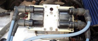
The operation of the module is controlled from an electronic unit that collects and analyzes information from various working components of the engine. The block, unlike the classic coil, has 4 sockets for connecting high voltage wires going to the spark plugs. The pulse occurs in pairs, first at terminals 1 and 4, then 2 and 3.
That is, each of the built-in coils is responsible for the operation of two cylinders. A spark occurs simultaneously, as a pair.
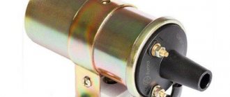
This is what one of the ignition module models looks like. The connector for connecting incoming wires is visible at the top.
At the input, the ignition module has a connector with four terminals. Usually most models have markings opposite them. Pulses from the Hall sensor alternately arrive at contacts A and B, serving as a signal to switch the commutator from one primary winding to another. C and D – ground and power supply (12 V), respectively.
Do-it-yourself installation of the VAZ 2112 ignition module
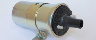
- Having picked up the new coil, first install it in its place by tightening the two nuts that secure it.
- Then place two wires on the sides of the coil and secure them with retaining nuts.
- When installing two side wires, pay attention to the markings that are marked on the sides of the ignition coil (see photo below). So this marking indicates which terminal of the coil should be connected to this or that wire. The blue wire must be connected to the “B” marking, and the red wire must be connected to the “K” marking!
- Then place the high-voltage wire on the central part of the ignition coil.
- And then install the negative terminal on the battery.
On old ignition coils, as a rule, instead of the letters “B” and “K”, the designations “-” and “+” are used, which means the same thing, but only in signs. The blue wire must be connected to the “-” sign, and the red wire must be connected to the “+” sign!
Possible causes of failure
The weak point of the ignition coils and modules is the secondary winding, which generates a high voltage pulse. A coil break or breakdown may occur in it. The following factors lead to this phenomenon:
- use of low-quality or unsuitable candles;
- operation with non-functioning high voltage wires;
- frequent attempts to check the spark.
The high-voltage pulse arising in the secondary winding must be realized (spent). If this does not happen (if the integrity of a high voltage wire is broken, for example), a high-energy electrical pulse seeks an outlet. He will find it, with a high degree of probability, in the thin secondary winding.
Often, a module malfunction occurs when the integrity of poor-quality factory soldering of wires going to the switch elements is violated. This happens from vibration. Also, the cause of non-working coils can be a banal contact failure in the incoming connector. Another factor leading to a malfunction of the ignition unit is often moisture that gets on the device during washing or driving in unusual conditions.
Connecting and replacing VAZ short circuit
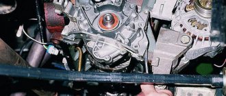
The procedure for removing and installing the ignition coil on old VAZ models:
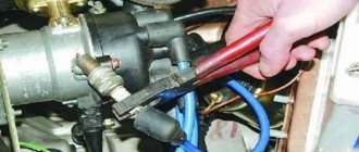
- First, disconnect the central high-voltage wire leading to the distributor (ignition distributor).
- Disconnect all power wires from the coil contacts. Since they are fastened with nuts, you will need an 8 wrench for this.
- If you don’t know which wires to connect to which connector later, it’s better to immediately remember or mark them somehow, so that later during installation you can connect them correctly.
- Unscrew the coil housing. It is attached to a clamp (clamp), which is pressed to the car body with two nuts.
- After the work has been done, you can remove the ignition coil and replace it if necessary.
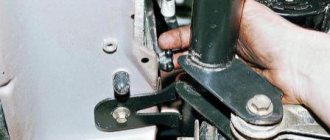
For new type VAZ cars:
- We remove the “minus terminal” from the battery.
- Remove the top protective cover of the engine. If the engine volume is 1.5 liters, then this part is missing and this step is skipped.
- We remove the high-voltage wires from the coil.
- Now, using a 13mm wrench, unscrew the two fasteners.
- Using a 17mm wrench, loosen one bolt securing the coil.
- We take out the module.
- Use a hexagon to unscrew the coil from the holder.
- Assembly is carried out in reverse order.
Particular attention should be paid to the connection, since high-voltage wires must be located in the strict order provided for by the design. If this is not done, the car will stall or the engine may not start at all.
Replacing the ignition coil on a VAZ is quite simple. Even a novice motorist can do this in his garage, and if everything seems too complicated, contact a car service center. Particular attention should be paid to the choice of product, since this will determine how well the engine and ignition system will work.
Symptoms of a problem
It is extremely rare for two built-in coils to fail at once, so it is more likely to be possible to start the engine with a faulty unit. However, even an inexperienced driver will immediately suspect something is wrong. The malfunction will appear as follows:
- unstable (floating) idle speed;
- the engine has difficulty picking up speed;
- characteristic sound of the engine (triple);
- jerking when accelerating (while moving).
Operating a car with such a breakdown is possible (you can drive to a garage or car service station), but it is not advisable unless absolutely necessary.
Similar signs of unstable engine operation are possible with a number of other ignition or fuel supply faults. To differentiate possible breakdowns, the performance of the ignition unit should be determined. It would be useful to check the contacts of the wires coming to the device, as well as their integrity.
Checking module power
Before testing the performance of the coils, you should make sure that a possible breakdown is not caused by a loss of power to the device. First, you need to try to simply restore contact by moving it several times or disconnecting/connecting the block of wires included in the connector. If such manipulation does not lead to improved engine performance, a tester (multimeter) is used to determine the quality of incoming pulses.
The block of wires is removed from the connector. On the block, each terminal (A, B, C, D) has a corresponding socket. Testing with the engine running is done as follows.
- The first contact of the tester is in socket D, the second is to ground. The multimeter switch position is 20 volts. If there is power, the tester shows 12 volts.
- The first contact is in socket C, the second is ground. Switch on ohmmeter (20 Ohm). Normally it shows less than 1 ohm, that is, the mass is normal.
- The first contact is in socket B, the second is ground. 20 volt switch. The norm is not less than 0.3 volts. If this is so, it means that a normal pulse is coming from the Hall sensor to position B.
- Contact A is checked similarly to the previous one.
If such a check shows the norm, you need to test the module. If not, look for the cause in the electrical circuit to the coil.
How to check spark on ignition coil
To see if the coil is working at all, pull the wire from the breaker distributor that comes from the coil. The same test is carried out with it as with the spark plug wires, namely, they bring the wire to a distance of 0.5 cm and turn the starter. Now, regardless of the result, we can accurately talk about the cause of the breakdown.
Checking the ignition coil
In the first case, you need to check the contacts in the distributor-breaker for oxidation, insulation damage, and also check the serviceability of the rotor. If there is no spark due to it, the rotor must be replaced.
Checking the ignition coil also involves inspecting the integrity of the windings for physical damage, as well as burnt spots, which indicate a short circuit in the coil. In these cases, the coil either needs to be repaired or replaced.
If, after checking, you realize that there is a spark in the car, but it does not start, then the ignition switch may need to be replaced.
Methods for diagnosing device performance
The simplest method that will help determine the performance of the coil is to replace it with a similar working device. This is possible if there is somewhere to get it. Please note that the module must match the parameters of the device under test. If the engine with a working coil works as before the breakdown, the ignition module is definitely faulty.
The main testing method involves using a multimeter. It consists in determining the resistance of the secondary windings of the coils built into the ignition module. The method is simple and does not require additional skills.
The device does not need to be removed for testing. The check is done with the engine turned off.
This is how you check the resistance of the secondary winding with a multimeter
- High-voltage wires are removed from the module sockets.
- The tester switch is set to the 20 kOhm position.
- The multimeter rods are placed in turn in the recesses of the corresponding contact pairs (1 and 4, 2 and 3).
- With an intact secondary winding, the performance in both cases is the same. Normally, the resistance should be about 5.4 kOhm (in some models the indicators differ, which needs to be clarified). If the resistance is much greater, then there is a winding break. The resistance is much lower - a breakdown. The coil is faulty and cannot be repaired.
Video: How to check the secondary winding with a multimeter
DIY diagnostics
In a VAZ-2112 you can check the ignition module using a multitester. All that remains is to arm yourself with a cunning device and determine the serviceability of the winding. During the procedure, follow the step-by-step instructions:
- Determine the operating format of the multitester in ohmmeter mode; it measures the resistance that occurs between the terminals of the secondary winding.
- Mount the probes by connecting the 1st and 4th cylinders to the terminals. Then fix to the 2nd and 3rd cylinders. An adequate result, indicating the absence of a breakdown in the winding, is approximately 5.4 kOhm; fluctuations in values of plus or minus 0.1 kOhm are acceptable. What you should pay attention to? The resistance between the terminals in a pair must correspond in terms of indicators to each other - be the same.
- If the difference is more than 100 Ohms, then we can say with confidence that the fault lies in the secondary winding. How can I solve this problem? Only by replacing the ignition module.
When is there an option to repair?
If during testing both secondary windings show integrity and serviceability, the reason for the inoperability of the coils may be a break in the soldering of the switch wires. Such damage is detected when the rear cover of the module is removed. If you have a soldering iron and know how to use it, you can restore the integrity of damaged contacts, while at the same time strengthening the rest. This, unfortunately, is the only failure of the ignition module that can be repaired.
Testing the ignition module can be done using simple do-it-yourself instruments. Based on our advice, you will be able to fully check both the module itself and other elements of the mechanism that may be the cause of the breakdown. We wish you success in this matter!
If you find an error, please select a piece of text and press Ctrl+Enter.
Didn't find the information you are looking for? on our forum.
None Many pelvic guides with 16 valves will understand me.
These are the ones on the 124 engine, there are individual ignition coils, one for each cylinder, the impulse is controlled through the ECU with also four keys. In general, a system of this type has quite a lot of advantages, since in the event of any malfunction, the brain turns off the faulty key. BUT in RUSSIA this system has a very decent disadvantage that completely outweighs all the advantages. Namely, low-quality ignition coils, factory coils last quite a long time and with timely maintenance (replacing spark plugs, preventing the generator from overcharging) they can travel more than 100 thousand km. But as soon as the factory ignition coils fail, dancing with a tambourine begins!
Factory coils usually burn out one after another with a difference of 300-500-1000 km. If one burns out, then wait for the rest of the corpses))) The cost of a new coil varies from 700 rubles (domestic manufacturer) to 1300 (imported by BOSCH).
Not cheap at all for the pelvis. But the saddest quality of purchased coils is that, like many components, it leaves much to be desired, and I encountered this problem within a year, I changed 5 pieces and they burned out before traveling 15,000 km.
I got tired of this and decided to switch to an ignition module like on a viburnum. two-winding coil with high-voltage wires. To do this, I needed the coil itself, high-voltage wires for 16 valves, a coil connection chip and brain firmware, which I stupidly didn’t know about and didn’t read enough about.
I’ll tell you how I made the transition in the next post.
In the meantime, the culmination is that having assembled the entire system and without flashing my brains, I began to start the engine, which later turned out to be unsuccessful. The first attempt pumped quite a bit of fuel into the exhaust, the second attempt ignited it. And there was a decent boom (in Russian, it was so bad that my ears were blocked for about three minutes, the hair on the mechanic’s balls turned gray “from his words,” I didn’t check it myself, the men on the street sat down on the ground). And it became somehow clear that such an explosion could not happen without consequences. As a result
Bombed fart thank you all! especially to the two guys who read the previous entry and reacted somehow. The rest of the 700+ robots who were squeezing are nice to you too! You encourage me to paint the BZ)))
In modern cars, individual ignition coils (ICO) are used to supply a spark to the cylinder. Older cars use ignition modules, meaning one module is entirely responsible for firing all cylinders. An individual ignition coil is responsible only for the operation of one cylinder in which it is installed. IKZ began to be installed on VAZ cars, starting with the Lada Priora car on the 126th engine. An ignition module is still installed on 8-valve VAZ engines. The car's on-board network uses low-voltage voltage, which is not capable of itself forming a powerful spark necessary for engine operation. Therefore, ignition coils are used to supply high voltage voltage.
Video on repairing KZ VAZ
Often, when the ignition module breaks down, the car owner immediately runs to the store and buys a new one. But, for the VAZ-2112 there is an alternative method - repair. Of course, without proper knowledge in auto electrics, it will be difficult to understand all the circuits and communications. This article will tell you in the most accessible way how to repair the ignition module with your own hands.
IKZ device
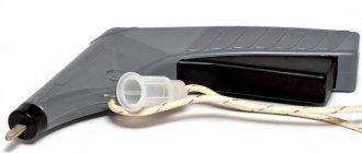
The Priora coil consists of a primary and secondary winding, between which a core is placed. To contact the spark plug, a spring is used, which is placed in a rubber tip. The IKZ also has a metal screen that protects the coil from high temperatures, because IKZ is installed in the well of the cylinder head, then the temperature conditions there are simply enormous. The primary winding is wound from thin copper wire with a number of turns of 10,000-15,000.
The secondary winding of the coil consists of 100-150 turns of thick copper wire. The connection between the coils is electromagnetic.
Version of the module on the 8-valve VAZ-2110
The top ten was equipped with two 8-valve engines of different sizes - 1.5 (2111) and 1.6 liters (21114). The ignition modules for these engines are different.
- The one and a half liter engine has a module with article number 2112-3705010,
- and the 1600 cc is equipped with module 2111-3705010.
A module for a 1.5 liter engine costs about 1500-2100, and the second one is 500 rubles cheaper.
Which is better?
SOATE devices manufactured in Stary Oskol have proven themselves to be the most reliable ignition modules.
Module structure
The module consists of two ignition coils and two high-voltage switch switches.
Inside the module there is a board with radio components and ignition coils filled with compound.
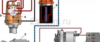
The coil generates a high voltage pulse, and it is a simple transformer with two windings, primary (induction voltage about 500 V) and secondary (induction voltage at least 20 kV). All this is assembled in a single housing, on which there is a connector for signal wires (from the engine control unit) and four terminals for high-voltage wires.
Schematic diagram of the module.
The module operates on the principle of an idle spark - it distributes sparks in pairs to cylinders 1-4 and 2-3 according to impulses transmitted from the ECU.
Signs of coil failure:
- One of the cylinders does not work;
- The car does not develop power;
- Jerking when pressing the gas pedal sharply;
- The engine shakes at idle;
- Increased vibration at idle;
- Floating speed;
It should also be noted that if the ignition coil is faulty, misfires will appear in the cylinders, as a result of which the ECU will turn off the operation of the faulty cylinder and signal this by turning on the “Cheek Engine” lamp. When “Cheek Engine” appears on the car, it is necessary to diagnose the system. If there are misfires, the ECU will display errors 0301, 0302, 0303, 0304. Where the last digits of the codes are the cylinder number. It is not recommended to operate a car with a faulty ignition coil; this can lead to failure of the catalyst.
Checking the ignition coil
There are two reliable ways to check IKZ: visual inspection and checking with a multimeter.
It should be noted that the IKZ check is similar for all Lada cars with a 16-valve engine, i.e. the check for cars such as LADA Vesta and X-ray will be the same.
In order to check the ignition coil, it must be removed from the car. Removing IKZ:
- Disconnect the negative terminal from the battery.
- Remove the decorative plastic trim.
- We unscrew the coil we need with a “10” or Torx E8 head.
- Remove the coil plug and remove it.
Checking and replacing the ignition coil on a VAZ 2112
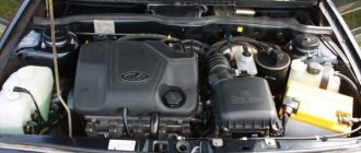
The ignition coil of the VAZ 2112 engine is the main part of the car’s ignition system, which serves as a conventional low-voltage direct current converter, which comes from the battery or directly from the electric generator into high-voltage voltage for further supplying an electrical impulse to the spark plugs.
In today's article we will learn how to check the ignition module on an injection VAZ-2112 8 valve with our own hands, and also consider step-by-step instructions for replacing this car unit.
Visual inspection
After the coil is removed, it must be carefully inspected. The rubber tip should not have tears or cracks. The plastic part must not be melted or cracked. The contact spring must be in the correct shape without oxidation or rust.
Crack in the coil Cracks in the coils or tears in the rubber cap will direct the spark to the engine body, therefore, no current will be supplied to the spark plug, which will lead to misfires.
Cracks in the elastic band of the coil If such visual faults are detected, the coil must be replaced.
Checking with a multimeter
Testing with a multimeter is divided into two stages. Checking the resistance of the IKZ itself and checking the control voltage of the IKZ (checking the voltage on the IKZ power supply block).
Let's start by checking the voltage at the IKZ power supply.
To do this, set the switch on the multimiter to constant voltage.
Turn on the car ignition
On the block in connector number 3 we take a measurement (we connect one multimeter probe to the motor body and the other to pin number 3) the voltage should be at least 12 volts. If the voltage is less, this means that the battery is discharged or the ECU controller is faulty.
Checking the IKZ resistance
In order to check the resistance of the IKZ, you need to use a multimeter. It should be noted that resistance measurements must be carried out on a cold engine, because The resistance of the coil windings strongly depends on its temperature. To check the resistance, it is necessary to check two windings, the secondary and the primary.
Checking the primary winding of the IKZ When checking the primary winding of the IKZ, it is necessary to set the resistance readings on the multimeter, namely 200 Ohms. Since the resistance readings on the primary winding are not large, and the error of the device is possible, you first need to find out the error of the multimeter. In order to find out the error, you need to close the probes together, the value that will be reflected on the multimeter screen will be the error.
In this case, the error of the device is 0.7 Ohm. Next, we connect the multimeter probes to contacts 1 and 3 (the outermost contacts of the IKZ) and obtain resistance readings. From these readings we subtract the multimeter error and get the true value of the resistance of the primary winding.
Ideally, the resistance of the primary winding should be about 1 Ohm, or better yet 0. In this example, the reading is 1.1 Ohm without taking into account the error; from 1.1 Ohm we subtract 0.7 Ohm to get 0.4 Ohm. Verdict: the primary winding of this IKZ is in working condition.
Checking the secondary winding of the IKZ In order to check the secondary winding of the IKZ, set the multimeter to 2000 kOhm.
We connect the red multimeter probe to the spring, and the black one to the middle contact on the IKZ (pin 2). We look at the readings of the device; on a working coil, the resistance of the secondary winding should be in the range of 300-400 kOhm.
As we see, the readings of the secondary winding are also within the normal range. It follows that this IKZ is working.
If the readings are too high, you can try removing the rubber cap and spring from the coil and cleaning the contact patch, then measure the resistance directly again without the spring. If the resistance reading still does not decrease, you should think about replacing the ICP.
The easiest method to detect a faulty ignition coil, without any devices or instruments. This is a reversal of the IKZ.