Let's start to disassemble
First, drain the oil and antifreeze. We remove the protective cover, the air filter with pipes, disconnect the ignition coil connectors, the throttle cable and the throttle assembly.
We remove the thermostat housing and simultaneously disconnect all the available connectors and pipes. We remove all the wiring that was in our way towards the battery.
We remove the generator. We unscrew the eight thirteen nuts holding the intake manifold and remove it. We unscrew all the bolts securing the valve cover, as well as the side engine support.
Unscrew the eight nuts and remove the exhaust manifold.
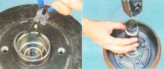
Remove the timing belt, camshaft pulleys and pump.
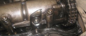
In three passes, so as not to deform the part, we first loosen and then unscrew twenty bolts of the camshaft bearing housing, the head is eight. Be sure to follow the sequence shown in the photo.
Remove the bearing housing. We remove the camshafts; there is a distinctive lip on the intake camshaft.
Also, in several passes, we first loosen and then unscrew the ten cylinder head mounting bolts. Be sure to follow the sequence shown in the photo.
Remove the cylinder head. All sixteen valves are replaced.
Sparco24 › Blog › Installing 16V camshafts
In this article we will look at the installation of sports and tuning camshafts on VAZ 2112, 21124, 21126 and 11194 engines. First, you need to remember that engines 2112 and 21124 have their own timing belt drive and are incompatible with the timing belt of engines 21126 and 11194 - this worth considering when purchasing split gears. Engine gears 21126 and 11194 have rounded teeth, so the belt, pump, lower crankshaft gear and camshaft gears have their own. To install the camshafts you need to do the following:
1. Disconnect the TPS, IAC and mass air flow sensor connectors, loosen the clamps holding the inlet pipe on the receiver, loosen the ventilation clamp for the crankcases of the cylinder head cover and dismantle the intake pipe assembly with the mass air flow sensor;
2. Unscrew the nuts that secure the receiver to the cylinder head; it is most convenient to do this with a ratchet with a 13-mm socket;
3. Remove the receiver assembly with the throttle;
4. Remove the timing belt cover using a ratchet and a short 8mm socket;
5. Loosen the bolts of the camshaft gears;
6. Set the crankshaft position to TDC of cylinder 4, aligning the mark on the flywheel and, loosening the tension roller, remove the belt from the camshaft gears;
7. Completely unscrew the bolts of the camshaft gears and remove the gears themselves. Be careful - the keys for fixing the gears on the camshafts can fly out and, due to their small size, can easily get lost;
8. Using a ratchet and a 8mm socket, unscrew the timing cover bolts and remove it. Using the same tool, unscrew the bolts of the bed and also dismantle it;
Cylinder head repair
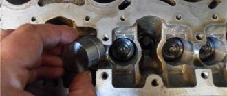
We mark all hydraulic compensators with numbers using an ordinary clerical touch and put them away. An ordinary magnet will help you pull them out. We dry out the valves and remove the oil seals (valve seals), the valves into scrap metal, the oil seals into the trash. We clean all channels. We take the head for grinding, just in case. After washing it again with kerosene after sanding and blowing it with air, we begin to assemble it.
We arrange the freshly purchased valves in the sequence in which they will stand in the cylinder head and begin to grind in one by one. Lubricate the valve stem with clean oil and apply lapping paste to the edge.
We insert the valve into place and put a valve grinding tool on the valve stem. The stores sell a device for manual lapping, but since this is the twenty-first century, we are mechanizing the process. We take the old valve and cut off the rod from it, select a rubber tube for it of such a diameter that it fits tightly. The rod is in a reversible drill, one end of the tube is on it, the other is on the valve being ground in. At low speeds we begin to grind the valve, constantly change the direction of rotation and periodically press it to the seat or weaken the force. On average, the valve takes about twenty seconds. We take it out and wipe it. The valve is considered ground in if a uniform gray strip of at least 1.5 mm wide appears on the chamfer.
The same stripe should appear on the valve seat.
Video of manually grinding valves
For a sixteen valve head, everything is the same, only there are twice as many valves. After lapping, all valves and seats are thoroughly wiped and washed with kerosene to remove any remaining lapping paste. We check for leaks. We tighten the old spark plugs and put all the valves in place. Pour kerosene and wait three minutes, if the kerosene does not run away all is well, otherwise we grind the valves on this cylinder.
We had to grind four valves again, after which the kerosene stopped flowing.
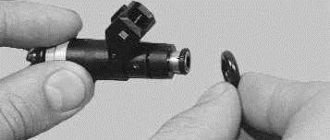
We stuff new valve seals.
We put the valves in place and dry them. Before doing this, lubricate the valve stems with clean oil. After lubricating it with clean oil, we put the hydraulic compensators in place and, covering them with a clean cloth, remove the head out of sight. We're done with the cylinder head.
Malfunctions and repairs of the VAZ 2112 engine
The VAZ 2112 (21103) engine is a qualitative evolution of the VAZ 2111 engine, but with 16 valves instead of 8 and gave rise to a series of VAZ gears that are produced to this day, already in the form of a prior engine. The main differences between the 2112 engine and the 2111 are the use of 4 valves per cylinder, 2 camshafts, this allows the engine to supply more fuel-air mixture to the combustion chamber at a time and quickly remove exhaust gases to the exhaust channel. Up to 3 thousand rpm, the engines operate approximately the same; after 3 thousand, 16V becomes much more dynamic. At the same time, fuel consumption is lower than on the 8 valve 2111. Engine VAZ 2112 1.5 liters. injection in-line 4-cylinder with an overhead camshaft, the gas distribution mechanism is belt driven. Cylinder block 2112, the same as on 21083, but with modified mounts under the cylinder head and additional oil channels for the main bearings, the VAZ 2112 engine number is stamped on the block under the thermostat. The normal operating temperature of the 2112 engine is 90 degrees. The service life of the 2112 engine, according to the manufacturer’s data, is 150 thousand km; in practice, the engines run more than 250 thousand km. The other side of the coin is the VAZ 2112 engine, when the timing belt breaks, the valve bends. The problem is solved by installing pistons from a 124 engine, but we will inevitably lose a few horsepower. If you do not want to lose power, you need to constantly monitor the condition of the belt. To do this, we listen to the sounds coming from the drive; the rollers usually begin to squeak when cold, then rustle, and then collapse. The pump begins to leak (the belt will be covered in coolant). The shaft seals are leaking (the belt is covered in oil). The shafts wear out - the belt begins to slide to the side and rub against the roller flange (grinding when cold). The belt can also slip due to crooked rollers. Problems and malfunctions: the 2112 engine is throttling or adjusting - measure the compression, is it normal? Check the ignition module, high-voltage wires and spark plugs, these are the main problems in this case. The engine speed of the VAZ 2112 1.5 floats, the following should come under suspicion: the throttle valve (clean), Idle air control, crankshaft position sensor, throttle position sensor (check, change) or not? Then the DMRV is to blame. The following malfunction, at idle and when driving (when changing gears), the 2112 engine stalls, the problem is in a dirty throttle valve, or in the IAC (idle speed control), possibly the TPS (throttle position sensor). Let's look further, engine 2112 does not start, what is the reason? The first is the starter and battery, the second is the ignition system, the third is the power supply system, if you can’t hear the fuel pump running, check its power supply, is everything okay? Check the pressure in the fuel supply system. Another malfunction, the VAZ 2112 engine does not heat up or does not heat up well to operating temperature, the thermostat has died, change it and drive without problems. What next, do you hear some kind of knocking noise in the VAZ 2112 engine? Almost always the problem is with hydraulic compensators. If they have nothing to do with it, then the oil pressure is low or too high, or the connecting rod or main bearings are knocking, and the pistons may also be knocking. In this case, it is better to go to a service center for diagnostics. It’s better to go for diagnostics and in the case when the VAZ 2112 engine pulls poorly, here you need to measure the fuel pressure in the rail, maybe it’s a problem with the injectors, maybe the filters are clogged, or maybe the clutch has just arrived. That's not all :) Can you feel the vibration of the VAZ 2112 engine? The problem is: idle air control, high-voltage wires, spark plugs, lambda probe, voltage regulator, clogged injectors, incorrect ignition timing. The list is decent, so as not to guess and waste time, let's go for diagnostics.
Let's move on to the cylinder block
We remove the pallet. Rotating the crankshaft as it is convenient for us, unscrew two bolts on each connecting rod cap. We use a TORX E10 head for this.
We take out the pistons along with the connecting rods. To do this, use the wooden handle of a hammer to press the connecting rod from below and lightly tap it to knock it up. We remove the old liners and buy new ones of the same size according to the markings on them. Here is another stone in AvtoVAZ’s garden, the owner has never climbed into the car from the interior or into the engine, but three pistons were of group “B” and one was “C”. It turns out that at the factory they re-sharpened one cylinder a little and simply put an enlarged piston there, no words. There are no options, we take group “C”, don’t sharpen the engine because of this. We will not touch the main liners either.
Engine assembly
We wipe the crankshaft journals, cylinder bores and connecting rod bearing seats with a clean rag; by the way, they can also be degreased. We put new liners into the connecting rod and the cover, so that the antennae of the liners fit into the grooves.
Lubricate the bearings, crankshaft journals and cylinders with clean oil. We unfold the piston rings with locks as shown in the figure, the angle between them should be 120 degrees.
We put a mandrel on the piston to compress the rings, having previously lubricated it inside with clean oil. Not forgetting about the direction, the arrow on the piston should be directed towards the front of the engine, we place it in its cylinder.
We turn the crankshaft so that the connecting rod journal is at the very bottom. Gently tapping the wooden handle of a hammer pushes the piston into the cylinder. We remove the mandrel and push the piston down until the connecting rod sits on the crankshaft. We put the connecting rod bearing cap on the bottom, remembering the marks. Tighten the connecting rod cover mounting bolts to a torque of 5 kgf*m. We also repeat with all the other cylinders.
We put back everything that we removed from below. We blow through the top and clean the holes for the cylinder head mounting bolts. We install a new cylinder head gasket and the head itself. Lubricate the bolts with a thin layer of oil, most importantly without fanaticism. We tighten the bolts in several passes in the reverse order of unscrewing, see photo at the beginning of the article. The tightening sequence is as follows:
- first tighten everything with a torque of 2 kgf*m
- then we tighten everything to a torque of 7 – 8 kgf*m
- turn it 90 degrees
- turn it 90 degrees again
We install hydraulic compensators, camshafts and camshaft bearing caps. Lubricate all rubbing surfaces with clean oil. Before installing the camshaft bearing caps, lubricate the perimeter and rims around the spark plug wells with a thin layer of sealant. We tighten the bearing cover bolts in the reverse order of unwinding, with a torque of 2 kgf*m, see photo at the beginning. Well, then we install all the parts in the reverse order of removal. We fill in all the fluids and start it, it may not start right away, this is normal. When you first start it will smoke well until the oil on the cylinders burns, make sure the oil pressure light goes out. Let it run for a minute and turn it off, and suddenly see where something is leaking. We start it several more times, constantly increasing the operating interval, bring it to operating temperature, constantly checking the oil and antifreeze, and also pay attention to the fact that no extraneous noise appears. Let it rest for an hour and then idle again for about an hour, constantly monitoring the temperature. Well, then the break-in, if you sharpened it, if not, then you can drive only the first thousand kilometers, try not to raise the speed above 3000, and not tow it.
In what cases is it necessary to tighten the block?
During the operation of any car, including the VAZ 2170 Priora, the engine head is exposed to long-term cyclic effects of gases located in the engine cylinders. On older power units, the tightening of the cylinder head screws could weaken under such loads and periodically needed to be brought to a normal level. Today, all VAZ Priora engines use bolts made of special steel, which are tightened once for their entire service life.
If a coolant and oil leak occurs, there is no point in further tightening and tightening these bolts, since this will not improve the tightness of the joint. The only correct way to combat a leak is to remove the head, check the evenness of the mating surfaces and replace the gasket. After performing any repair work related to removing the head from the engine, it must be tightened in compliance with all necessary conditions.
The video from the author Alex ZW shows the process of installing the cylinder head on an 8-valve engine.
crank mechanism
This main engine unit consists mainly of the following groups:
Each part of the group has several additional elements. For example, each piston carries a set of O-rings, a connecting pin and pin retaining clips. The crankshaft has bearings and oil seals. The most interesting thing is the structure of the connecting rods.
The principle of operation of the mechanism
VAZ engines, like other cars, are based on explosive combustion of fuel. The piston creates a certain compression of the air-gasoline mixture, a spark from the spark generator ignites it, pushing the piston down, and the crank mechanism (CPM) converts translational motion into rotational motion. This occurs due to the special shape of the crankshaft. The mounting points of the connecting rods are located so that while the connecting rods pushing the pistons rise, the connecting rods pushed by the piston are lowered. And this process takes place in shifts.
Set of connecting rods "Priors"
These parts are collapsible. The main part is made of high quality metal. Only in the upper ring, where the piston locking pin fits, is an insert made of a different metal installed. In general, the connecting rod consists of the following parts:
- connecting rod;
- liner covers;
- coupling bolts 2 pcs.;
- special washers;
- connecting rod bearing.
This is due to the fact that the liners have special grooves for the passage of engine oil. Due to the high rotation speed, this unit requires uniform and abundant lubrication. The slightest discrepancy between these grooves and the oil supply holes of the crankshaft will lead to a disruption in the flow of lubricant and, as a result, jamming of the engine.
Video “How to properly tighten cylinder head bolts”
In this video, a master with extensive experience shows and describes in detail how to properly tighten the cylinder head bolts. On a Lada Priora car with a 16-cl unit, work is performed according to the same scheme.
We discussed disassembling the engine in the article - “Disassembling the VAZ-21126 engine”
The engine parts were defective in the article - “Defective parts of the VAZ-21126 engine.”
You will need: a torque wrench, a hammer (preferably with a soft metal or polyurethane striker), a device for installing pistons into cylinders, the same keys as for disassembling the engine, a screwdriver, a mounting spatula.
Clean carbon deposits along the edges of the cylinder block beds.
Clean the oil grooves in the beds from deposits.
Install the main bearing shells in the cylinder block bed in accordance with the marks made during disassembly.
When installing the liners, their locking lugs must fit into the grooves of the beds.
Lubricate the bearings with engine oil.
Priora connecting rod dimensions
By pushing the piston up to its entire length, the connecting rod strictly fixes the volume of the combustion chamber. From this we can conclude that the volume of the working cavity of the cylinder itself, in which the fuel burns, also depends on its length. That is, if the length is increased, the volume will become smaller. And if you shorten it, the size of the camera will increase accordingly. The factory engine comes with standard length connecting rods. It is 150 millimeters. It is measured from the axial point of the center of the head (pin attachment) to the same line of the lower part attached to the crankshaft. This size provides the motor with standard factory parameters. For example, engine displacement. It is 1597 cubic centimeters. Or as the owners say, the engine is “one and six”.
Engine tuning using connecting rods
Most young people who purchase a Priora are not satisfied with the factory parameters of the car. Many people strive to improve their car. Make it more powerful, more responsive and faster. This is called "charging" the engine. That is, as they also say, make tuning. This concept includes many different actions. This includes the installation of special camshafts, and the lightweighting of various parts, the flywheel and others. And much more. This category also includes the installation of special shortened connecting rods, which accordingly increases the volume of the working combustion chamber of the Priora engine.
The most popular for such an operation are the so-called “sports” reinforced connecting rods, 131 mm long. They are included in the standard kit for improving the Priora engine.
Removing and installing connecting rods on the Priora engine
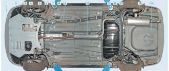
The interesting thing is that, although this part is located almost in the middle of the engine, it can be removed without removing the engine from the car. Yes, this is, of course, not an easy operation, but it is quite doable. It must be carried out either in an inspection hole or on a special lift for cars so that there is access to the oil pan. When the vehicle is positioned for surgery, the engine compartment protection underneath is removed first. The cylinder head, engine sump and flywheel are dismantled. It is advisable to remove the oil intake so as not to damage it. You can start removing the connecting rods.
It is worth starting from the first cylinder. This is in order to put the details in order and not get confused. Rotate the Priora crankshaft so that the lower part of the connecting rod is level in the lower position. Unlock and unscrew the bolts securing the liner cover. Remove it and set it aside along with the liner itself. After this, push the piston up and remove it from the cylinder. One by one, remove all the Priora pistons and connecting rods in this manner. Now you can repair or replace elements.
Torque and sequence of tightening the camshaft bed
Camshaft cover tightening sequence
Correct tightening of the camshaft bed, as well as other parts of the cylinder head, determines the normal functioning of all components and assemblies. So, in order to tighten threaded connections, a standard tightening pattern and a torque wrench are used.
Before installing the bolts in place, they must be washed thoroughly and lubricated with silicone grease.
In order to properly tighten the bolts, you need to know the sequence. It starts from the middle part and gradually moves directly to the edges. The detailed sequence can be seen in the photo below.
Tightening diagram for each camshaft bed bolt with numbering
As for the tightening force itself, it is 8.0-10.0 Nm . After the bed is installed on the block head, the connection bolts are tightened by hand or without much force using a ratchet with a head.
We tighten all the bolts by hand, but do not tighten them
When all the bolts are in place, you need to take a torque wrench and tighten them according to the standards in the order indicated above.
Torque wrench for tightening threaded connections
In what cases is it necessary to tighten the camshaft bed?
The bolts are tightened. Marked with arrows
Tightening the camshaft bed will be necessary if it was previously dismantled for restoration and repair work. So, in what cases will you need to remove the bed, let’s look at it in more detail:
- Replacing camshafts, lifters or valve seals.
- Overhaul of the block head.
- Engine repair operations.
- Replacement of individual elements of the cylinder head.
Consequences of improper bed tightening
The consequences of improperly tightening the camshaft bed include the following:
- Oil leakage due to a gap or loose connection.
- Passing air inside the cylinder head.
- Malfunction of the engine or cylinder head.
- Ingress of foreign objects (water, dirt, dust).
Installation
Place the prepared groups in place also through the top of the cylinder. Carefully check and replace the connecting rod bearings. Install the lower elements - covers, and secure with bolts.
This is due to the fact that a lot depends on the tightening torque: both the freedom of rotation of the crankshaft, and at the same time the tightness of the fit of the liners to the neck of this shaft. If it is weak, oil will leak out without proper lubrication, and if it is strong, it will jam and, again, insufficient lubrication. Based on these considerations, this value should be exactly 43.32-53.51N*m or another 4.42-5.46 kgf*m. Only this way and no other way. After this, you can perform complete assembly in reverse order.
Interesting video about Priora connecting rods:
Sometimes it happens that it is necessary to urgently replace the gasket or change the cylinder head. Such work at a service station costs a lot and to save money, you can try it yourself. This work is not difficult, but requires care; the main thing is to observe the sequence and tightening torque of the Priora cylinder head of 16 valves.
Here you also need to know that the tightening sequence on 16 cl and 8 cl units is different, so you need to be careful. The torque on the 16 and 8 valve power units is the same and passes in four circles.
Adjusting the tightening torque of bolts for a 16 valve car
Adjusting the tightening torque is a simple process, and after reading the material and video in this article, you can handle it yourself. It is enough to tighten it once and then you will be able to do it yourself and at the same time you will be able to help your friends if necessary. It is important to adhere to the diagram for cars with a 19-valve engine and observe the timing.
- a set of keys;
- a torque wrench (no need to buy it, it’s better to borrow it for a day or two);
Torque wrench - knob;
- rod compass;
Shtengel compass - socket heads.
The pattern for tightening on a 16-valve engine differs from the pattern for an 8-valve engine, so we will present both one and the other so that you can compare them.
Diagram for 16 valves Diagram for 8 valves
Just don't get confused when you install. In any case, before starting work, check the instructions that came with the car. Tightening with different torques on a 16 valve unit occurs in 2 circles with different torques, and then another 2 circles with a rotation of 90 degrees. Nothing is difficult, which means you can cope on your own.
In order for self-tightening of bolts to be completed successfully and to last for a long time, a number of simple rules should be followed:
- It is better to use new bolts, since during operation they are under constant tension and lose their properties over time. There is no guarantee that the old bolt will not withstand the stress and will burst.
The length should not be more than 9.5 cm - It is not advisable to reinstall the gasket, even if it is in reasonable condition.
- Strictly observe torque when tightening.
- The sequence of tightening the bolts should be exactly the same as in the diagram for 16-valve power plants.
- Before installing the cylinder head, carefully inspect all parts for damage and deformation. If any are found, do not ignore them, but be sure to replace them. Often, small breakdowns lead to major damage, and sometimes even to the complete destruction of systems and mechanisms.
- Do not use tools of dubious quality and manufacture. This is especially true for a torque wrench.
By following these simple rules, you can guarantee the best tightening and a reliable tight connection.
Place the cylinder head on the block, first making sure that the crankshafts and camshafts are set to the top dead center (TDC) position.
Proper twisting
The tightening process itself takes place in 4 circles:
- 1st circle - moment 20 N m (2 kgf/m);
- 2nd circle - moment 69.4–85.7 N·m (7.1–8.7 kgf·m);
- 3rd circle - turn the bolts 90 degrees;
- 4th circle - another 90 degree turn.
As you can see, everything is simple. If you have any questions, watch the video. In terms of time, this work does not take more than twenty minutes, but it allows you to save a decent amount, which they will charge you at the service station.
Loading …