Last week I drove the car on business and didn’t like the fact that the idle was floating - it either dropped to 500, then jumped to 1500, the engine shook at idle. But at the same time it drags normally, without failures. Checking the ignition by ear” using the well-known method - giving full throttle in 4th gear at a speed of 60 showed that the ignition is set correctly. So you need to look at the carburetor. And today, Sunday morning, the weather turned out to be good, sunny, I decided to see what was wrong with him. (By the way, it’s snowing outside now!).
To begin with, I studied on the Internet the description of the carburetor, its design, what is connected where. In principle, the K-151 is very similar to the Zhiguli “ozone”, it also has an autonomous idle system, an EPHH economizer controlled by almost the same control unit (externally the same) and the same solenoid valve. In general, I figured it out, nothing too complicated.
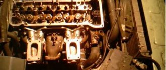
So I remove the “pan” and see... well, to put it mildly, the carburetor needs to be removed and cleaned - it’s overgrown with carbon deposits and dirt, but that’s for later. And now, for preventive purposes, we need to replace the fuel hoses, which are all cracked from old age, and we’ll try to adjust them.
The first thing that surprised me was that there is no vacuum tube on the economizer. It’s strange, because then there shouldn’t be any idling at all. Or rather, it is there, dangling nearby and plugged with a screw inserted into the tube. Oh, here it is - the former owner decided to simplify the system - instead of the throttle stop plug, he inserted a long pin, screwed two nuts onto it and made an idle speed regulator screw out of it, regulating the degree of opening of the throttle valve. Here I am just twisting it with my hand.
In fact, the idle system did not work at all, and the engine idled because the throttle valve did not close completely. The previous owner was probably a Solex fan, but the transition system of this carburetor is not designed to maintain even and stable speeds, so the speeds float. And the motor was shaking because the quality screw was screwed in all the way, but there was no o-ring on it, so the motor responded poorly to attempts to adjust due to the lack of a rubber ring on the quantity needle. There was an EPH system here, but it was eliminated - there is an electronic valve, but there is no microswitch on the carburetor. If desired, the system can be restored, but for now we will assemble and adjust as necessary at least what we have. To begin with, I put a vacuum tube on the economizer (in the photo it is already put on, but not the one in the foreground, but below, take a closer look. The one in the foreground is part of the USR system, and then...
I went to my nearest parts store. Yes, among the spare parts for the Volga there is only an air filter, but the fuel hoses and the rubber ring of the propeller are quality ones that can be supplied from a Lada, and the clamps are a universal thing. I bought 2 quality sealing rings for the needle (one in reserve just in case), a long fuel hose, the “return” hose from 2108 was perfect for the “return” and on the Volga, and clamps for them.
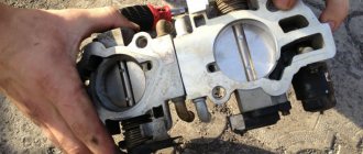
First, I removed all the old fuel hoses and pulled out the fittings. This is how tired they are:
On the Volga, the fuel supply hose is very serious, not just on clamps, but also on metal fittings, tightened with a wrench “14” (hello Volga, in Lada cars everything was mostly “13”, I read somewhere that the fasteners “13” actually came to the USSR with Zhiguli cars, before that there were no such sizes, they somehow managed with “12” and “14” sizes). I tried on the long fuel hose in place and cut it into two parts, put it on the fittings, tightened the clamps and installed it.
For a long time I thought about leaving this authentic “glass” - a fine filter or installing a regular plastic filter. Then I decided not to violate the authenticity - let it be, then I’ll replace the actual filter element in it and okay. Next I set the return line. A good system, the fuel pump does not pump “against the wall”, but works constantly, dumping excess fuel back into the tank. This eliminates the possibility of the fuel pump overheating and failure due to a vapor lock, which often happened on Zhiguli cars.
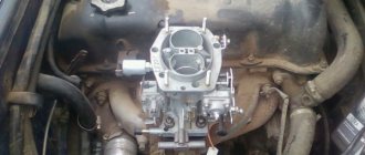
Now we remove this collective farm with the idle regulator using the throttle stop. Instead of this stud I put a screw with a lock nut. I tighten the screw so that the throttle valve stop is only slightly supported, so that the valve closes completely against this screw, and in this state I fix it with a lock nut.
And now the engine is already purring at idle, steam and water are coming out of the pipe. In general, anyone who has ever seen “live” how a normally adjusted 402 engine works at idle will understand what kind of song this is. The impression is that the revolutions are generally low, the crankshaft seems to barely rotate, but according to the instrument everything is correct - 700 revolutions (approximately). That is, the tachometer needle is slightly below 1000.
Now we turn on the headlights, the heater fan to full and the heated rear window and see how the engine will work under the load of the generator and how much the speed will drop. If they sag a lot, then add the quantity with a screw; if the engine also shakes, there are interruptions, then you can add not by quantity, but by quality. That's basically all science is.
Despite the apparently terrible condition of the carburetor, it was adjusted normally. The engine “whispers” at idle and picks up speed without any dips. In general, it’ll do, I’ll put the “saucepan” in place.
Another thing that was noted along the way is that there is a new pump on the engine; it stands out sharply due to its novelty against the background of other parts. It looks like the previous owner forked out money for it to get from the Lipetsk region to Moscow without problems. The old one seemed to pump very poorly, so there is an additional pump in front of the stove faucet, the same one I once installed on the Omega when I froze in it in the winter. True, I couldn’t find where it turns on, but the stove heats normally even with it not working. Moreover, there is also a faucet to expel air pockets (part of this can be seen in the photo where I unscrew the throttle stop). Most likely, then I’ll remove this whole collective farm, replace the standard Zhiguli faucet with a ceramic one, which I liked on the Zhiguli, and the air temperature in the car can be adjusted using the regulator handle, and not just by lowering the window.
This is interesting: Timely replacement of engine oil is the responsibility of every driver
The radiator commands respect with its appearance. When making repairs under the hood, it is convenient to place screwdrivers on it; there are various fasteners - it will not fall anywhere, just like the shelf is wide and has sides. The upper fitting seems to be soldered, but with the cooling hoses there is generally some kind of collective farm - tubes, adapters, clamps, the hoses themselves are already made of oak, they are all cracked, one hose is pinched too much at a bend. In general, I will order new hoses and then replace them along with the antifreeze. The fact that the former owner only changed the pump and screwed such terrible old hoses onto it also indicates that he was already taking the car for sale.
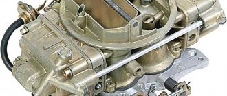
Design and principle of operation, diagram
The carburetor is designed for high-precision dosing of the air-fuel mixture and its subsequent delivery to the engine cylinders.
The K-151 carburetor has 2 parallel channels through which purified air from the filter passes. Each of them has a rotary throttle (damper). Due to this design, the carburetor is called a two-chamber carburetor. And the throttle drive is designed in such a way that, depending on the force of pressing the gas pedal (i.e. changing the operating modes of the internal combustion engine), the first damper is opened alternately, and then the second.
In the middle of each air channel there are cone-shaped constrictions (diffusers). Air flows pass through them, due to which fuel is sucked through jets from the float chamber.
In addition, the carburetor contains the following components:
- Float mechanism. It is designed to maintain a constant fuel level in the float chamber.
- Main dosing systems of the primary and secondary chamber. Designed for preparing and dosing the air-fuel mixture for engine operation in different modes.
- Idle system. It is designed to operate the engine at minimum stable speeds. Consists of specially selected jets and air channels.
- Transitional system. Thanks to it, the secondary camera is smoothly activated. Operates in transition mode between idle and high engine speeds (when the throttle valve is less than half open).
- Starting device. Designed to make it easier to start the engine in the cold season. By pulling out the choke rod, we turn the air damper in the primary chamber. Thus, the channel is blocked and the necessary vacuum is created to re-enrich the mixture. At the same time, the throttle valve is opened slightly.
- Acceleration pump. A fuel supply device that compensates for the supply of a combustible mixture to the cylinders when the throttle is opened sharply (when air flows are faster than the mixture).
- Econostat. Dosing system of the secondary mixing chamber. It is a sprayer through which additional fuel is supplied to the chamber when the throttle is fully open (when the air flow rate in the diffuser is maximum). This eliminates the leanness of the mixture at high engine speeds.
- Economizer valve (EPVH). Responsible for shutting off the fuel supply to the carburetor in forced idle mode (FID). The need for it is associated with a sharp increase in CO (carbon oxides) in the exhaust gases when the car is braked by the engine. Which has a detrimental effect on engine performance.
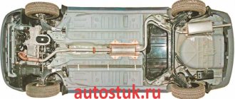
- Forced crankcase ventilation system. Through it, toxic gases from the engine crankcase do not enter the atmosphere, but into the air filter. From there they, with purified air, enter the carburetor for further mixing with fuel. But the system does not work at idle, because... There are not enough vacuum parameters for suction. Therefore, an additional small branch was invented. It connects the crankcase gas outlet fitting to the space behind the carburetor throttle, where the maximum vacuum operates.
Below is a detailed diagram of the K-151 carburetor with symbols:
Repair of components
Of course, the K-151 carburetor is far from ideal. For more efficient performance, its individual parts need to be straightened and polished. Let's talk about mating planes:
- the top cover, namely in the area of the float chamber;
- the middle part, where the surface is often curved due to the device being pulled towards the collector.
Accelerator pump repair
The accelerator system pump often comes to the repairman's attention after the car's dynamics drop. Dips appear, consumption increases - in the initial stages, from time to time.
If checking the pump gives the following results, you need to start repairing it:
- productivity below 8-9 cubic meters. cm;
- the presence of play in the pump foot, which explains the delay in fuel supply;
- the direction of the jet from the nozzle of the nozzle is crooked - it hits not the chamber, but the diffuser.
Repairing the K151 carburetor with your own hands in this case means proper tuning. Naturally, the cover of the device must be removed. Below are some useful tips:
- You can test the pump performance only with the carburetor removed. It should be filled with gasoline, then placed over a funnel with a beaker (a cut-off bottom from a plastic bottle will also work if you know how much it holds). Next, open the throttle and hold it in the open position for about five seconds. Then close for 1-2 seconds and open again. Repeat these operations ten times in a row. Check the volume of fuel collected in the beaker;
- It’s easy to direct the jet to the right place by sharpening the wall and turning the nozzle of the sprayer a couple of millimeters. The mixture should hit directly into the chamber, and not drip there or not fall at all. If there is no jet from the sprayer, you need to make sure that the discharge valve is working properly and the hole is clean. In general, it would be better to disassemble the diaphragm mechanism, wash its cavity and blow out all the channels with a stream of compressed air. The sprayer hole can be effectively cleaned with a piece of 0.3mm wire;
- The K-151D/S models are equipped with a double accelerator pump fuel nozzle. However, it is not needed in these carburetors, since the second chamber is closed. If this sprayer is installed for some reason (error), it will begin to pour fuel into the second chamber. When the valve opens, gasoline will flow into the manifold. This will cause engine failure. Therefore, it is recommended to replace this element with a single one. Or upgrade the carburetor, including a second chamber;
- When opening, the air damper must be in a strictly vertical position - 90 degrees! The slightest blockage will lead to increased fuel consumption;
- The leg is adjustable by slightly bending it. It should not have even the slightest free movement. A properly adjusted accelerator will begin to respond instantly.
Replacing the needle valve in the float chamber
As mentioned above, large amounts of fuel consumption may begin due to a faulty needle valve. To replace it, you need to do the following:
- remove the top of the carburetor;
- pull out the float shaft;
- remove the float with the needle;
- unscrew the valve seat;
- install new parts;
- put everything back together.
How to set it up yourself?
To adjust the K-151 carburetor you will need the following minimum set of tools:
- flat and Phillips screwdrivers;
- ruler;
- calipers;
- adjusting probes and drill (d= 6 mm);
- tire pump.
To dismantle the carburetor you will need open-end or ring wrenches for 7,8,10 and 13.
Before tuning, remove the top part of the carburetor and clean it of dirt and carbon deposits. At this stage, you can check the fuel level in the float chamber. This will be discussed in detail below.
The carburetor should only be removed if absolutely necessary! When blowing with compressed air and washing do not eliminate the consequences of jamming of dampers and contamination of jets (channels).
It is important to understand that a carburetor that is not too dirty works the same as a perfectly clean one. The moving parts in it clean themselves, and it is not easy for dirt to get inside. Therefore, it is often necessary to clean the carburetor from the outside, in places where large pieces of dirt stick to mutually moving parts (on the lever mechanism and in the starting system).
We will consider partial disassembly of the device with all adjustments and subsequent assembly.
Removal and disassembly algorithm
Step-by-step algorithm for removing and disassembling the K-151 carburetor:
- open the hood of the car and remove the air filter housing. To do this, unscrew and remove the top fastening, and then the filter element itself. Unscrew the 3 nuts securing the filter housing with a 10mm wrench and remove it;
- remove the plug of the EPHH microswitch;
- Having disconnected all the hoses and rods, use a 13mm wrench to unscrew the 4 nuts holding the carburetor to the manifold. Now we remove the carburetor itself. Important! It is better to mark the hoses and connection points before removal, so as not to confuse anything during assembly in the future;
- disassemble the carburetor. Unscrew the 7 fastening screws with a screwdriver and remove the top cover, not forgetting to disconnect the air damper drive rod from the lever;
- We wash the carburetor using a special cleaning agent. Gasoline or kerosene is also suitable for these purposes. The jets are purged with compressed air. We check the gaskets for integrity and, if necessary, replace them with new ones from the repair kit. Attention! Do not wash the carburetor with strong solvents, as this can damage the diaphragm and rubber gaskets;
- While the carburetor is removed, the starting device can be adjusted. If it is not working properly, starting the engine in cold weather will be difficult. We'll talk about this setting later;
- screw the carburetor into place along with the top cover. We connect the microswitch block and all the necessary cables.
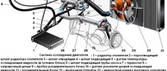
If you suddenly forget which hose to plug into where, we suggest using the following diagram (for the ZMZ-402 engine):
Connection diagram for carburetor hoses for ZMZ 402 engine
4- fitting for vacuum selection into the vacuum ignition timing regulator (VROZ); 5-vacuum sampling fitting to the EPHH valve; 6 – crankcase gas intake fitting; 9-vacuum sampling fitting to the exhaust gas recirculation valve; 13- fitting for supplying vacuum to the EPH system; 30- channel for fuel removal; 32 - fuel supply channel.
For the ZMZ 406 engine, a special K-151D carburetor is provided, in which there is no fitting number 4. The distributor function in it is performed by an electronic automatic pressure sensor (APS), which is connected by a hose to the intake manifold pipe, where it reads the vacuum parameters coming from the carburetor. Otherwise, connecting the hoses on the 406 engine is no different from the diagram presented above.
How to adjust the fuel level of the float chamber?
The normal fuel level for K-151 carburetors should be 215 mm. Before measuring, pump the required amount of gasoline into the chamber using the hand pump lever.
Fuel level control using the communicating vessel method
The level can be checked without disassembling the top of the carburetor (see figure above). A fitting with an M10×1 thread is screwed into place in place of the drain plug of the float chamber. A transparent hose with a diameter of at least 9 mm is put on it.
If the level is not correct, then unscrew the carburetor cap to access the float chamber. As soon as you remove the top, immediately measure the level using a caliper depth gauge (from the top of the carburetor to the fuel line). The fact is that gasoline quickly evaporates when exposed to the atmosphere, especially in hot weather.
An alternative option for level control is to measure the distance from the top plane of the chamber connector to the float itself. It should be within 10.75-11.25 mm. In cases where this parameter deviates, you need to carefully bend the tongue (4) in one direction or another. After each bending of the tongue, gasoline should be drained from the chamber and then refilled. In this way, fuel level measurements will be the most accurate.
Replacing the K-151 carburetor
If the parts are severely worn, the carburetor needs to be replaced; most often it is changed if the housing wears out:
- the lower surface of the middle part is severely deformed;
- the cover (upper part of the body) is warped;
- The seat for the throttle valves in the lower part wears out.
The price of a new K-151 carburetor is quite high (on average 5.5-6.5 thousand rubles), but it is impossible to drive with a faulty device, especially since with high fuel consumption even more money is lost. Changing the K-151 is quite simple; let’s look at the process of replacing it on a Gazelle car:
- turn off the engine, unscrew the air pipe clamp, dismantle the “corrugation”;
- dismantle the air filter housing - first the cover, then the main body (secured with three 10mm nuts);
- loosen the two fastenings of the choke cable, pull out the cable;
- disconnect the throttle cable;
- free the carburetor from all hoses;
- unscrew the 4 nuts that hold the device body;
- dismantle the unit - it can fit very tightly, so you can slightly pry it from below with a screwdriver, but you need to work with the tool carefully so as not to damage the gasket under the carburetor;
- We put the new carburetor in place, start and warm up the internal combustion engine, and adjust the idle speed.
Malfunctions and their elimination
Freezing of the economizer housing
The K-151 carburetor on some engines has one unpleasant feature. In humid subzero weather, the fuel mixture in the carburetor actively condenses on its walls. This occurs due to the high vacuum in the channels at idle (the mixture moves very quickly, which leads to a decrease in temperature and the formation of ice). The economizer body freezes first, since air enters the carburetor from here, and the flow cross-section of the channels here is the narrowest.
In this case, only drawing warm air into the air filter can help.
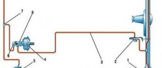
The trunk of the air intake hose can be thrown directly to the manifold. Or make a so-called “brazier” - a heat shield made of a metal plate, which rests on the exhaust pipes and to which the air vent hose is connected (see figure).
"Brazier"
Also, in order to reduce the risk of the economizer freezing problem, before the trip we warm up the engine to an operating temperature of 60 degrees . Despite the thermal insulation gasket from the engine, the carburetor still receives some heat.
Flange straightening
With frequent disassembly and removal of the carburetor, as well as with excessive force when tightening the flange to the engine, its plane may be deformed.
Working with a damaged flange leads to air leaks, fuel leakage and other serious consequences.
There are many ways to solve this problem. But the simplest and most accessible method is the following:
- We heat the plane of the carburetor flange using a gas burner. First, we remove all the components and parts of the carburetor (fittings, levers, etc.).
- Place the plane of the float chamber on a flat surface.
- As soon as the carburetor heats up, place a thick, even piece of hard metal on top of the flange. We don’t hit the piece too hard, moving it to different places each time. Basically, the bending of the flange occurs along the edges, in the area of the bolt holes.
Useful video
For more information about the method of straightening a flange, we recommend watching this interesting video:
To prevent further bending of the flange, simply tighten it evenly once to the engine and do not remove it again. As we saw above, the carburetor can be cleaned and adjusted without removing it from the engine.
Adjustment
The unit can be configured either with complete disassembly or without disassembly.
Adjusting carburetor 1107010 on UAZ:
Option 1.
- We start the car, warm up the engine;
- We unscrew the screw for adjusting the quality of the fuel mixture (the “quality” screw), and then screw it in 2.5 turns;
- Using the fuel mixture adjustment quantity screw (the “quantity” screw), we set the engine speed at 850–900 rpm.
- Use the “quality” screw to increase the speed;
- Using the “quantity” screw we return to the original mark;
- We carry out the operation until the engine speed increases when turning the “quality” screw;
- We stop manipulating the “quantity” screw after the speed begins to decrease (we set it at this mark).
- We check the functionality. If the car stalls when you sharply press or release the accelerator pedal, slightly unscrew the “quality” screw.
DAAZ-4178 can be configured both with and without complete disassembly
Option 2.
- We dismantle the carburetor and wash it well;
- We check the needle valve (if it is very worn, we replace it with a new one);
- We blow through all channels;
- We check the markings of the jets (factory markings for the main fuel jet, idle speed, transition system - 120, 48 and 60, respectively). If the numbers do not match, we change them to the corresponding ones.
- We check the air leak (install the unit, start the engine and close the air intake with your palm. If the engine stalls, there is no air leak).
- We configure the unit in the sequence of option No. 1.
Modifications
The K-151 carburetor was installed mainly on cars with ZMZ and UMZ engines with volumes from 2.3 to 2.9 liters. There were also varieties of carburetor for small-capacity engines UZAM 331(b)-3317. The letter designation on the carburetor body indicates that it belongs to a certain group of engines, depending on the parameters of the jets.
Calibration data for all modifications of the K-151 carburetor
The table shows that there are 14 modifications in total , the most popular of them are: K-151S, K-151D and K-151V. The following models are less common: K-151E, K-151Ts, K-151U. Other modifications are very rare.
K-151S
The most advanced modification of the standard carburetor is the K-151S.
The accelerator pump atomizer in it works on two chambers at once, and the diameter of the small diffuser is reduced by 6 mm and has a new design.
This solution made it possible to increase the dynamics of the car by an average of 7%. And the relationship between the air and throttle valves is now steplessly variable (see figure below). The choke can be turned on without pressing the gas pedal. New parameters of the dosing jets made it possible to comply with the current requirements of environmental standards.
Carburetor K-151S
K-151D
The carburetor was installed on ZM34061.10/ZM34063.10 engines, on which the ignition angle is controlled by an electronic brain.
The distributor has been replaced by a DBP, which reads the vacuum parameters from the exhaust gases of the exhaust manifold, so the K-151D does not have a fitting for collecting vacuum into the vacuum ignition timing regulator.
For the same reason, there is no microswitch for the EPH system on the carburetor.
K-151V
The carburetor has a float chamber unbalance valve with an electromagnetic solenoid. There is a fitting on the back of the chamber to which a hose for ventilation is connected. As soon as you turn off the ignition, the electromagnet opens access to the chamber and excess gasoline vapor escapes into the atmosphere , thereby equalizing the pressure.
The need for such a system arose due to the installation of a carburetor on UAZ export models, which were delivered to countries with hot climates.
Solenoid valve for unbalancing the float chamber on K-151V
The carburetor does not have the usual fuel outlet fittings and vacuum supply to the exhaust gas recirculation valve. The need for them will appear on later carburetor models with a standard fuel bypass system.
How to disassemble K-151
It should be borne in mind that there are quite a few varieties of the K-151 carburetor. However, the principles of disassembly and assembly are almost the same for everyone. Before starting dismantling, you need to mentally imagine the carburetor consisting of three main parts: the cover, the throttle body (middle part) and the bottom. These are the ones you need to work with:
- The top cover of K-151 is removed. It can be easily dismantled; just remove a few bolts.
The top cover of K-151 is easily dismantled
The diffuser on the K-151 is also removable
The screw on the side holds the axle with the float
The jet disassembly diagram will help you remove and reassemble everything correctly
The accelerator pump bolts are unscrewed with a flat-head screwdriver.
The throttle body is removed by unscrewing two screws
The throttle body is separated from the bottom of the K-151. There are two gaskets under the housing; they are also removable. The main components of the carburetor can be thoroughly disassembled, although this is not so necessary if you just need to clean the jets, holes and channels. Disassembling the carburetor is mandatory; if the jets are clogged, it is necessary to blow out or wash the internal parts of the K-151.
Design and procedure for adjusting UAZ K126G carburetors
The current condition of the vehicle is the main criterion for the performance of the machine components. The engine is considered one of the most important components of a car. UAZ models are equipped with carburetor-type power units (for example, the K126G carburetor), due to which the operation and adjustment of this type of vehicle is greatly facilitated in any mode of use.
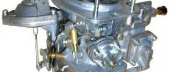
K126G carburetor design
Cars of the UAZ family are equipped with three types of carburetors. Each of these types has its pros and cons:
The most common equipment for off-road vehicles of the UAZ brand is a carburetor of the K126G type . This model is the basic equipment for the UAZ “Bukhanka” vehicles, and is also an invariable attribute of the equipment of the UAZ “Hunter” and UAZ “Patriot”. A carburetor of this type is ideally combined with the UMZ 4178.10 and UMZ 4218.10 power units.
A simple device for equipping power units of domestic off-road vehicles
The K126G carburetor consists of several main components:
fuel metering device for the first chamber;
fuel metering device for the second chamber;
idle mechanism.
In addition to them, the carburetor includes many small elements, each of which is designed to perform highly specialized work in the overall system.
The clear interaction of various elements allows you to achieve high carburetor performance
The K126G carburetor is equipped with two chambers for mixing the air-fuel mixture. After turning the ignition key, fuel begins to form in the first chamber, then, with increasing torque, in the second. Various elements of the system allow strictly limited amounts of liquid fuel and air to pass through to create the air-fuel mixture in the required quantity.
If the engine requires a higher mixture content at maximum speed, then the economizer is switched on. The solenoid valve increases air flow through a constantly open air damper, which ensures the creation of a rich mixture for the engine.
Features of operation of various carburetors
Theory is theory, but experience will tell you best about each model. It must be remembered that a carburetor is a relatively complex device characterized by its own operational characteristics. The most common ones include the following:
- The carburetor of the 126 model is simple and has a reliable design. This model is undemanding and can go without maintenance for a long time. Fine tuning allows you to adjust fuel consumption from 11 to 13 liters for every 100 kilometers;
- the K-126 model adds good dynamic characteristics to the vehicle;
- Model 469 is almost the complete antipode of the K-126 model. Firstly, even in urban conditions it spends almost 16 liters for every 100 kilometers. Secondly, the 469 model is extremely demanding in terms of quality and service. Even the slightest failure will worsen dynamic performance, acceleration speed, and so on;
- It should be noted that the 469 model also has a number of positive aspects. When installing it, the vehicle owner always manages to get an almost perfect start of the car;
- The DAAZ Solex model makes fuel consumption relatively low. However, this indicator remains so only under conditions of moderate driving speed. Any sudden acceleration or braking will make the single-chamber engine extremely power-hungry;
- Unlike the 469 model, DAAZ does not guarantee the vehicle owner always reliable and quick engine starting.
The process of adjusting K126G on the UAZ “Loaf”
Adjustment as a procedure may be required only to eliminate some malfunctions in the carburetor or to adjust for greater productivity. Adjustment can be carried out according to a variety of parameters to achieve optimal performance of the K126G carburetor:
stability in the operation of the accelerator pump;
setting a new minimum idle value;
quality control of fastening connections in the UAZ carburetor;
reduction of fuel consumption in different operating modes;
increasing/decreasing the specified fuel level in the float chamber;
checking the effectiveness of economizer operation;
adjusting the throughput of the jets.
It must be borne in mind that adjustments to any of the parameters are carried out only with the engine turned off. In different cases, you will need to wait for the power unit to cool down or, conversely, start the engine to adjust the required parameters.
For example, most often car enthusiasts adjust the fuel mixture consumption. The K126G device is designed in such a way that there is no need to disassemble the carburetor - all necessary work can be performed directly at the installation site of the mechanism.
Video instruction: adjusting K126G
Fuel consumption adjustment
There are two small quality screws on the carburetor body. Each of them controls the supply of a high-quality fuel mixture to the engine cylinders. And on the side of the throttle valve drive there is one separately located screw - it is called the quantity screw and is responsible for the required volume of fuel that is supplied to the power unit.
The procedure for adjusting the fuel mixture flow involves using these screws in the following sequence:
On a cold engine, tighten the quality screws until they stop.
After that, unscrew each of them exactly three turns.
Start the car and wait until the engine reaches its operating temperature.
After this, tighten the quantity screw and set the motor speed to about 600 rpm.
Start tightening the quality screw of the first chamber until interruptions in the operation of the engine become obvious (it will not have enough fuel).
After the first failure, unscrew the quality screw back about 1/8 of a turn (make sure the motor runs smoothly).
Make exactly the same adjustment with the quality screw on the second combustion chamber.
Then, using the quantity screw, set the required idle speed, the indicators of which were before (usually 900–1100 rpm).
Adjusting fuel consumption is not difficult to carry out. However, the car enthusiast must clearly understand the meaning of each of the actions performed so that the setting has the optimal result.
How to adjust the fuel level in the float chamber
After assembling the carburetor, you need to adjust the level in the float chamber. This is the very place on which the fuel consumption of the UAZ Bukhanka vehicle depends. You can adjust it yourself in the garage. To do this, the carburetor is installed in its regular place, tightened with nuts, and the top cover is unscrewed and simply pressed by hand. Insert the fuel hose and pump up gasoline using the manual fuel pump.
Fuel level in the float chamber
Now you need to lift the lid and put it aside, and use a ruler to measure the level in the chamber. It should be 21 millimeters. If the parameter differs from the nominal value, then you need to set the float position at which the level will always be maintained at the specified level and the needle valve will be in the closed position.
To do this, you need:
- Bend the float adjusting rods;
- Put the cover in place;
- Repeat level check.
The cycle is performed until the level in the float chamber is normal. By the way, you can see in detail how to do this in the video. After the level becomes nominal, you need to reassemble the carburetor. All attachments are installed on it, except for the air filter and its housing. It will interfere with adjusting the air damper drive. Installation is carried out in reverse order.
UAZ carburetor repair
Owners of UAZ cars, if they have the necessary experience and knowledge, can carry out some types of repair work on the carburetor themselves. After the carburetor has been removed and disassembled, you can repair its parts without going to specialized auto repair shops.
Many UAZ car owners are faced with the problem of carburetor flooding. That is, the device produces too much air-fuel mixture, which does not have time to get into the engine.
If the carburetor is flooded, it will be necessary to check the functionality of the economizer needle, and also make sure that the calibrated holes of the jets have not enlarged.
If the engine starts to twitch at high speeds or idles unstably, it is recommended to check the solenoid valve or economizer.
Repair of the UAZ K126G carburetor is entirely based on washing the components and replacing worn parts. At the same time, only three factors can be considered the key to quality repairs:
careful disassembly of the device;
assembly taking into account all the nuances of the K126G design.
Video instruction: modernization and repair of K126G
Troubleshooting
The K126G carburetor has its own characteristic faults. As a rule, they are all related to the fact that, for a number of reasons, the throughput of the jets is reduced, the life of the accelerator pump is exhausted, or gaps appear when the throttle valves operate. In addition, as with any other carburetor, the K126G may also experience an unbalanced idle speed, due to which the engine may flood or experience a lack of fuel.
The obvious reasons that certain malfunctions have appeared in the carburetor are:
a sharp increase in the amount of liquid fuel consumed;
at high speeds the engine operates jerkily and intermittently;
there were difficulties starting the engine;
uneven operating noise and increased vibrations during movement;
black exhaust smoke with a sharp increase in speed or during braking.
In carburetor mechanisms of any type, jets play an important role. According to their function, jets are plugs with several holes of clearly defined diameter. Air or liquid fuel enters through these holes, which guarantees the timely formation of the air-fuel mixture. Due to the use of low-quality gasoline, the jets can become clogged, causing the engine to lack fuel.
The main feature of the K126G carburetor is that all jets, regardless of their installation location, can be cleaned without dismantling. That is, in order to eliminate blockages in the holes, you will not need to completely disassemble the carburetor, since the jets are removed individually from the body of the device.
Table: performance characteristics of jets in different carburetor systems
| Carburetor elements | Nozzle capacity. cm 3 /min | Nozzle hole diameter, mm |
| Primary chamber | ||
| Main fuel jet | 240 ±3 | 1,05 |
| Main air jet | 195±4 | 0,94 |
| Idle fuel jet | 50 ±1,5 | 0,45 |
| Idle air jet | 285±7 | 1,15 |
| Acceleration pump nozzle | — | 0,6±0,06 |
| Accelerator pump with a capacity of at least 10 strokes | 5 | — |
| Secondary camera | ||
| Main fuel jet | 280 ±3,5 | 1,14 |
| Main air jet | 390 ±9 | 1,36 |
| Main jet of the transition system | 95±2 | 0,64 |
| Air jet of transition system | 285 ±7 | 1,15 |
| Economizer jet | — | 1,7 ± 0,06 |
| Economizer Sprayer | — | 3±0,06 |
Features of electrical equipment
So, what features does the UAZ 452 electrical wiring diagram have? At the time of the start of production, the most difficult moment for the engineers and designers of the enterprise was the search for the highest quality elements and components.
In particular, we are talking about parts for the vehicle lighting system, as well as ignition, which is especially clearly seen in how the car’s cabin is filled:
- control elements for various transport systems;
- control devices for monitoring the condition of components and mechanisms.
External optics
At that time, designers had to resort to many freelance solutions in order to establish mass production of cars.
- The UAZ electrical circuit includes an optics switch, which was borrowed from the GAZ 69. By the way, the latter is the predecessor of the Bukhanka.
- In addition, almost all the optics were borrowed from the GAZ 64 - these are lights, etc.
How to remove K126G from UAZ and disassemble it
The procedure for removing the carburetor mechanism is not particularly difficult. All hoses and lines connected to it are disconnected from the unit, after which the nuts that connect it to the intake manifold body are unscrewed. Once the nuts are removed, the carburetor is carefully removed from the studs along with the gasket.
A more complex procedure involves disassembling the device into its components. The main purpose of disassembly is to flush the internal cavities of the carburetor, as well as replace worn-out or worn-out parts. It must be remembered that disassembling the carburetor is possible only after thoroughly cleaning its body and external parts. For these purposes, it is recommended to use a special carburetor cleaner.
Disassembly procedure for K126G:
Undo the lever linkage fasteners.
Remove the end of the low speed rod from the opened hole.
Remove the seven small screws that secure the float chamber cover.
Carefully lift the cover and remove it. There is a gasket under it, you need to try not to damage it when removing the cover.
Next, remove the float axis and the float element itself from the chamber cavity.
The fuel valve needle is also pulled out along with the spring.
If necessary, you need to remove the air damper after unscrewing the two screws that secure it. Then the screw securing the drive lever bushing is unscrewed. The damper is pulled out without separating it from the lever and the return spring.
Next, unscrew the plug of the filter element and remove the filter mesh.
The next step is disassembling the float chamber itself. All components of the camera are carefully disconnected from each other and pulled out in a strictly vertical position.
After this, you will need to unscrew the plugs located on the outside of the carburetor body - this is the only way to remove the jets of the first and second internal combustion chambers.
Next, you can pull out the idle jet and the economizer valve itself.
Only the diffuser and the mixing section of the float chamber remained in the carburetor cavity. It is strictly prohibited to press small diffusers out of the carburetor, since their return installation in the desired position is almost impossible.
It is recommended to disassemble the device in a well-lit place
The procedure for cleaning carbon deposits
The formation of carbon deposits is typical, first of all, for three elements of the K126G carburetor:
float chamber containers.
Each of these elements, after disassembly, is subjected to washing, cleaning and purging using various technologies..
Jets require a special approach, since the slightest change in their surface and the calibration of the holes can cause unstable operation of the power unit. It is prohibited to wash the surface of the plugs. It is recommended to remove dirt and carbon deposits with a toothpick or copper wire, trying to come into contact with the metal surface as little as possible.
After cleaning, it is necessary to blow out the nozzle with compressed air from a can or through a compressor unit.
The air damper is easy to maintain - it can be placed along with other metal parts of the carburetor in a container with solvent 642 and soaked for two hours. After this, you need to dry the damper thoroughly and blow it to remove any remaining carbon deposits from the surface.
The float chamber can be quickly cleaned of carbon deposits, since you can pour carburetor cleaner into it and leave the liquid for an hour and a half. After this, you will need to wipe the chamber cavity with a soft, lint-free cloth to remove any remaining cleaner. You can also additionally blow out the internal surfaces with a can of compressed air.
Replacing the carburetor gasket
It is necessary to change the gasket if it has mechanical damage of any kind: cracks, tears, holes. The gasket serves as the only element between the carburetor and the intake manifold and performs two important functions:
establishes a high-quality connection between two units;
removes excess heat.
Replacing the K126G carburetor gasket is not particularly difficult: before installing the carburetor device on the manifold studs, you first need to lay a new gasket. The use of sealant or silicone is unacceptable, since when the temperature rises while driving, it will flow and can clog the holes in the carburetor.
The carburetor mechanism is placed on the gasket and secured with nuts to the cavity of the intake manifold. The gasket also serves to reduce friction between two metal surfaces, reducing vibration and noise during operating conditions.
The unique shape of the product allows you to firmly fix the carburetor in its workplace
Assembling and installing the carburetor in place
The assembly procedure for the K126G usually causes more difficulties than disassembly. The carburetor elements must be assembled in a clear order, otherwise it will be impossible to achieve stable engine operation.
Assembly is carried out as follows:
An economizer and an idle jet are installed in the cavity of the float chamber. The economizer is screwed on.
The fuel and air jets of the two combustion chambers are screwed into the outside of the carburetor body and screwed in until it stops.
The internal cavity of the float chamber is filled in the reverse order. It should be borne in mind that the float should swing as freely as possible on its axis, and the needle stroke should reach a value of at least 1.5 mm.
The filter is installed and secured with a plug.
The air damper assembly is connected to the work site.
The valve needle and return spring are inserted.
The carburetor cover is closed by screwing each of the seven screws until it stops.
After that, the low speed thrust is set and its fastenings are pinned.
Installing a carburetor in a car is carried out as follows: first, a gasket is mounted on the studs, after which the device itself is inserted. Nuts are threaded onto the studs and tightened until they stop.
Next you will need to connect all the hoses and fuel lines. First of all, the fuel supply pipe is connected, then the return hose. After this, the auxiliary elements can be connected in any order.
When disconnecting hoses, it is recommended to remember or write down the connection location of each of them.
Each connection must be made as securely as possible
Main malfunctions of the K151 carburetor
During the operation of these dosing devices, malfunctions are possible, which are detected by signs of engine malfunction.
Doesn't hold idle
This malfunction often occurs due to a lean fuel mixture. The reason for this is a failure in the neutral settings of the carburetor or simple clogging of the channels. Another possibility is that the float in the chamber is installed crookedly.
Carburetors equipped with an electric valve are regulated as follows:
- loosen the XX adjustment screw slightly;
- check the speed;
- if they have changed, tighten the screw until the speed returns to normal.
In some cases, this bolt even falls out of place. You can buy it in a repair kit or separately. Before installation, it is recommended to lubricate the hole with sealant or simply wrap the tip of the screw with paper.
Fills (overflows)
Overfilling, which occurs due to over-enrichment of the gasoline mixture, is also not uncommon. It is easy to determine this malfunction; just pay attention to the strong smell of fuel and fuel leaks from the nozzles. Black smoke may also come out of the exhaust pipe.
As a rule, overflow prevents the engine from starting normally. This is especially true on warmed-up engines, which even after a successful restart attempt are unstable. When the accelerator is activated, dips and jerks begin.
To correct the situation, just adjust the float chamber. There are several options on how to proceed:
- Damage to the needle valve. It is necessary to check the functionality of the needle - a vacuum is applied to it and the opening/locking is tested. Read more about valve repair below;
- Valve stuck. In this case, you need to tap the carburetor cover lightly with a hammer. This will affect the valve. It is possible that the seal has dried out or the element is not wrapped tightly enough;
- Valve sticking. This happens due to oil getting into the fuel. Impurities can settle in the fuel tank and from there penetrate into the metering device in the form of a sticky solution. The problem can be solved by replacing the entire repair kit, possibly together with the jets. A less expensive option is to treat the needle with a special paste;
- Float destruction. The damaged element will simply begin to sink in gasoline, dragging the valve with it. For this reason, liquid will be constantly pumped into the chamber, which will cause overflow. A leaky float can be identified by the sound of the liquid in it - just remove it and shake it over your ear. As a last resort, the part is allowed to be soldered;
- The float is stuck, touching the walls of the housing. This already indicates an incorrect position setting. It is also recommended to check the float stroke with the top of the carburetor placed vertically - naturally, the top must be removed before the test.
System freezing
In autumn, and especially in winter, K-151 can freeze. This happens when driving on roads at high speed. The reason is that the air damper remains constantly open. This situation poses a big problem. The ice will close the air holes in the dispenser. The mixture will begin to become over-rich, and the spark plugs will become overgrown with soot.
What to do? While driving on the highway, determine by ear that the nature of the internal combustion engine has changed, and stop. Remove the top of the air filter and carefully inspect the diffusers. If there are solid drops in this place, wait a little - the ice will melt and you can continue on your way.