Top dead center (aka TDC ) is the highest point at which the piston can be relative to the crankshaft axis. But since engines can have different designs and locations, the most correct definition would be that TDC is “the position of the piston in which any point of the piston is at the maximum distance from the axis of rotation of the crankshaft.”
photo gallery:
While going through the working cycle, the piston hits TDC twice - at the end of the compression and exhaust strokes. By default, TDC is the piston position at the end of the compression stroke.
Piston duty cycle
When to determine
Setting the cylinder piston to TDC is used in the procedure for determining the ignition timing, replacing the timing belt and/or pulleys, and adjusting the clearance in the valve drive mechanism.
It is also necessary when adjusting valve timing (opening and closing angles of intake and exhaust valves, feed advance angles, opening angles of start valves and launch control spools).
This procedure must be carried out when repairing the engine with its disassembly (for example, during a major overhaul).
What are tags and their purpose in the Shnivy mechanism
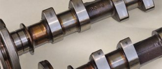
Marks in the timing system on a Niva Chevrolet car are special types of notches and holes that are located on the gas distributor pulleys. The photo shows pulleys with marks along which the timing chain is aligned.
Marks on the crankshaft pulley
Aligning the chain with marks is done so that it is better fixed and holds the gas distribution mechanism itself. If you install the chain without following the marks, then the operation of the pulleys will be uncoordinated and subsequently lead to their rapid wear
Therefore, it is important each time when replacing a chain or parts of the gas distribution mechanism, install them in accordance with the marks. It is possible that the timing system may malfunction when the chain tension is loosened or it is stretched.
In order to correctly set the timing mechanism according to special marks, we will consider the procedure for installing the gas distributor phases on the VAZ-2123.
Setting the timing of the gas distribution mechanism using special marks
So, setting the phases in the timing system according to special marks on a Niva Chevrolet car includes the following sequence of actions:
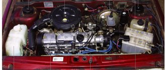
Initially, we make sure that we have the necessary tools: a screwdriver and wrenches “8”, “13” and “10”. You will also need a special tool to turn the crankshaft. The VAZ-2123 car is installed on the inspection hole and the wheels are secured using the handbrake. You can put shoes under the wheels. Open the hood on the Chevrolet Niva and remove the following elements: – remove the fan; – unscrew the radiator mounts and move it to the side
There is no need to remove the pipes and drain the liquid; – the air duct pipe is removed. Having reached the valve cover, you need to unscrew its fasteners and carefully remove it to prevent dirt and other objects from getting inside. After repair work, it is recommended to replace the cover gasket. After the cover was removed, the following view is observed, shown in the photo below.
Under the valve cover
The work carried out does not require much time, but is the key to the successful operation of the parts of the gas distribution mechanism of the Niva Chevrolet car
Drawing a conclusion, I would like to note the importance of setting the timing chain according to special marks. If for some reason you forgot to align the pulleys with the marks, then it is better not to start this process and make the adjustment again
This will extend the life of the timing system and all its components.
How is TDC determined?
By default, the TDC setting is made for the piston of the first cylinder . To do this, use marks on the engine body and marks on the crankshaft and camshaft pulleys. There are also TDC marks on the flywheel, and in a diesel engine, often on the fuel injection pump. If the marks do not match, then you need to carefully turn the crankshaft clockwise with a key.
Mark for setting TDC on the flywheel
Mark for TDC on the camshaft pulley
Engine Z14XEP
19. Checking and adjusting the valve timing is a very labor-intensive operation and can only be performed using special tools from Opel KM-952, KM-953 and KM-954.
Examination
20. Remove the air cleaner ().
21. Remove the ignition module ()
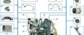
22. Disconnect the sensors and electrical supply wiring (see accompanying illustration) from the cylinder head cover.
6.22 Disconnecting sensors from the cylinder head cover (Z14XEP engine)
1 Camshaft sensor 2 Air flow control sensor 3 Engine oil pressure sensor 4 Coolant temperature sensor 5 Electrical wiring box
23. Disconnect the 2 crankcase ventilation system hoses.
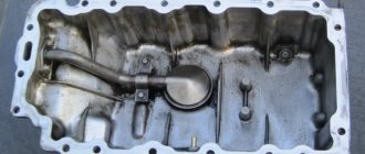
24. Remove the 13 mounting bolts and remove the cylinder head cover, remove the remains of the old cover gasket and clean the mating surfaces.
25. Remove the right engine boot ().
26. Remove the bolt that closes the crankshaft adjustment hole (see accompanying illustration) and lower the car.
6.26 Setting TDC on the Z14XEP engine
1 Bolt of the crankshaft adjustment hole 2 Installed device KM-952 3 Mark on the timing cover 4 Mark on the crankshaft pulley
27. Install the KM-952 tool in the hole (see illustration 6.26), and slowly and smoothly rotate the crankshaft until the tool engages with the shaft (fixes the shaft) - the marks on the crankshaft pulley and on the timing cover should coincide , and the timing cams above the first cylinder (see accompanying illustration) should face in opposite directions from the middle of the engine - if this position is not observed, turn the crankshaft another 1 revolution.
28. Install the special device KM-953 into the grooves of the camshafts (from the flywheel side) (see accompanying illustration) - the protrusions of the device should fit into the grooves as deep as possible. If it is not possible to install the device, it is necessary to adjust the valve timing (see below).
29. Install the special tool KM-954 (see accompanying illustration) so that the protrusion of the tool fits into the recess of the camshaft sensor rotor. If the protrusion and recess do not match, adjust the valve timing (see below).
Adjustment
30. Unlike models with a timing belt drive, the valve timing on this engine can be adjusted without removing the drive cover and the chain itself.
31. Upon completion of the check, remove devices KM-953 and 954 from the engine.
Attention: Under no circumstances should control devices be used to hold the engine shafts from turning!
32. Remove the bolt, freeing the hole for installing the KM-955-1 device (see illustration 6.32a). Using an open-end wrench, press the intake camshaft in the direction indicated by the arrow and fix the chain tensioner with the KM-955-1 device, thereby releasing the chain tension.
Attention: When pressing/turning camshafts, the key must be installed only on the hexagon-shaped part of the shaft (see illustration 6.32b)!
33. While holding the camshafts from turning, loosen the mounting bolts of the sprockets of both shafts (see illustration 6.32b), and then unscrew them one by one and replace them with new ones. Tighten the bolts so that the intake camshaft sensor rotor (see illustration 6.29) can be rotated manually.
34. Install the KM-953 device, turning the camshafts using an open-end wrench, and remove the KM-955-1 device.
35. Install the KM-954 device so that the protrusion of the device coincides with the recess of the rotor (see illustration 6.29) - if necessary, tighten the rotor manually.
36. Screw the bolt of the hole for installing the KM-955-1 device into place and tighten with the required force. Tighten the camshaft sprocket mounting bolts to a maximum torque of 10 Nm, then remove all adjusting devices.
37. Tighten the sprocket mounting bolts with a force of 50 Nm and another 60° - if necessary, use the help of an assistant, then smoothly rotate the engine crankshaft 2 full turns and, using the tools, check the TDC position - if the tools are not installed (see above) , re-adjust the valve timing.
Installation
38. Installation of all removed components is carried out in the reverse order of removal. When assembling, use a new cylinder head cover gasket (see accompanying illustration), apply sealant (gray) to the joints of the cylinder head and timing cover.
Attention: The cover must be installed within 10 minutes after applying the sealant!
Don't forget to replace the adjuster bolt gasket.
What happens if the TDC is installed incorrectly
When the piston of the first cylinder is correctly positioned at TDC on the compression stroke, the valves of that cylinder are fully closed. At this time, the second and third cylinders are at BDC (bottom dead center) and their valves are fully open.
Therefore, if the TDC is set incorrectly, the valve timing will be disrupted and the engine will not operate properly. If the violation is severe, the car will not start. If the piston is installed with a slight deviation from TDC, the engine will operate unstable: its power decreases, knocking, vibration, increased fuel consumption, accelerated wear of the elements of the cylinder-piston group and poor response to the gas pedal appear.
TDC - Top Dead Center
Calculator for converting kilowatts to horsepower (kW to hp)
Converting horsepower to kilowatts (hp to kW).
Conversion on an online calculator Top dead center (aka TDC ) is the highest point at which the piston can be relative to the crankshaft axis. But since engines can have different designs and locations, the most correct definition would be that TDC is “the position of the piston in which any point of the piston is at the maximum distance from the axis of rotation of the crankshaft.”
While going through the working cycle, the piston hits TDC twice - at the end of the compression and exhaust strokes. By default, TDC is the piston position at the end of the compression stroke.
Piston duty cycle
The essence and role of valve timing
At the moment, there are engines in which the phases cannot be changed forcibly, and engines equipped with mechanisms for changing valve timing (for example, CVVT). For the first type of engine, the phases are selected experimentally during the design and calculation of the power unit.
Unregulated and variable valve timing
Visually, they are all displayed on special valve timing diagrams. Top and bottom dead centers (TDC and BDC, respectively) are the extreme positions of the piston moving in the cylinder, which correspond to the largest and smallest distance between an arbitrary point of the piston and the axis of rotation of the engine crankshaft. The starting points for valve opening and closing (phase length) are shown in degrees and are considered relative to the rotation of the crankshaft.
The phases are controlled using a gas distribution mechanism (GDM), which consists of the following elements:
- cam camshaft (one or two);
- valve mechanism;
- chain or belt drive from the crankshaft to the camshaft.
Gas distribution mechanism
The engine operating cycle always consists of strokes, each of which corresponds to a certain position of the valves at the inlet and outlet. Thus, the beginning and end of the phase depend on the angle of the crankshaft, which is connected to the camshaft, which controls the position of the valves.
For one revolution of the camshaft, the crankshaft makes two revolutions and its total angle of rotation during the operating cycle is 720°.
Circular valve timing diagram
Let's consider the operation of valve timing for a four-stroke engine using the following example (see picture):
- Inlet . At this stage, the piston moves from TDC to BDC, and the crankshaft rotates 180º. The exhaust valve is closed and the intake valve is subsequently opened. The latter occurs with an advance of 12º.
- Compression . The piston moves from BDC to TDC, and the crankshaft makes another rotation of 180º (360º from the initial position). The exhaust valve remains closed and the intake valve remains open until the crankshaft rotates 40º.
- Working progress . The piston moves from TDC to BDC under the influence of the ignition force of the air-fuel mixture. The intake valve is in the closed position, and the exhaust valve opens ahead of time when the crankshaft has not yet reached 42º BDC. At this stroke, the full rotation of the crankshaft is also 180º (540º from the initial position).
- Release . The piston moves from BDC to TDC and at the same time pushes out exhaust gases. At this moment, the intake valve is closed (it will open 12º before TDC), and the exhaust valve remains in the open position even after the crankshaft reaches TDC another 10º. The total amount of crankshaft rotation at this stroke is also 180º (720º from the starting point).
Timing timing also depends on the profile and position of the camshaft cams. So, if they are the same at the inlet and outlet, then the duration of opening of the valves will also be the same.
Labeling.
To set the Niva Chevrolet timing belt, you need to rotate the crankshaft until the marks on the camshaft gear and bearing are aligned. When the chain is positioned correctly, the marks on the crankshaft should align with the mark on the chain cover. For greater convenience, the notch has an oblong shape. If the notches do not match, it is necessary to adjust the position of the phases. To do this, you need to loosen the fastening of the lock washer, and then remove the bolt from the camshaft sprocket using a 13mm wrench. After this, the gearbox must be set to speed 1 so that the bolt securing the crankshaft gear does not turn
Then, together with the lock washer, the fastening bolt is unscrewed. It is important to remember that after carrying out these steps, the bolt is not fixed in anything, so it may fall into the engine sump. When carrying out work, it is necessary to use a wrench with a deep head. The next step is to remove the tensioner
If there is no need to replace this element, you can remove the chain by squeezing the plunger using a screwdriver. Then you need to slightly pull the chain towards you to remove it from the crankshaft sprocket. To adjust the chain and align it with the marks, it is necessary to move the chain by 1 tooth. To make work easier, it is better to install the sprocket together with the chain. In order for the holes in it and the alignment pin to coincide, you must turn the crankshaft in the desired direction to match the notches. After this, the lock washer is installed. The bolt is inserted into the fastening point, but is not tightened. For the next operation, the key for turning the crankshaft will again be useful. You should use it to make two or three turns to check that the marks match. If all marks match, the installation is considered complete. Otherwise, you must repeat all steps.
In fact, this work is completed in a fairly short time. The main thing to remember is that an exact match of the timing mark of the Niva Chevrolet guarantees correct and stable operation of the engine
It is also important to remember that when installing the valve cover, it is necessary to replace the gasket with a new one, because when removing the old one, microcracks may appear on the old one, through which oil will escape
Installing timing marks on a Niva Chevrolet
The Chevrolet Niva from the SUV family is equipped with a chain drive in the timing mechanism. The operational properties of a chain are much greater than those of a belt drive. The chain also has better technical characteristics, which affects the transmission torque. If a loose belt causes the pulley teeth to slip, a weakened chain does not allow this to happen. But with the operation of the car, the gas distribution chain also tends to wear out, stretch, burst and become unusable, which requires its replacement
At the stage of replacing the chain, it is important to carry out the installation following the marks. This article will tell you what tags are, their purpose and how to set them on a VAZ-2123.