02/16/2021 22,607 Moskvich
Author: Ivan Baranov
The owner of a classic model of the Russian automobile industry needs to know how to set the ignition on a Moskvich-412. This is a fairly elementary process, which nevertheless can create difficulties if you do not know the procedure. It is how the ignition is installed on the Moskvich 2140 and other models of the brand that will be discussed in this article.
[Hide]
Timing marks Moskvich 412
Its purpose is to ensure the timely entry of the combustible mixture into the engine cylinders and the release of exhaust gases, for which the engines are equipped with intake and exhaust valves, respectively, controlled by camshaft cams.
The valves of the gas distribution mechanism in engines can have a lower location, in which the valves are located in the cylinder block, and an upper location in the cylinder head. Modern passenger car engines use an overhead valve arrangement with the camshaft located in the cylinder block (MeMZ and GAZ-3102 engines) or in the cylinder head (Moskvich-412 and VAZ engines). This design allows for a compact combustion chamber, ensures better filling of the cylinders, reduces heat loss from the coolant and simplifies adjustment.
When the camshaft is located in the cylinder block of the GAZ-3102 car engine (see Fig. 7.), the camshaft cams 15, through pushers 14 placed in the guides of the block, and rods 13 act on the rocker arm 6, and the latter, with the opposite end, act on valve 5. When In the prechamber-flare ignition method, the gas distribution mechanism, in addition to the main ones, has an additional inlet valve 8, located in a separate housing.
Rice. 11. Gas distribution mechanism of the Moskvich-412 engine: 1— support washer, 2 — external valve spring, 3 — internal valve spring, 4 — cap, 5 — plate, 6 — sealing ring, 7 — crackers, 8 — tip of the adjusting screw , 9—rocker arm, 10—large spacer sleeve, 11—washer, 12—thrust flange, 13—driven sprocket, 14—small spacer sleeve, 15—rocker arm spring, 16—exhaust valve rocker arm axis, 17—camshaft, 18— setting pin, 19 — lock nut, 20 — adjusting screw, 21 — valve guide, 22 and 23 — exhaust and inlet valve seats, 24 and 25 — exhaust and inlet valves
When the camshaft is in the cylinder head, its cams act on the valves through special rocker arms (Fig. 11) or directly on the valve - the VAZ-2108 engine (Fig. 12). In such a gas distribution mechanism there are no pushers and rods, the design of the engine, the casting of the cylinder block are simplified, and the noise during engine operation is reduced.
Rice. 12. Gas distribution mechanism of the VAZ-2108 engine:
1 — cylinder head cover, 2 — camshaft cam, 3 — adjusting washer, 4 — pusher, 5 — valve oil seal, 6 — valve, 7 — spark plug; A - adjustment gap
The camshaft is driven into rotation by the crankshaft, and for two revolutions of the crankshaft, the camshaft makes one revolution. When the camshaft is placed in the cylinder block, the drive is carried out through gears, one of which, usually the camshaft gear, is textolite; when placing the camshaft in the cylinder head - by a toothed belt or chain drive.
In the VAZ-2105 and VAZ-2108 engines, the camshaft in the cylinder head is driven into rotation by a toothed belt (Fig. 13), connecting the drive pulley 4 of the crankshaft and the driven pulley 9 mounted on the camshaft. To ensure correct engine valve timing—the timing of valve opening and closing—the timing marks C and D of the crankshaft pulley and E and F of the camshaft must match and be oriented as shown in Fig. 13.
Rice. 13. Drive diagram of the valve timing mechanism of the VAZ-2105 engine:
1 - crankshaft pulley, 2 - fan belt, 3 - lower protective cover, 4 - crankshaft toothed pulley, 5 - middle protective cover, 6 - tension roller bracket mounting bolts, 7 - tension roller, 8 - upper protective cover, 9 — camshaft pulley, 10 — toothed belt, 11 — tension roller bracket, 12 — bracket spring, 13 — oil pump drive roller pulley
If the camshaft is correctly connected by a belt or chain to the crankshaft, then in the position where the piston of the first cylinder is in the crank position during the compression stroke. m.t. (both valves of the first cylinder are closed, and the t.m.t. mark on the crankshaft pulley is located opposite the alignment pin on the lower cover of the gas distribution mechanism drive), the mark on the camshaft flange should coincide with the tide-mark on the front camshaft support shaft
Rice. 14. Drive of the gas distribution mechanism of the Moskvich-412 engine:
A - mounting key, B - mounting pin; 1 - drive sprocket, 2 - chain, 3 - double-arm lever, 4 - plunger block, 5 - tension spring, 6 - plunger, 7 - plug, 8 - driven sprocket, 9 - locking plate, 10 - bolt, 11, 13 - axles, 12, 14 - spring rings, 15 - tension sprocket, 16 - chain stabilizer, 17 - stabilizer axis (pin)
The Moskvich-412 engine (Fig. 14) uses a chain drive for the gas distribution mechanism. The plastic damper 16 of the drive, mounted on the front end of the cylinder block, is designed to dampen vibrations of the drive chain branch. The tensioning device acting on the driven branch of the chain is mounted on the front end of the cylinder head and in the upper cover of the gas distribution mechanism drive. It consists of a tension sprocket 15, a double-arm lever 3 on an axis 11 with a locking device and a spring 5 for periodically tightening the chain with a given force.
Camshafts are cast from cast iron or steel and have three support journals each for the Moskvich-412 and MeMZ-968 engines, and five each for the engines of VAZ and GAZ cars.
Lada 2106 third car (problematic › Logbook › wiring diagram from the distributor
I connected according to the principle of numbering on the distributor cover and counting the cylinders from the front to the rear of the engine in order, I tried to connect from the numbering on the distributor cover according to the 1-3-4-2 scheme - the result is that the car does not start... the distributor cover is positioned 180 degrees differently than on others Lada! exhibited on the principle of look, remember, stick
It turned out that the car starts only in this arrangement of wires from the distributor, from distributor 4 goes to spark plug 1, from 3 on the distributor goes to spark plug 2, from 2 on the distributor goes to spark plug 3 and, accordingly, from 1 on the distributor goes to spark plug 4... it started!
troits, smokes and farts) but it goes... after 5 minutes of running everything returns to normal, two out of four have screws. the spark plugs are “smoky”, the oil turned black after 2 days of driving (black works well, but it means the whole engine is crap inside - you need to wash it and fill it with new one)
Source
Installation instructions
To work, you will need tools such as a set of keys and a test lamp.
Read
The procedure for setting the ignition of Moskvich-412 is as follows:
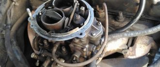
Distributor in a car
The procedure for setting the ignition of the Moskvich-412 is as follows:
In the video below you will learn how to set the cam clearance (the author of the video is Garage in the USSR).
How to set the ignition on a Moskvich 2140
How to set the ignition on a Moskvich using a light bulb. And some thoughts about the future.
In the video below you will learn how to set the cam clearance (author of the video Garage in the USSR).
Video “How to correctly set the ignition on a Moskvich 2140”
This video demonstrates how adjustments are made on one of the most popular Moskvich models (the author of the video is Maxim Mitin)
This video demonstrates how adjustments are made on one of the most popular Moskvich models (the author of the video is Maxim Mitin)
This video demonstrates how adjustments are made on one of the most popular Moskvich models (video author Maxim Mitin)
The ignition system of the VAZ 2107 consists of a high-voltage coil and a distributor - a contact interrupting mechanism. Incorrectly set ignition timing can cause a drop in power of the power unit or increased wear. Providing a spark in the engine piston before the end of the compression stroke is called pre-ignition and leads to premature ignition of the fuel-air fluid, which negatively affects the condition of the piston and connecting rod.
Retarded ignition is the appearance of a spark a few moments after the piston reaches top dead center. In most cases, the ignition is set a little late, but too much difference in timing leads to incomplete combustion of the fuel mixture, which causes carbon deposits and a lack of power.
Before setting up the ignition system, the car must be placed on a level surface, the gear must be in neutral and the parking brake must be engaged, or wheel chocks must be placed under the wheels. Having opened the hood body, it is necessary to remove dirt from the distributor cover and disconnect the negative terminal from the battery.
The distributor cover is mounted on spring clips, which can be unfastened with a thin screwdriver or an awl. After removing the cover, you need to clean the carbon electrode and the contacts of the slider from dust and carbon deposits, after which you can begin setting up. Regulation of the ignition system in car repair shops is carried out using a special strobe light.
At home, you can use an ordinary digital tester or an ohmmeter with pre-charging. Using a 38 key, you need to turn the engine crankshaft until the distributor slider approaches the first contact at an angle of up to 30 degrees. In this case, an ohmmeter connected to ground and the contact bolt of the distributor should indicate the presence of contact with zero resistance.
Next, rotate the shaft until the marks on the pulley and the distributor cover align. If, when combined, the ohmmeter shows a value tending to infinity, then the ignition is set correctly. Incorrectly set ignition timing can be diagnosed by the prolonged sound of detonation observed when engaging fourth gear at a speed of 50 km/h and sharply pressing the gas pedal.
When the ignition is set correctly, the ringing sound lasts no more than three seconds. A prolonged sound of detonation indicates an overestimated ignition angle, and its absence indicates an underestimated ignition angle. To adjust the ignition timing, you need to unscrew the bolt securing the distributor to the cylinder head. To reduce the ignition angle, the distributor body must be turned clockwise, and to increase it, counterclockwise. After setting up, you need to put the distributor cover back in place.
How to set the ignition on a Moskvich using a light bulb. And a few thoughts about the future. How to set the contact ignition on a Moskvich.
Setting up the Moskvich ignition. Part 1. Cam clearance. Setting the Moskvich ignition clearance.
Instructions: Removing and Installing the UZAM 412 cylinder head on a Moskvich 2140
Setting up the Moskvich ignition. Part 2. Moment.
Installation of BSZ on Moskvich 412 Non-contact ignition system on IZH-412.
Marks KV and RVstrange.
Ignition timing is the same. This is how everything is set up for me.
How to set the ignition on a Muscovite 412Ilya creative.
Installation of ignition by Bulb. Another way to set the ignition on your favorite car. For those who are new to our channel, we also...
Timing adjustment star M412 Timing adjustment star M412.
Moskvich 412 a little preparation after 8 years of hibernation Work done.
Repair of Moskvich 412 (Part 1). Installation of BSZ. Strange holes in the mixing chambers Ozone. Repair of Moskvich 412. Installation of BSZ, what and how (diagram). Strange holes in the carburetor mixing chambers...
Basic information about the contactless ignition system
The contactless ignition system is considered a continuation of the design of the transistor-contact system. The proximity sensor replaces the standard contact breaker of this system. Thanks to this system, it becomes possible to reduce fuel costs, increase engine power, reduce harmful emissions using a high discharge voltage of thirty thousand volts, as well as increase the quality of combustion of the air-fuel mixture.
The design of the contactless system of the Moskvich car is similar to the wired system, only the signal sensor and transistor switch are excluded and includes a whole list of various elements, which include:
Contactless ignition system for Moskvich
The main advantages of installing a BSZ on Moskvich are:
What is the operating principle?
A special sensor and distributor, when the engine crankshaft rotates, generates voltage signals, and then displays them on a transistor switch. The transistor switch generates signals in the initial winding circuit on the ignition coil. When the current in the secondary winding of the coil is interrupted, a high voltage current is generated and transmitted to the main contact of the distributor. Depending on the order of operation of the vehicle engine cylinders, high voltage current is transmitted to the spark plugs through high pressure wiring.
The spark plugs ignite the air-fuel mixture. As the engine crankshaft speed increases, the ignition timing is adjusted using a centrifugal ignition timing regulator.
When the load on the engine changes, the function of regulating the ignition timing switches to the vacuum ignition timing regulator.
Self-installation of a contactless ignition system
We will install the BSZ on Moskvich step by step, following the following algorithm:
Regulation of the contactless system
Please note that not only normal engine starting, but also fuel costs, vehicle dynamics and the service life of the entire vehicle as a whole depend on the ignition. That is why it is very important to correctly adjust the ignition system. Before using this control algorithm on cars of other brands, it is best to refer to the instructions for using your particular car. You will find the exact regulation value in the instructions for using your particular model. The regulation process is carried out in several stages:
Notes to note:
Error-free and quick do-it-yourself ignition installation on a Moskvich
The owner of a classic model of the Russian automobile industry needs to know how to set the ignition on a Moskvich-412. This is a fairly elementary process, which nevertheless can create difficulties if you do not know the procedure. It is how the ignition is installed on the Moskvich 2140 and other models of the brand that will be discussed in this article.
Tumblr installation and repair
The tumbler, also known as the ignition drive, may have various malfunctions: cracks in the cover, dirty or wet contact, or broken contact in the power circuit. You can solve them all or just replace the part.
To connect a new part, you will need to check that the roller is installed correctly in the housing. Then, after removing the tumbler cover, insert the shank into the distributor drive housing on the engine. Turn it until the floating clutch pins align.
Next, tighten the nut securing the distributor shank to the drive housing. Install the cover. Then, insert the high-voltage wires from the spark plugs in cylinder firing order 1-3-4-2, taking into account the rotation of the distributor rotor.
The tip of the high-voltage wire from the spark plug of the first cylinder is installed in the terminal socket above the low-voltage terminal in the housing. Next, the wire coming from the ignition coil is inserted into the central socket of the cover. All that remains is to connect the wire coming from the same one on the coil to the low-voltage terminal.
Now connect the vacuum regulator tube. Installation completed.
Ignition switch connection diagram
To install a new ZZ, your action plan should be as follows:
1. Dismantled device 2. Lock in the process of replacement 3. Lock diagram
Ignition system. The P118 type chopper-distributor is equipped with centrifugal and vacuum ignition timing regulators and an octane corrector. The distributor shaft is driven from a common drive mechanism with the engine oil pump.
The breaker opens the circuit of the primary winding of the ignition coil. Its main parts (Fig. 61) are a cam 17, placed on the upper part of the breaker-distributor roller, and a disk 12, on which a stand 8 with a fixed contact and a lever 9 with a movable contact are mounted. The fixed contact is connected to ground, and the lever with the moving contact is isolated from it and connected by a flexible wire 3 to terminal 14, connected by a wire to the terminal of the primary winding of the ignition coil. The normal gap between completely open breaker contacts is 0.35-0.45 mm. The gap is adjusted by rotating the eccentric 15 with the screw 4 securing the fixed contact post loosened. A capacitor 13 is attached to the body of the breaker-distributor externally, the capacitor wire is connected to terminal 14.
The distributor is used to distribute high-voltage current pulses that occur in the circuit of the secondary winding of the ignition coil when the circuit breaker breaks the primary winding across the spark plugs in accordance with the operating order of the cylinders. It consists of a carbolite cover 20 with central and side contacts and a carbolite rotor 1 with a metal current-carrying plate. The distributor rotor is installed on the cam 17 of the breaker, and the cover is installed on the body of the breaker-distributor.
The centrifugal ignition timing regulator, connecting the cam and the breaker shaft, changes the moments at which spark discharges appear in the spark plugs depending on the speed of rotation of the engine crankshaft. When it increases, the weights 27 of the regulator diverge to the sides from the axis of rotation of the roller 24 and the regulator turns the cam relative to the roller in the direction of rotation, as a result of which the contacts break and, accordingly, the spark discharge in the spark plug occurs earlier. When the crankshaft rotation speed decreases, the regulator turns the cam against the direction of rotation and the contacts break later.
Vacuum ignition timing regulator 6 changes the timing of the breaker contacts depending on the engine load. When the driver closes the carburetor throttles, the vacuum behind the throttles, as well as in the regulator cavity connected to the carburetor, increases, the regulator diaphragm, arching, turns the breaker disk 12 in the direction opposite to the direction of rotation of the cam, and the cam protrusions break the contacts earlier. As the throttle opening increases, the vacuum behind the throttle and in the regulator cavity decreases, the diaphragm spring turns the disk in the direction of rotation of the cam and the cam protrusions later open the contacts.
The octane corrector allows you to clarify the moment of contact rupture and the appearance of a spark discharge in spark plugs, depending on the octane number of the fuel. It consists of 2 lower and 1 upper plates. The upper plate is rigidly attached to the body of the breaker-distributor with a bolt 25, and the lower plate is put on the front stud for fastening the drive housing of the breaker-distributor and the oil pump and, together with the drive body, is secured to this stud with a nut. The plates are connected to each other by a coupling bolt and nut. Thus, with the help of octane corrector plates, the body of the breaker-distributor is attached to the engine, but if necessary, it can be rotated relative to its roller in one direction or another, which allows you to change the moments of opening of the breaker contacts and the appearance of spark discharges in the spark plugs.