Brake system: UAZ “loaf” mechanics
UAZ 3741 or 452, called by the people “loaf”, is the most famous creation of the Ulyanovsk Automobile and is remembered as a reliable ambulance, emergency gas service, police, water utility vehicle.
She has many positive qualities. It is unpretentious in maintenance, has excellent maneuverability and endurance. But for all its advantages, like any machine, sooner or later it needs partial or major repairs. For this purpose, it is not necessary to contact service centers. The structure of a domestic car is not very complicated, and you can figure out how to repair some of its parts yourself.
Parking brake system of UAZ vehicles
Parking mechanism diagram
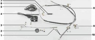
Rice. 2 Parking brake system: a – view with brake drum; b – view without brake drum; 1 – adjustment fork; 2 – lock nut; 3 – drive rod; 4 – expansion cracker; 5 – plug; 6 – drive lever; 7 – adjustment screw; 8 – block support; 9 – pusher of the expansion unit; 10 – ball body; 11 – housing of the expansion unit; 12 – brake drum; 13 – first block; 14 – tension spring of pads; 15 – cap; 16 – expansion unit ball; 17 – bolt; 18 – second block; 19 – brake shield; 20 – housing of the adjustment mechanism; 21 – rod; 22 – spring; 23 – spring cup.
Operating principle of the parking mechanism
The brake mechanism of the parking system is equipped on the transfer case and brakes the rear propeller shaft of the Bukhanka. Its design includes a support disk with two pads installed on it, connected by springs. The pads act on the brake drum, which is fixed on the centering belt of the propeller shaft flange. Attached to the top of the support disk is the housing of the expansion unit with pushers, which are attached to the top of the pads. Inside, the pushers are equipped with recesses filled with balls that are located in the rod. The housing of the adjusting element is installed at the bottom of the support disk. The recesses of the housing contain pad supports that can move due to the work of the block and the adjusting screw.
The brake mechanism drive includes a lever mounted on the support disk and an expansion element supporting the rod of the balls. The free end of the lever is attached to the fork, which in turn is attached to the rod using a lock nut. The drive rod is attached to the parking brake lever, which is installed in the driver’s cab.
In addition, on the UAZ Bukhanka, the parking brake system drive is supplemented with an extension located between the parking brake lever and the brake mechanism. This extension cord is a steel cable with elements for its fastening.
Read also:
— Tuning UAZ Bukhanka — making an exclusive out of a simple bus — Tuning UAZ Hunter — a whim or necessary modifications? — How to lift a UAZ “Loaf” — A trunk on a Niva with your own hands — A trailer on a UAZ with your own hands — Are tracks effective for a Niva?
comments powered by HyperComments
How to properly bleed the brakes
Having prepared everything you need, you can start bleeding the brakes. Correctly follow the following algorithm:
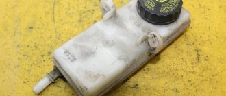
- Brake fluid is poured into the brake master cylinder reservoir so that it reaches the top of the reservoir;
- On all wheels, the air release valve is cleaned of dirt and dust to prevent debris from entering the system;
- Next, a little brake fluid is poured into the prepared container, and the hose is pulled onto the wheel air release valve, from which pumping begins. Don't forget to remove the cap from the valve first (don't lose it). The second end of the hose is immersed in brake fluid poured into a container;
When the pedal is depressed, you need to unscrew the air valve half a turn. At this point, it is important that the hose remains submerged in the brake fluid. When unscrewing, some of the excess air will pass through it, which will be marked by the appearance of bubbles on the surface of the brake fluid;
- After all the bubbles have come out, you need to screw the air valve back on and give the command to release the brake;
- Next, instructions points 4 to 6 must be repeated several times (usually about 5). This is necessary so that all the air is gone;
- Having completely bled the brakes of one wheel, you need to remove the hose, put the protective cap on the fitting and move on to the next wheels.
Important: During operation, brake fluid will leak from the master cylinder barrel. It must be monitored so that it does not fall below the minimum acceptable norm.
After performing the bleeding procedure, check the brake system before driving on busy roads or accelerating at high speeds. If the pedal remains soft, you need to diagnose the brake system, paying special attention to the wear of the pads and discs.
( 436 votes, average: 4.59 out of 5)
Related Posts
Plastic, metal, aluminum gas tank - which is better?
Oil gets into antifreeze: what is the reason and how to fix it
Bleeding brakes UAZ 469
The purpose of carrying out pumping manipulations is to remove the air contained in the internal parts of the braking mechanism. Periodically, once a week, inspect the machine for damage and leaks, paying attention to:
Braking mechanism UAZ (469, 452):
A sign that it is time to perform pumping manipulations is an increased working stroke of the foot brake lever, as well as detection of dips when pressing the foot brake. In addition, the lubricant is changed after repairs or replacement of components or parts of mechanisms. Regardless of the circumstances, you need to refill DOT-4 brake concentrate and bleed the brakes on UAZ 469 and 452 once every two years.
I can't bleed the brakes on a loaf
Messages: 2 Registered: 07 Aug 2014, 00:00
| Rating: 2 |
| Reputation: 0 |
I can't bleed the brakes on a loaf
Post by car driver » 07 Aug 2014, 21:33
Messages: 1082 Registered: June 16, 2010, 00:00 From: Tyumen Car: SUZUKI GRAND VITARA 2.5V6
| Rating: 1 882 |
| Reputation: 0 |
Thanked: 10 times Thanked: 16 times
Post by alfista » 07 Aug 2014, 21:36
Messages: 2 Registered: 07 Aug 2014, 00:00
| Rating: 2 |
| Reputation: 0 |
Post by car driver » 07 Aug 2014, 21:49
Messages: 1082 Registered: June 16, 2010, 00:00 From: Tyumen Car: SUZUKI GRAND VITARA 2.5V6
| Rating: 1 882 |
| Reputation: 0 |
Thanked: 10 times Thanked: 16 times
Post by alfista » 07 Aug 2014, 21:53
Messages: 1164 Joined: Oct 13, 2011 00:00
| Rating: 3 017 |
| Reputation: +4 |
Thanked: 47 times Thanked: 29 times
Post by mono1 » 07 Aug 2014, 21:54
Messages: 9649 Registered: Jan 21, 2008, 00:00 :
Awards: 1
| Rating: 55 325 |
| Reputation: +93 |
Thanked: 1428 times Thanked: 685 times
Post by USA » 07 Aug 2014, 21:56
Messages: 1571 Registered: Dec 29, 2011, 00:00 Experience: enough for me Car: won’t start
| Rating: 2 271 |
| Reputation: +3 |
Thanked: 51 times Thanked: 8 times
Post by Sanek_880 » 07 Aug 2014, 21:58
Messages: 1082 Registered: June 16, 2010, 00:00 From: Tyumen Car: SUZUKI GRAND VITARA 2.5V6
| Rating: 1 882 |
| Reputation: 0 |
Thanked: 10 times Thanked: 16 times
Post by alfista » 07 Aug 2014, 22:01
Messages: 2580 Registered: May 17, 2011, 00:00
| Rating: 5 952 |
| Reputation: +25 |
Thanked: 20 times Thanked: 15 times
Post by Salvador » 07 Aug 2014, 22:02
Messages: 1571 Registered: Dec 29, 2011, 00:00 Experience: enough for me Car: won’t start
| Rating: 2 271 |
| Reputation: +3 |
Thanked: 51 times Thanked: 8 times
Post by Sanek_880 » 07 Aug 2014, 22:15
Messages: 1164 Joined: Oct 13, 2011 00:00
| Rating: 3 017 |
| Reputation: +4 |
Thanked: 47 times Thanked: 29 times
Post by mono1 » 07 Aug 2014, 22:20
Messages: 525 Registered: Oct 18, 2011, 00:00 From: Tyumen Experience: 2000 Car: Mazda 6 III
| Rating: 3 545 |
| Reputation: +11 |
Thanked: 11 times Thanked: 38 times
Post by IVAN484 » 07 Aug 2014, 22:22
| Rating: 1 506 |
| Reputation: +3 |
Thanked: 8 times
Message 984490 » 07 Aug 2014, 23:08
Messages: 1926 Registered: Sep 13, 2010, 00:00 From: Tyumen Experience: since February 2002
| Rating: 7 716 |
| Reputation: +8 |
Thanked: 46 times Thanked: 55 times
Post by sniper81 » Aug 07, 2014, 11:29 pm
Plusan. there was a loaf done exactly like that.
I drive: UAZ 31514
| Rating: 7 346 |
| Reputation: +14 |
Thanked: 328 times Thanked: 82 times
Post by Grinding » 08 Aug 2014, 01:09
Replacing brake fluid
Not all car owners know that brake fluid needs to be replaced every two years when the car is used in moderate conditions. The main mistake is often that many people simply add lubricant to the required level, rather than change it completely.
UAZ loaf How to bleed the brakes alone
How to bleed your brakes alone
Before this, you need to unscrew the cylinder or caliper fitting a little so that the liquid flows out a little by gravity...
Every 60 thousand kilometers, the brake fluid needs to be replaced. Car brake fluid can withstand very serious loads. During intensive driving and sudden stops, the temperature range can vary from 170 to 2000°C. It needs to be completely changed because as it moves, water gets into the liquid and dilutes it. A lower concentration negatively affects the quality of the substance. If the liquid is too diluted and boils, it can block the brakes with steam and subsequently lead to an emergency.
Nowadays, car companies have developed a special device that determines the boiling point of brake fluid. The device diagnoses the substance and displays appropriate recommendations. It can show the condition of the fluid at the moment and how necessary it is to replace it as soon as possible. The entire procedure takes no more than a minute, but this frees car owners from unnecessary hassle.
Adjusting the brakes of the UAZ 3303. The quick method.
The article discusses adjusting the brakes of the UAZ 3303 (Adjusting the brakes on the UAZ Bukhanka is similar)
As I wrote earlier here, the brake pedal went to the floor. There were no leaks in the brake system, so most likely it was necessary to separate the brake pads.
It is known that during the operation of a UAZ, the brake pads wear out, so it is necessary to periodically remove them or, in technical terms, adjust them.
Let's look at the main stages of adjusting UAZ brake pads
- Theory of Brake Adjustment of UAZ 3303
- Detailed description of adjusting the rear brakes of the UAZ 3303 with photographs
- Detailed description of adjusting the front brakes of the UAZ 3303 with photographs
Theory of brake adjustment UAZ 3303
Here's what the instructions say:
In short, it’s written so ornately that without half a liter you can’t figure it out :-)
Detailed description of adjusting the front brakes of the UAZ 3303 with photographs
1) Place the car on a level area.
2) Do not tighten the handbrake, having previously installed the wheel chocks (for example, a chock floor :-))
3) jack up the rear wheel
4) Turn the bolt indicated by the arrow in the direction indicated by the dotted arrow, at the same time turn the wheel by hand until it slows down. When the wheel begins to slow down, slowly turn the bolt in the opposite direction until the wheel is released (in short, we are looking for the “limit” position). The photo shows the left rear wheel. The arrow marks the adjusting bolt of the rear wheel pad.
The adjusting bolt of the front brake pad of the rear wheel rotates in the opposite direction. (Not visible in the photo.)
Rear wheel diagram and rear wheel adjustment principle.
Detailed description of adjusting the front brakes of the UAZ 3303 with photographs
front adjustment bolts rotate in the direction of rotation of the wheel towards the front.
Front wheel diagram and front wheel adjustment principle.
I hope this article will help you adjust the UAZ brakes yourself. Don't forget to check the integrity of the brake hoses. And the reliability of the parking brake.
If the UAZ pulls to the side when braking, it means that the brake pads on the opposite side are weakly braking: that is, if the car turns to the right, then its left side does not brake and vice versa. Also, the car pulls to the side when the front wheels brake harder than the rear wheels, and as a result, a skid occurs (this can only appear in winter.).
In my case, adjusting the brakes helped, my UAZ 3303 began to brake adequately :-)
When adjusting the brakes, do not forget about safety precautions when working with a jack.
Bleeding the hydraulic brake system of UAZ Hunter 31516
- Repair manuals
- Repair manual for UAZ 31519 (Hunter) 2003.
- Bleeding the hydraulic brake system
The hydraulic brake drive is pumped to remove air that got in when it was filled with fluid after replacing it or after repairing hydraulic drive units associated with its depressurization.
Signs of air in the hydraulic drive:
– an increase in the pedal stroke, its “softness” when pressing the pedal once;
– a gradual decrease in the pedal stroke with a simultaneous increase in its “hardness” when the pedal is pressed repeatedly.
Before bleeding the hydraulic drive, it is necessary to identify and eliminate the cause of depressurization.
| Helpful advice If pumping a hydraulic drive is associated with the repair of one circuit and the serviceability of another circuit is known, then pumping only the circuit being repaired is permissible. |
The steps for bleeding the hydraulic drive are the same as when replacing brake fluid, described in Section. 4 “Maintenance” (see “Replacing the brake fluid” ). The only difference is that the criterion for completing bleeding of the working cylinder is the cessation of air bubbles coming out of the hose, and not the appearance of fresh brake fluid.
↓ Comments ↓
1. Car structure
1.0 Car structure 1.1 General information about the car 1.2 Passport data 1.3 Car keys 1.4 Instrument panel and controls 1.5 Heating and interior ventilation 1.6 Doors 1.7. Seats 1.8 Rear view mirrors 1.9 Interior lighting
2. Recommendations for use
2.0 Recommendations for use 2.1. Safety rules and recommendations 2.2 Recommendations for traffic safety 2.3. What you need to have in your car 2.4 Operating the car during the warranty period 2.5 Running in the car 2.6. Preparing the car for departure 2.7 Refueling the car 2.8 Using a jack 2.9 Towing the car
3. Problems along the way
3.0 Malfunctions along the way 3.1. The engine does not start 3.2 Malfunctions of the fuel injection system 3.3. Interruptions in engine operation 3.4. The car moves jerkily 3.5 The car accelerates poorly 3.6 The engine stalled while driving 3.7. Oil pressure dropped to 3.8. Engine overheating 3.9. The battery does not recharge 3.11. Extraneous knocking noises appeared 3.12. Problems with brakes 3.13. Wheel puncture
4. Maintenance
4.0 Maintenance 4.1. General provisions 4.2. Daily Maintenance (EO) 4.3. First maintenance (TO-1) 4.4. Second technical maintenance (TO-2) 4.5. Features of the first technical maintenance (TO-1) of cars with a diesel engine 4.6. Features of the second technical service (TO-2) for cars with a diesel engine
5. Engine
5.0 Engine 5.1 Design features 5.2 Possible engine malfunctions, their causes and solutions 5.3 Helpful tips 5.4 Checking compression in the cylinders 5.5 Removing and installing engine mudguards 5.6. Replacing the suspension supports of the power unit 5.7 Replacing the generator and water pump drive belt 5.8 Installing the piston of the first cylinder to the TDC position of the compression stroke 5.9 Replacing chains and gears of the gas distribution mechanism 5.13. Replacing engine seal parts 5.14. Engine cylinder head 5.16. Engine repair 5.17. Engine lubrication system 5.18. Engine cooling system 5.19. Exhaust system 5.20. Power system 5.21. Fuel vapor recovery system 5.22. Diesel engine design features
6. Transmission
6.0 Transmission 6.1. Clutch 6.2. Gearbox 6.3. Transfer case 6.4. Cardan transmission 6.5. Front axle 6.6. Rear axle
7. Chassis
7.0 Chassis 7.1. Front suspension 7.2. Rear suspension
8. Steering
8.0 Steering 8.1 Design features 8.2 Possible steering malfunctions, their causes and solutions 8.3. Steering column 8.4. Steering linkage 8.5. Steering gear
9. Brake system
9.0 Brake system 9.1 Design features 9.2 Possible malfunctions of the brake system, their causes and solutions 9.3 Bleeding the brake system hydraulic drive 9.4 Checking and adjusting the free play of the brake pedal 9.5. Main brake cylinder 9.6 Replacing the vacuum brake booster 9.7. Replacement of hoses and pipelines of the hydraulic brake drive 9.8. Front wheel brakes 9.9. Brake mechanisms of the rear wheels 9.10. Brake force regulator in the hydraulic drive of the rear brakes 9.11. Parking brake
10. Electrical equipment
10.0 Electrical equipment 10.1 Design features 10.2. Battery 10.3. Mounting blocks 10.4. Generator 10.5. Starter 10.6. Ignition switch (lock) 10.7. Electronic petrol engine control system (fuel injection system) 10.8. Ignition system of injection engines 10.9. Electronic diesel engine control system (fuel injection system) 10.10. Lighting, light and sound signaling 10.11. Windshield cleaner 10.12. Windshield washer reservoir 10.13. Tailgate glass cleaner 10.14. Tailgate glass washer reservoir 10.15. Electric motor of the heating and ventilation system fan 10.16. Cigarette lighter 10.17. Instrument cluster 10.18. Speedometer 10.19. Replacing sensors and switches
11. Body
11.0 Body 11.1 Design features 11.2. Removing and installing bumpers 11.3. Removing and installing wheel arch liners and mud flaps 11.4 Removing and installing front fenders 11.5 Removing and installing radiator trim 11.6 Removing and installing radiator trim 11.7 Removing and installing engine compartment mud flaps 11.8 Removing and installing floor hatch covers 11.9 Removing and installing the battery shelf 11.10. Hood 11.11. Side doors 11.12. Tailgate 11.14. Wind window 11.15. Hatch covers for filling pipes of fuel tanks 11.16. Seats 11.17. Mirrors 11.18. Interior fittings 11.19. Instrument panel 11.20. Heater 11.21. Body care
12. Tips for a novice auto mechanic
12.0 Tips for a novice auto mechanic 12.1. Safety precautions during repair work 12.2. Tools 12.3 Before you start 12.4. Restoring threaded connections 12.5 Tips for body repair
13. Purchase of spare parts
13.0 Purchasing spare parts 13.1 Engine oil 13.2 Greases 13.3 Coolants 13.4 Brake fluid 13.5 Fuel filter 13.6 Air filter 13.7 Engine lubrication system oil filter
14. A trip to the service station
14.0 A trip to the service station
15. Winter operation of the car
15.0 Winter operation of a car 15.1 How to prepare a car for winter 15.2 Recommendations for starting the engine in severe frost 15.3 What is useful to buy for winter 15.4 Useful winter tips
16. Preparation for technical inspection
16.0 Preparation for technical inspection 16.1 Recommendations 16.2 List of malfunctions and conditions under which the operation of vehicles is prohibited 16.3 Changes to state standards regulating the maximum permissible content of harmful substances in the exhaust gases of vehicles
17. Applications
17.0 Appendices 17.1 Appendix 1. Tightening torques for threaded connections 17.2 Appendix 2. Temperature range of application of motor oils 17.3 Appendix 3. Fuels and lubricants and operating fluids 17.4 Appendix 4. Lamps used on vehicles 17.5 Appendix 5. Special tools and accessories
18. Electrical diagrams
18.0 Electrical diagrams 18.1 Diagram 1. Connections of the engine control system mod. ZMZ-5143.10 18.2 Diagram 2. Connections of the engine control system mod. ZMZ-409 (Euro-2) 18.3 Diagram 3. Connections of the engine control system mod. ZMZ-409 (Euro-0) 18.4 Scheme 4. Electrical equipment of cars mod. 31519-095, 31519-195 18.5 Scheme 5. Electrical equipment of cars mod. 315195-025, 315195-125 18.6 Scheme 6. Electrical equipment of cars mod. 315195-023, 315195-123
UAZ-469 – brakes – Adjusting the service brake
Details Category: Control systems UAZ-469
Adjusting the service brake of UAZ-469
Perform routine brake adjustments in the following sequence: 1. Jack up the vehicle on the side of the wheel whose brake needs to be adjusted. 2. Rotate the wheel gradually and turn the adjusting eccentric until the wheel brakes. 3. Release the eccentric gradually, turning the wheel until it turns freely, without the drum touching the pads. 4. Adjust the gaps between the pads and drums of the remaining brakes in the same way. When adjusting the front brake pads (Fig. 98), as well as the front brake pads of the rear brakes (Fig. 99), rotate the wheel forward.
Rice. 98. Adjusting the gaps between the pads and the brake drum of the front wheel of the UAZ-469B car.
When adjusting the rear brake pads, rotate the wheel backwards. To reduce the gaps, turn the eccentrics in the direction of rotation of the wheel, and to increase them, on the contrary, against the rotation.
Rice. 99. Adjusting the gaps between the pads and the brake drum of the rear wheel of the UAZ-469B car
5. Check that the brake drums do not heat up and that the brakes operate evenly when braking while the vehicle is moving. During the current adjustment, do not use the support pins under any circumstances, as this will disrupt the factory settings of the pads. When replacing friction linings or pads, adjust the pads in the following sequence: 1. Raise the car with a jack on the side of the wheel whose brake you are adjusting. 2. Loosen the support pin nuts and set the support pins to the initial position (the marks on the ends of the support pins should be located as shown in Fig. 94, 95). 3. Pressing the brake pedal with a force of 12... 16 kgf-m, turn the support pins and move the ends of the shoes from the pin side until they stop against the drum (Fig. 100). Then tighten the support pin nuts in this position without allowing them to rotate. 4. Turn the adjusting eccentrics until they touch the brake pads. 5. Stop pressing the pedal and turn the adjusting eccentrics in the opposite direction until the wheels rotate freely. When installing new pads, when the friction linings have not yet been run in to the surface of the drums, the brake drums may heat up somewhat after the indicated adjustment. If the heating is small (the hand is comfortable when touching the drum rim), then after several braking the pads will break in and the heating will stop. When the brake drums become very hot, use the adjusting eccentrics to slightly move the heated brake pads away from the brake drum.
______________________________________________________________________________
______________________________________________________________________________
Brake system of UAZ-Hunter 315195, UAZ-31519 cars
On a UAZ-Hunter 315195, UAZ-31519 car, after a long period of parking (more than 8 hours), start driving no earlier than 20...30 seconds after starting the engine so that the vacuum pump creates a sufficient vacuum in the vacuum brake booster for comfortable braking. If you frequently press the brake pedal of a UAZ-Hunter, UAZ-31519 vehicle (after releasing the pedal, you immediately press it again), keep in mind that after the 2nd...3rd press, the force on the brake pedal may increase due to a decrease in vacuum in the vacuum booster . When you press the brake pedal (the car is stationary, the engine is idling), there may be a slight noise from the air intake into the vacuum booster.
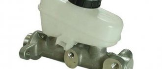
Fig.1. Main brake cylinder UAZ-Hunter 315195, UAZ-31519 1 - protective cap; 2 - cover with emergency brake fluid level sensor; 3 - tank; 4 - main brake cylinder housing; 5 - plug; 6.13-gaskets; 7 - plug insert; 8 - spring; 9 – spring seat; 10 - washers; 11,17-pistons; 12 - thrust bolt; 14 – sleeve-limiter; 15 - screw-stop; 16 — sealing collar; 18 — outer cuff; 19 - retaining ring; 20-connecting sleeve The level of brake fluid in reservoir 3 (Fig. 1) is checked visually using marks marked on the body of the reservoir, made of translucent plastic. With cover 2 removed and new brake linings UAZ-Hunter, UAZ-31519, the fluid level should be at the “MAX” mark. If the hydraulic brake drive is working properly, a decrease in the fluid level in the reservoir is associated with wear on the brake pad linings. A drop in the fluid level to the “MIN” mark indirectly indicates their maximum wear. In this case, it is necessary to directly monitor the condition of the linings, and there is no need to add liquid to the tank, because When installing new pads, the fluid level in the reservoir rises to normal. The emergency fluid level warning light in the tank lights up when the fluid level drops below the “MIN” mark, which, with partially worn or new brake pad linings, indicates a loss of tightness of the brake system of the UAZ-Hunter 315195, UAZ-31519 and a fluid leak. In this case, add fluid only after the system’s tightness has been restored. At the same time as checking the liquid level in the tank, check that the emergency level sensor is working properly by pressing on top of the central part of the protective cap 1 (when the ignition is turned on, the warning light on the instrument panel should light up). Check the condition of the brake hoses. If cracks appear on the outer surface, the hoses must be replaced.
Rice. 2. Front disc brakes UAZ-Hunter 315195, UAZ-31519 1 - spring; 2 - pads; 3 - bracket; 4 - caliper; 5 - protective cap; 6 - retaining ring; 7 - sealing ring; 8 - protective cover; 9 - piston; 10 - bushing; 11 - bolt; 12 -screw; 13 - plug; 14 – bypass valve; 15 - cap; 16 - spring holder mounting bolts; 17 – cylinder block; 18 - spring holder Disc brakes (brake mechanisms) of the front wheels of UAZ-Hunter 315195, UAZ-31519 To inspect brake pads 2 (Fig. 2), place the car on a horizontal platform, apply the parking brake and remove the wheel. Inspect the disc brake pads of UAZ-Hunter 315195, UAZ-31519 through the window in caliper 4. If the friction linings are worn to a thickness of 1.5-2.0 mm, then replace the pads with new ones. Replace on both front wheels. To replace the brake pads, unscrew bolts 16, remove holder 18 and spring 1. Check the condition of the brake disc. If there are deep scratches and nicks on the surface of the UAZ-Hunter, UAZ-31519 brake disc, then it must be removed from the vehicle, cleaned and sanded. If the disc wears down to a thickness of 20.4 mm, replace it with a new one. Check the protective caps 5 and covers 8, which must be undamaged and correctly installed in the sockets, and replace them if necessary. Check the presence of grease on the outer surface of the bushings 10 in the area of the covers 8 and, if necessary, lubricate with grease. Move the bracket 3 until the pistons 9 stop against the inner surface of the cylinder block 17. To facilitate the displacement of liquid from the cylinder block 17, the bypass valve 14 is allowed to open. Close the valve 14 as soon as the pistons 9 are completely recessed into the cylinder block. Before moving bracket 3, remove the cap of the master cylinder reservoir and do not allow fluid to overflow from it when moving the bracket. It is prohibited to use a mounting spatula to recess the pistons, as this will lead to deformation of the guide bushings 10 and failure of the bracket 3. Replace worn brake pads with new ones. Replace the brake pads of UAZ-Hunter 315195, UAZ-31519 vehicles as a complete set on both sides of the front axle. To bring the pads to the disc, press the brake pedal 2-3 times. Install spring 1, spring holder 18 and tighten bolts 16. During further operation, the required gap between the pads and the brake disc is maintained automatically.
Rice. 3. Rear wheel brake UAZ-Hunter 315195, UAZ-31519 a - marks on the support pins; b — wheel brake cylinder; 1 - support fingers; 2 - shield; 3 holes for visual inspection of the condition of the brake linings; 4-wheel brake cylinder; 5 - bypass valve; 6.12 - brake pads; 7 - protective cap; 8 - piston; 9 - sealing rings; 10 - thrust ring; 11 – tension spring; 13 - piston spring; 14-bolt adjusting eccentric; 15 - adjusting eccentric; Drum brakes (braking mechanisms) of the rear wheels and drum brake mechanisms of the front wheels of UAZ-Hunter 315195, UAZ-31519 Drum brake mechanisms of the front wheels of UAZ-Hunter, UAZ-31519 (Fig. 4) are installed on drive axles with a vertical crankcase connector. Periodically remove the brake drums and clean the brake parts from dust and dirt. The frequency of this operation depends on the operating conditions of the vehicle. In summer and when driving on dirty roads, cleaning should be carried out more often, in winter - less often.
Rice. 4. Front wheel brake UAZ-Hunter 315195, UAZ-31519 for axles with a vertical crankcase connector a - marks on the pins 1 - brake shield; 2 - rear connecting tube; 3-wheel cylinder; 4 - bypass valve; 5 - coupling; 6 - coupling spring of pads; 7 - pad lining; 8 - brake pad; 9 - protective cap; 10 - piston; 11 - sealing rings; 12 - piston spring; 13 - adjusting eccentric; 14 - support finger; 15 - nut; 16 - coupling bolt; 17 - gaskets; 18 - support sleeve; 19 - adjusting eccentric bolt; 20 - washer After removing the UAZ-Hunter, UAZ-31519 drum, check the reliability of fastening the wheel cylinders to the shields. Pay attention to the condition of the wheel cylinders, protective caps, the degree of wear of the friction linings, as well as the condition of the brake drum. In case of significant wear of the linings (the rivets are buried less than 0.5 mm), they must be replaced. When replacing worn pads or linings, the piston together with the thrust ring must be moved deep into the cylinder to freely slide the drum onto the pads. After assembly, you must press the brake pedal 2-3 times to set the pistons to the working position. Each time you remove the drum, clean the bead on the edge of the working surface that forms when the drum wears. With the hubs removed, tighten the bolts securing the brake shields. It is not recommended to move the brake drums of UAZ-Hunter, UAZ-31519 from one hub to another, as this leads to increased runout of the working surfaces of the drum. On UAZ-Hunter and UAZ-31519 vehicles equipped with drive axles with a vertical crankcase connector, it is necessary to periodically adjust the gaps between the pads and brake drums; the adjustment is carried out manually. The gap between the pads and the drum of the rear axle with a one-piece crankcase is restored automatically as the linings wear out. Adjust the gaps between the pads and brake drums of the UAZ-Hunter, UAZ-31519 in the following sequence: - Raise the car with a jack on the side of the wheel whose brake needs to be adjusted. — Rotate the wheel gradually and turn bolt 14 (see Fig. 3) or 19 (see Fig. 4) of the adjusting eccentric until the wheel brakes. — Release the eccentric gradually, turning the wheel until it rotates freely, without the drum hitting the pads. — Adjust the gaps between the pads and drums of the remaining brakes in the same way. When adjusting the front brake pads, as well as the front pads of the rear brakes of the UAZ-Hunter, UAZ-31519, rotate the wheel forward. When adjusting the rear brake pads, rotate the wheel backwards. To reduce the gaps, turn the eccentrics in the direction of rotation of the wheel, and to increase them, on the contrary, against the rotation. — Check that the brake drums do not heat up and that the brakes operate smoothly when braking while the vehicle is moving. During the current adjustment, do not use the support pins under any circumstances, as the factory setting of the pads will be disrupted. Brake system pressure regulator UAZ-Hunter 315195, UAZ-31519 When servicing, check the functionality of the brake system pressure regulator UAZ-Hunter, UAZ-31519 (Fig. 5). Clean the regulator from dirt and check the reliability of its fastening. By external inspection, make sure that the regulator and its drive parts are not damaged, there are no leaks of brake fluid and no play in the connection of the strut with the elastic lever and the bracket on the rear axle.
Rice. 5. Pressure regulator UAZ-Hunter 315195, UAZ-31519 1 - protective cover; 2 - retaining ring; 3 - bushing; 4 – piston sealing ring; 5, 7 - piston spring support washer; 6 – piston spring; 8 - seal; 9 - housing bushing; 10 - cuff; 11 - plug; 12 - plug gasket; 13 - bypass valve; 14 - cap; 15 - plug; 16 - body; 17 -piston When you press the brake pedal, the pressure regulator piston should move out of the housing by 1.7 - 2.3 mm. Lack of piston stroke, as well as insufficient or excessive stroke, indicates a malfunction of the regulator or its drive. When inspecting the hydraulic brake drive of the UAZ-Hunter, UAZ-31519, pay attention to the location of the control plug 15 (see Fig. 5) and the absence of brake fluid leaking from under it. In normal condition, the plug should be recessed into the hole in the regulator body until it stops.
If the plug protrudes from the hole and brake fluid leaks, the regulator must be repaired or replaced. During operation and when replacing rear springs, it is necessary to adjust the force of the elastic lever 5 (Fig. 6) on the regulator piston. Adjust the pressure regulator of the UAZ-Hunter, UAZ-31519 in the following sequence: - Place the equipped vehicle on a flat horizontal platform. — Loosen the locknut of the adjusting bolt 4 and unscrew the bolt 2-3 turns. — Screw in bolt 4 (see Fig. 6) until it comes into contact with the shank of piston 17 (see Fig. 5) of the regulator, tighten the bolt 1 turn (6 edges of the bolt head) and tighten the locknut. — Check the stroke of the regulator piston (see above). — Check that the adjustment is correct while the vehicle is moving. To do this, while driving along a straight horizontal section of the road with a dry asphalt surface, brake the car until the wheels lock. If the brake pressure regulator of the UAZ-Hunter, UAZ-31519 is in working order and the drive is adjusted correctly, there should be some advance in the locking of the front wheels relative to the rear ones. In case of advanced blocking of the rear wheels, additionally unscrew bolt 4 (see Fig. 6) on 1-2 edges of the bolt head and repeat the check while the vehicle is moving.
Rice. 6. Drive of the brake pressure regulator UAZ-Hunter 315195, UAZ-31519 1 - pressure regulator; 2 - bracket (base); 3 - drive lever; 4 - adjusting bolt; 5 - elastic lever; 6 - lever support For trouble-free operation of the brakes, replace the fluid regularly. Replace the fluid by draining the old fluid through the bypass valves of the wheel cylinders and the pressure regulator and replacing it with fresh one. Fill the brake system of the UAZ-Hunter, UAZ-31519 in the following sequence: - Check the tightness of all connections of the hydraulic drive of the brakes of the UAZ-Hunter 315195, UAZ-31519 and the condition of the flexible rubber hoses. — Clean the bypass valves and protective caps of the wheel cylinders and regulator from dust and dirt. — Clean the surface of the master cylinder reservoir around the cap from dust and unscrew the cap. Fill the reservoir with brake fluid to the MAX mark. — Press the brake pedal several times to eliminate the influence of the vacuum present in the vacuum brake booster. — Bleed the brake system. Bleed the brake system of UAZ-Hunter 315195, UAZ-31519 in the following sequence: - Alternately bleed the cavities of the right and left wheel cylinders of the rear brakes, the front circuit of the pressure regulator, the right and left wheel cylinders of the front brakes. — Remove the cap from the bypass valve of the UAZ-Hunter, UAZ-31519 wheel brake cylinder or pressure regulator and place a special rubber hose about 400 mm long on the valve. Lower the other end of this hose into a transparent container with a capacity of at least 0.5 liters, half filled with brake fluid. — Press the brake pedal sharply 3-5 times and, keeping the pedal pressed all the way, unscrew the bypass valve 1/2-3/4 of a turn, releasing a portion of the liquid from the system into the vessel. After the pedal goes forward all the way, tighten the valve. Repeat this operation until air bubbles stop emitting from the hose lowered into the container with brake fluid. — After pumping is complete, keep the pedal pressed all the way, tighten the valve and remove the hose. Wipe the valve head dry and put on the protective cap. — Add brake fluid to the master cylinder reservoir of UAZ-Hunter, UAZ-31519 to the MAX mark. Close the tank cap.
Tighten the cap with force to prevent its breakage. During the pumping process, add fluid to the master cylinder reservoir in a timely manner, not allowing the fluid level in the reservoir to decrease by more than 2/3 of its volume. Keep the end of the hose immersed in the liquid. Check the operation of the brakes while the vehicle is moving. With proper adjustment of the service brakes, their drive and correct bleeding of the brakes, full braking should occur within 1/2 - 2/3 of the pedal stroke. It is not recommended to add brake fluid to the master cylinder reservoir, which is collected in a container during bleeding.
Rice. 7. Drive of the main brake cylinder UAZ-Hunter 315195, UAZ-31519 1 - reservoir; 2 - main brake cylinder housing; 3 – vacuum booster; 4 - brake pedal; 5 - tension spring; 6 – brake signal switch; 7 - adjusting screw; 8, 9 - nuts; 10 -buffer Adjusting the free play of the brake pedal of UAZ-Hunter, UAZ-31519 cars On cars of environmental class 3, if necessary, by rotating the adjusting screw 7 (Fig. 7), select the gap in the connection: the vacuum booster pusher fork - the brake drive pin-lever. The pedal free play should be 5-14 mm. After adjustment, tighten nut 8 of the screw with a torque of 14 - 18 Nm (1.4 - 1.8 kg/cm). Adjust switch 6 using nuts 9, ensuring a gap of 0.5 mm, indicated in the figure. After adjustment, tighten the nuts to a torque of 4 - 6 Nm (0.4 - 0.6 kg/cm). On other vehicles, adjust the free play by setting the stop of the brake signal switch to a position that provides 5-14 mm of pedal free play. Parking brake system UAZ-Hunter 315195, UAZ-31519 Clean the brake pads of the UAZ-Hunter, UAZ-31519 from dust and dirt, and if the surfaces of the linings become tarred, clean them with sandpaper. Replace oily linings or soak them in clean gasoline for 20-30 minutes and clean them thoroughly with sandpaper or a wire brush. In case of significant wear of the linings (the rivets are buried less than 0.5 mm), they must be replaced. On new pads, grind the linings so that their diameter is 0.2-0.4 mm less than the diameter of the brake drum. Despite the sealing of the expansion and adjustment brake mechanisms of the UAZ-Hunter, UAZ-31519, dirt gradually accumulates in them, so periodically disassemble the mechanisms (especially the expansion mechanism), clean them of dirt and add fresh lubricant. In this case, lubricant should not get on the drum and friction linings.
Rice. 8. Parking brake mechanism drive for UAZ-Hunter 315195, UAZ-31519 vehicles with a five-speed gearbox 1 - drive lever with a sector; 2 - finger; 3, 13 - cotter pins; 4 - parking brake signal switch; 5 - nuts; 6 - washers; 7 - drive cable; 8 - bolts; 9 - spring washers; 10 - adjusting screw; 11 - tension spring; 12 – spring bracket; 14 - intermediate lever; 15 - drive rod; 16 - locknut; 17 - adjusting fork; 18 - drive lever; 19 – release mechanism ball housing Adjust the UAZ-Hunter, UAZ-31519 brake when the brake lever stroke becomes more than half of its maximum stroke and the braking efficiency becomes insufficient.
Rice. 9. Parking brake mechanism drive for UAZ-Hunter 315195, UAZ-31519 vehicles with a four-speed gearbox 1 - drive lever with a sector; 2 - finger; 3, 13 - cotter pins; 4 - parking brake signal switch; 5 - nuts; 6 - washers; 7 - drive cable; 8 - bolts; 9 - spring washers; 10 - adjusting screw; 11 - tension spring; 12 - spring bracket; 14 - intermediate lever; 15 - drive rod; 16 - locknut; 17 - adjusting fork; 18 – drive lever; 19 - housing of expansion mechanism balls Adjust the gaps between the brake pads and the drum of the UAZ-Hunter, UAZ-31519 in the following sequence: — Place the transfer case lever in the neutral position. — Move the parking brake lever 1 (Fig. 8, 9) to its lowest position. — Raise the car from the rear wheel with a jack. — Turn the adjusting screw 10 so that the brake drum does not turn by hand. — Unscrew the adjusting screw 4-6 clicks (1/3-1/2 turn) so that the drum rotates freely. Adjust the length of the brake drive rod of the UAZ-Hunter, UAZ-31519 in the following sequence: — Place lever 1 in the lowest position. — Tighten the adjusting screw 10 so that the brake drum does not turn by hand; — Unscrew the lock nut 16 of the adjusting fork 17, pin and remove the pin connecting the fork and the brake drive lever 18. — Rotating the fork 17, align the holes in the fork and lever 18. In this case, it is necessary to select the gaps in the release mechanism and the drive by moving the end of the lever 18 from hole and thrust 15 towards each other.
— Place the pin, pin it and tighten the locknut; - Unscrew the adjusting screw 10 by 4 - 6 clicks, the brake drum should rotate freely. If the parking brake is adjusted correctly, the car should brake when the lever pawl is installed in the 4th or 6th cavity of the sector, counting from the bottom (4-6 clicks). It is forbidden to check the operation of the parking brake when starting off or while driving. Check the operation of the parking brake only on a slope.
______________________________________________________________________________
______________________________________________________________________________
- Clutch and gearbox UAZ Hunter
- Transfer case and driveshafts UAZ Hunter
- Drive axles UAZ Hunter
- Adjusting the steering mechanism of the UAZ Hunter
______________________________________________________________________________
______________________________________________________________________________
- Checkpoint UAZ-Patriot
- Razdatka UAZ-Patriot
- Drive axles UAZ-Patriot
- UAZ-Patriot suspension
- Steering UAZ-Patriot
- UAZ Patriot power steering faults and their elimination
- Components of the UAZ-Patriot hydraulic brake drive
- UAZ-469 engine and its main parts
- Gearbox UAZ-469
- Drive front and rear axles of UAZ-469
- Clutch of UAZ-469 cars
______________________________________________________________________________
- Cylinder block and timing belt for UAZ-31512, 31514 engines
- Front and rear suspensions UAZ-31512, 31514
- Operations for assembly and disassembly of UAZ-31512, 31514 bridges
- Steering UAZ-31512, 31514 and its parts
- Brake system UAZ-31512, 31514
- Gearbox UAZ-452
- UAZ-452 clutch and its parts
- Transfer case UAZ-452
- UAZ-452 bridges and its components
- Gearbox UAZ-3909, UAZ-2206
- Cardan transmission UAZ-3909, UAZ-2206
- Front axle UAZ-3909, UAZ-2206
- Brakes UAZ-3909, UAZ-2206
- Clutch UAZ-3303
- Transfer case UAZ-3303
- Rear axle UAZ-3303
- Steering of UAZ-3303
- Cylinder block and crankshaft ZMZ-409
- Timing belt and valves ZMZ-409
- Lubrication system ZMZ-409
- Cooling and power system ZMZ-409
- Parts of the UMZ-421, UMZ-4218 cylinder block
- Timing belt and valves UMZ-421, UMZ-4218
- Lubrication system UMZ-421, UMZ-4218
- Cooling system UMZ-421, UMZ-4218
- Fuel system UMZ-421, UMZ-4218
Symptoms of a faulty master cylinder
It is super convenient to bleed the rear brakes by removing both wheels and placing the axle on two jacks parallel to the “horizon”. As a result, we avoid “get under the car - get out from under the car.” Without the 35th wheel removed, I was unable to get to the bypass valve.
The front brakes have separate wheel cylinders for each pad. Both brake pads are the same.
If the liquid is too diluted and boils, it can block the brakes with steam and subsequently lead to an emergency.
Brake system UAZ
- 1 Reasons
- 2 Tool
- 3 How to bleed the brakes on a UAZ alone
Of course, if only one working cylinder was repaired, there is no point in bleeding the entire system. If the gas turbine engine has been replaced, then full maintenance is necessary.
Tool
To carry out the work you must have:
- brake fluid, usually DOT4 or the one that is poured into the system;
- a clean container for collecting fuel fluid;
- hose for draining fluid from brake cylinders;
- key 10, unscrew the bypass valve.
Inside, the pushers are equipped with recesses filled with balls that are located in the rod. The housing of the adjusting element is installed at the bottom of the support disk. The recesses of the housing contain pad supports that can move due to the work of the block and the adjusting screw.
Unscrew the bypass valve ½ - ¾ of a turn, then press the pedal several times. Press the pedal quickly, release slowly.
It was decided not to change it, but to purchase a repair kit for the main brake cylinder and repair it ourselves. After two days of operation, the cylinder literally jammed. After disassembling it turned out that the rubber bands were swollen. The same thing happened with the second repair kit. The third one lasted a week, but still refused, since the rubber bands had simply worn out.
Bleeding the service brakes is done to remove air from the sealed hydraulic drive of the service brake system. It may be needed in the event of an increase in the working stroke or the appearance of softness in the brake pedal, changes for the worse in the operation of the braking system, for example, after repair or replacement of its individual components.
Brake fluids made from petroleum products may only be used in hydraulic drives whose seals and hoses are made of oil-resistant rubber. This is done in order to prevent the destruction of rubber parts.
In the middle part of the brake shields of the front and rear wheels there are eccentrics for adjusting the position of the pads after replacing them or during operation. In addition, when replacing pads, their position can be changed by turning the eccentric support pins. The pads are connected to the pads with aluminum rivets. Bleeding the service brakes is done to remove air from the sealed hydraulic drive of the service brake system.
Causes
The need to pump may arise for several reasons:
- air has entered the brake system;
- the main brake cylinder (GTC) has been replaced or repaired;
- replacement or repair of working brake cylinders;
- repair of the brake system (pipes, hoses);
- the pedal falls through without any visible fault;
- fluid change.
Of course, if only one working cylinder was repaired, there is no point in bleeding the entire system. If the gas turbine engine has been replaced, then full maintenance is necessary.
Tool
To carry out the work you must have:
- brake fluid, usually DOT4 or the one that is poured into the system;
- a clean container for collecting fuel fluid;
- hose for draining fluid from brake cylinders;
- key 10, unscrew the bypass valve.
The hose or tube must be such that it fits tightly onto the bypass valve and has a length of 40 centimeters.
Bleeding the brakes of the rear right wheel of the UAZ