Engine model
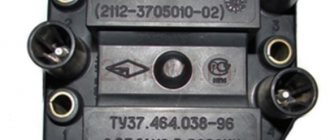
The most powerful engine of all that was installed on the “ten” is the injection 16-valve VAZ-2112 with a volume of 1.5 liters. However, this power unit has one drawback: if the timing belt breaks, the pistons meet the valves, which leads to serious and expensive repairs of the power unit. And high-quality repair and maintenance of VAZ-2110 injection engines requires special diagnostic equipment. Often, a malfunction of just one sensor leads to unstable operation of the entire engine.
Repair manual for VAZ 2110, 2112, 2111 (Lada 110)
1.1.
Overall dimensions of the VAZ-2110 car 1.2. Overall dimensions of the VAZ-2111 car
1.3. Overall dimensions of the VAZ-2112 car
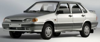
Small class cars VAZ-2110 (export name Lada 110) with a four-door five-seater sedan body (class C according to the international classification) are equipped with engines of 1.5 and 1.6 liters, with a power of 58–68 kW (79–92.5 hp). c.), located across the engine compartment.
Previously, cars at the factory were equipped with 1.5 liter engines: first with carburetor engines, and then with a distributed fuel injection system. Currently, cars are equipped only with engines with a displacement of 1.6 liters: eight-valve VAZ-21114 and sixteen-valve VAZ-21124 with distributed fuel injection systems and three-component exhaust gas catalysts with feedback. The engines meet Euro-2 and Euro-3 standards.
The body is load-bearing, all-metal, of welded construction with hinged doors, front fenders, hood and trunk lid. The VAZ-2110 car is the first sedan in Russia with a hatch that can be opened from the trunk leading into the cabin, which allows you to transport long items.
Part of the production modification 21103 with a 16-valve VAZ-2112 engine is equipped with air conditioning, and since the end of 2002, on request, power steering from ZF.
This modification differs from the basic one by a hood with an integrated radiator lining of a more modern shape and a front bumper, as well as original headlights. The rear lights, moldings and interior details have also been changed.
In 1998, production of the VAZ-2111 car (export name Lada 111) with a station wagon body began. According to the layout, engine, transmission, chassis, body equipment, this car is identical to the VAZ-2110 car. It features a redesigned rear end with a large tailgate. The trunk of this car is the most spacious in the family: 490 liters with the rear row of seats raised and 1420 liters with them folded.
Production of the VAZ-2112 car (export name Lada 112) with a hatchback body began in 2000. The layout of this car is the same as that of the VAZ-2111, but the body has a large rear angle. The engines are used only with a distributed injection system, both 8-valve and 16-valve. The rear seat folds in a 2:3 ratio, which increases trunk capacity from 415 to 1270 liters. The interior, like other models of the family, is equipped in “standard”, “norm” and “luxury” trim levels. The latest equipment includes fog lights, headlight cleaner and washer, 14-inch alloy wheels, three-way catalytic converter (Euro 2), internal bonnet lining, door security bars, immobilizer, on-board monitoring system, velvet seat upholstery and soft upholstery doors, central electric door locking, electric windows. By additional order, an on-board computer, electric front seat heaters, electric outside rear-view mirrors, anti-lock brakes, an airbag and a sunroof are installed.
1.4. Layout diagram of the VAZ-2111 car: 1 – engine; 2 – spare wheel; 3 – muffler; 4 – rear suspension strut; 5 – drum brake; 6 – rear suspension beam; 7 – fuel tank; 8 – resonator; 9 – disc brake; 10 – shock absorber strut; 11 – steering mechanism
The layout diagram of all three cars is almost the same, so it is shown using the example of a VAZ-2111 car in Fig. 1.4.
1.5. Engine compartment of cars with engine mod. 2111 (top view): 1 – engine; 2 – adsorber for the gasoline vapor recovery system; 3 – receiver; 4 – brake master cylinder; 5 – expansion tank; 6 – washer reservoir; 7 – battery; 8 – air filter; 9 – ignition module
1.6. The engine compartment of all cars is from below (engine protection removed): 1 – engine; 2 – starter; 3 – front suspension cross member; 4 – gearbox; 5 – stretching; 6 – exhaust pipe; 7 – anti-roll bar; 8 – front suspension arm; 9 – wheel drive; 10 – engine oil sump; 11 – generator
1.7. Engine compartment of cars with engine mod. 21124 (top view with the decorative cover removed): 1 – intake manifold with receiver; 2 – throttle unit; 3 – reservoir of the main brake cylinder; 4 – expansion tank; 5 – washer reservoir; 6 – inlet pipe; 7 – battery; 8 – air filter; 9 – ignition coil; 10 – timing belt protective cover; 11 – adsorber; 12 – tailgate glass washer reservoir (on cars with station wagon and hatchback bodies)
1.8. Engine compartment of cars with engine mod. 2112 (top view): 1 – engine; 2 – adsorber for the gasoline vapor recovery system; 3 – receiver; 4 – brake master cylinder; 5 – expansion tank; 6 – washer reservoir; 7 – battery
1.9. Controls: 1 – front door glass blower nozzle; 2 – side nozzles of the interior ventilation and heating system; 3 – glove box cover; 4 – clock (electronic or quartz); 5 – display unit of the on-board control system; 6 – radio socket cover; 7 – cigarette lighter; 8 – front ashtray; 9 – lining of the floor tunnel; 10 – control units*; 11 – parking brake lever; 12 – gear shift lever; 13 – accelerator pedal; 14 – socket for connecting a portable lamp; 15 – brake pedal; 16 – clutch pedal; 17 – ignition switch; 18 – steering column adjustment handle; 19 – hood lock drive handle; 20 – sound signal switch; 21 – mounting block cover; 22 – trunk (tailgate) lock drive switch*; 23 – mounting block lock button; 24 – headlight hydraulic corrector; 25 – lever for switching direction indicators and headlights; 26 – external lighting switch; 27 – front fog lamp switch*; 28 – control lamp for turning on fog lights*; 29 – instrument cluster; 30 – indicator lamp for turning on the rear fog light; 31 – rear fog light switch; 32 – control lamp for heated rear window; 33 – rear window heating switch; 34 – instrument lighting switch; 35 – immobilizer warning sensor*; 36 – switch lever for windshield wipers and washers; 37 – central nozzles of the interior ventilation and heating system; 38 – recirculation switch; 39 – air conditioner switch*; 40 – control lever for heating system dampers; 41 – controller of the automatic heating control system; 42 – alarm switch; 43 – switch for headlight cleaners and washers*; 44 – windshield blower nozzle
Description of the engine compartment of VAZ cars of the tenth family
All descriptions are presented in the form of drawings, from which the main components and parts of the VAZ 2110
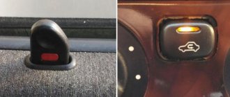
.
Rice. 1.4. Engine compartment
of cars with engine mod. 2111 (top view): 1 - engine; 2 — adsorber of the gasoline vapor recovery system; 3- receiver; 4- brake master cylinder; 5- expansion tank; 6 — washer reservoir; 7 - battery; 8- air filter; 9-ignition module
Rice. 1.5. The engine compartment of all cars is from below (engine protection removed): 1 - engine; 2 - starter; 3 — cross member of the front suspension; 4 — gearbox; 5 - stretching; 6 — exhaust pipe; 7 — anti-roll bar; 8 — front suspension arm; 9 — wheel drive; 10 — engine oil sump; 11 — generator Fig. 1.6. Engine compartment of cars with engine mod. 21124 (top view with the decorative cover removed): 1 - intake manifold with receiver; 2 — throttle assembly; 3 — brake master cylinder reservoir; 4 - expansion tank; 5 — washer reservoir; 6 — inlet pipe; 7 - battery; 8 — air filter; 9 — ignition coils; 10 — timing belt protective cover; 11 - adsorber; 12 — tailgate glass washer reservoir (on cars with station wagon and hatchback bodies) Fig. 1.7. Engine compartment of cars with engine mod. 2112 (top view): 1 - engine; 2 — adsorber of the gasoline vapor recovery system; 3 - receiver; 4 — brake master cylinder; 5 - expansion tank; 6 — washer reservoir; 7 - battery Fig. 1.8. Engine compartment of cars with engine mod. 21083-80 or 2110 (top view): 1 - engine; 2 — air filter: 3 — fuel pump; 4 — brake master cylinder; 5 - expansion tank; 6 — washer reservoir; 7 - battery; 8 — ignition distributor
If you liked it?! Share with a friend or girlfriend or a plus from the heart. Thank you so much, friends. (Social networks connected in August 2013)
Your reviews, comments, questions and answers on LADA-10.ru
Everyone is welcome to participate in the discussion about the causes of the malfunction and other problems. If you know what to answer, write and thereby help other VAZ 2110 owners in searching for the truth.
Comments on the LADA-10.ru website were launched on January 11, 2012
Source
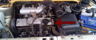
Tuning the engine compartment. Engine lighting
In continuation of the materials on tuning, we would like to present an unusual option for decorating the engine compartment of your car.
The source of illumination for the engine elements in this case is LEDs and LED strips. And so let’s imagine, it’s getting dark outside, you approach the car and open the hood, the hot-looking engine shocks the people around you. This effect is created using red LED sources. Beautiful. And at the same time it looks impressive.
In the example presented, the LEDs were installed under the motor protective casing.
The result of such tuning will look impressive on cars that have a protective casing. In the presented example you can see how this was done on a VAZ 2110 engine.
For illumination, an LED strip was used, the length of which is 85 cm. It was also secured to iron corners in the radiator area
When connecting the LED backlight, you should pay attention that all the wiring that you used must be insulated and corrugated. The power source must be connected through a fuse (for convenience, use a plug-in fuse) Also make sure that all wiring is at a certain distance from very hot engine elements
VAZ-2112 diagram
The VAZ-2112 car was produced at AvtoVAZ from 1998 to 2009, in Ukraine from 2009 to 2014. The following are color wiring diagrams (injector and carburetor) with a description of all elements for various modifications. The information is intended for self-repair of cars. Electrical circuits are divided into several blocks for ease of viewing via a computer or smartphone; there are also circuits in the form of a single picture with a description of the elements - for printing on a printer in one sheet.
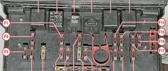
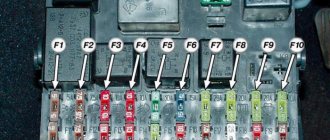
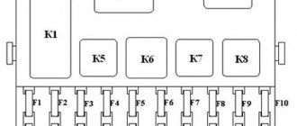
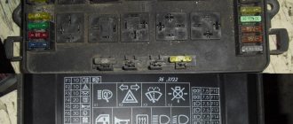
To diagnose and repair yourself, first look to see if everything is okay with the generator. Is it put on well and does not sag? This procedure must be done with all versions of the fuel system, both carburetor and injection. We check the fuses according to the electrical diagram. The reverse side of the safety block cover will also be of great help. There are clues there that the diagram will help you decipher. Replace the burnt out element and try to start the car again. You need to check whether the battery terminals are tightly connected and whether they are oxidized. Is the wire going from the battery to the generator and to the starter damaged?
Installation of fog lights
Car owners can independently equip their car with fog lights. To make installation easier, you can watch videos from forums where craftsmen share their experience of such work.
Conclusions: in fact, replacing old wiring in the rear of a car is much easier than in the engine compartment or inside the cabin. And the diagrams proposed in the article will help you figure it out faster and avoid mistakes.
Source
Modifications of the VAZ-2112 car
VAZ-21120 . Modification with a 16-valve injection engine with a volume of 1.5 liters and a power of 93 horsepower. 14-inch wheels were installed on the car. This modification has a problem with valves bending when the timing belt breaks. The problem can be solved by increasing the depth of the grooves in the piston bottoms.
VAZ-21121 . The car was equipped with a VAZ-21114 8-valve injection engine with a volume of 1.6 liters and a power of 81 horsepower.
VAZ-21122 . Budget modification with an 8-valve injection engine VAZ-2111. The car was produced without electric windows, the wheels were 13 inches in size, and the brakes were unventilated from a VAZ-2108 car.
VAZ-21123 Coupe . Three-door, five-seater hatchback. The only two doors for entering the car are 200 millimeters wider than those of the five-door hatchback, and they are mounted on new, durable hinges. The rear arches of the car have become wider. The engine was installed with a 16-valve injection engine with a volume of 1.6 liters and a power of 90 horsepower. The car was produced from 2002 to 2006 in small quantities, the reason for this was the high cost of the car.
VAZ-21124 . Modification with a 16-valve injection engine VAZ-21124 with a volume of 1.6 liters. Produced from 2004 to 2008. For this type of engine, the problem with valve bending was solved. To do this, the depth of the grooves in the piston heads was increased (up to 6.5 mm). In addition, the design of the cylinder block was changed to achieve a working volume of 1.6 liters, for which its height was increased by 2.3 mm, and the radius of the crankshaft was increased by 2.3 mm accordingly. There were also a number of other minor changes.
VAZ-21128 . The luxury version of the car, produced by Super-auto JSC, was equipped with a 16-valve VAZ-21128 engine with a volume of 1.8 liters and a power of 105 horsepower.
VAZ-2112-37 . A racing modification of the VAZ-2112, prepared for the “ring” in the Lada Cup qualifying group. The car was equipped with a 1.5-liter VAZ-2112 engine with a power of 100 horsepower. The racing car was equipped with a safety cage, an external aerodynamic kit and a front extension of the strut support cups.
VAZ-2112-90 Tarzan . All-wheel drive modification with a VAZ-2112 body on a frame chassis with transmission and suspension parts from a VAZ-21213 Niva. It was also equipped with a 1.7 or 1.8 liter engine from the Niva.
Where is the engine number 1 5: 16 valve injector
The cylinder head became two-shaft and increased in size. It was covered with a casing on top. It has become even more difficult to find the number of the 16 cl motor, but it is located in the same place - at the rear end of the block, above the flywheel. This hasn't changed.
Leaving fuel consumption at the same level, the 16-valve engine significantly increased its dynamics, increased power and traction.
Characteristics:
- Power - 93 hp;
- Torque - 128;
- Acceleration - 12.5;
- Maximum speed - 180;
- Consumption – 7.2 l.
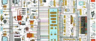
Electrical diagram of VAZ-2112
Designations: 1 – Headlight, 2 – Klaxon, 3 – Main radiator fan, 4 – Starter, 5 – Battery, 6 – Generator 2112, 7 – Gearbox limit switch (reverse), 8 – Actuator in the front passenger door, 9 – Power window enable relay, 10 – Starter relay, 11 – Heater fan, 12 – Electric heater partition drive, 13 – Main pump, 14 – Washer reservoir sensor, 15 – Driver’s door actuator, 16 – Front passenger window selector, 17 – Unlock button fifth door, 18 – Heater fan resistance unit, 19 – Main wiper motor, 20 – Driver’s window lift selector, 21 – Front passenger’s window lift motor, 22 – Central locking, 23 – Exterior light switch, 24 – Brake fluid leakage sensor, 25 – Pump additional, 26 – Driver's window lift motor, 27 – PTF on indicator, 28 – PTF switch, 29 – Dashboard, 30 – Heated glass on indicator, 31 – Heated glass switch, 32 – Steering column selector switch, 33 – PTF relay, 34 – Ignition switch, 35 – Main fuse block, 36 – Illumination of heater controls, 37 – Hazard warning button, 38 – Heater control controller, 39 – Glove compartment lighting, 40 – Glove compartment lid end cap, 41 – Cigarette lighter, 42 – BSK – display unit, 43 – Ashtray illumination, 44 – 12V socket, 45 – Instrument lighting switch, 46 – Actuator in the right rear door, 47 – Right rear passenger window selector, 48 – Clock, 49 – Right rear passenger window motor, 50 – Brake limit switch (closed – pedal is pressed), 51 – Left rear passenger window motor, 52 – Left rear passenger window selector, 53 – Actuator in the left rear door, 54 – Turn signal, 55 – Handbrake limit switch (closed – handbrake on), 56 – Rear wiper motor , 57 – Navigator's lamp, 58 – Interior lamp, 59 – Temperature sensor in the heater, 60 – Limit switch for the open front door, 61 – Limit switch for the open rear door, 62 – Trunk light, 63 – Rear optics (on the body), 64 – Rear optics (on the fifth door), 65 – License plate illumination.
The letters indicate the terminals to which it is connected: A – Front speaker on the right, B – Radio, C – Injector harness, D – ESD diagnostic connector, D – Front left speaker, E – Diagnostic connector for the heater controller, G – Rear right speaker, W – Rear left speaker, I – BC connector, K – glass heater thread, L – fifth door actuator, M – Additional brake light.
Wiring diagram VAZ-2112 injector 16 valves - full view
VAZ-21124 engine control circuit
Connection diagram of the VAZ-21124 engine control system with distributed fuel injection to Euro-2 emission standards (controller M7.9.7): 1 - ignition coils; 2 — nozzles; 3 - controller; 4 - main relay; 5 - fuse connected to the main relay; 6 — cooling system electric fan relay; 7 - fuse connected to the cooling system electric fan relay; 8 - electric fuel pump relay; 9 - fuse connected to the electric fuel pump relay; 10 — mass flow and air temperature sensor; 11 — throttle position sensor; 12 — coolant temperature sensor; 13 — solenoid valve for purge of the adsorber; 14 — oxygen sensor; 15 — knock sensor; 16 — crankshaft position sensor; 17 — idle speed regulator; 18 — immobilizer control unit; 19 — immobilizer status indicator; 20 - phase sensor; 21 — vehicle speed sensor; 22 — electric fuel pump module with fuel level sensor; 23 — oil pressure warning lamp sensor; 24 — coolant temperature indicator sensor; A - block connected to the wiring harness of the ABS cabin group; B — diagnostic block; B - block connected to the air conditioner wiring harness; G - to the “+” terminal of the battery; D — to the side door wiring harness block; E - block connected to the instrument panel wiring harness; G1, G2 - grounding points; I - the order of conditional numbering of plugs in the block of the immobilizer control unit; II - the order of conditional numbering of contacts in the diagnostic block.
Connection diagram of the VAZ-21124 engine control system with distributed fuel injection under Euro-3 toxicity standards (controller M7.9.7): 1 - ignition coils; 2 — nozzles; 3 - controller; 4 - main relay; 5 - fuse connected to the main relay; 6 — cooling system electric fan relay; 7 - fuse connected to the cooling system electric fan relay; 8 - electric fuel pump relay; 9 - fuse connected to the electric fuel pump relay; 10 — mass flow and air temperature sensor; 11 — rough road sensor; 12 — throttle position sensor; 13 — coolant temperature sensor; 14 — idle speed regulator; 15 — control oxygen sensor; 16 — diagnostic oxygen sensor; 17 — solenoid valve for purge of the adsorber; 18 — knock sensor; 19 — crankshaft position sensor; 20 — immobilizer control unit; 21 — immobilizer status indicator; 22 - phase sensor; 23 — vehicle speed sensor; 24 — electric fuel pump module with fuel level sensor; 25 — oil pressure warning lamp sensor; 26 — coolant temperature indicator sensor; A - block connected to the wiring harness of the ABS cabin group; B — diagnostic block; B - block connected to the air conditioner wiring harness; G - to the “+” terminal of the battery; D — to the side door wiring harness block; E - block connected to the instrument panel wiring harness; G1, G2 - grounding points; I - the order of conditional numbering of plugs in the block of the immobilizer control unit; II - the order of conditional numbering of contacts in the diagnostic block.
VAZ-2112 harness diagrams
Instrument panel harness diagram
1, 2, 3, 4 – instrument panel harness pads to the front harness; 5 — block of the instrument panel harness to the side door harness; 6, 7, 8 — instrument panel harness pads to the rear harness; 9 – rear window heating switch; 10 – light signaling switch; 11 – windshield wiper switch; 12 – block of the instrument panel harness to the radio; 13 – mounting block; 14 — instrument cluster; 15 – heater control controller; 16 – heater motor switch; 17 — block of the instrument panel harness to the ignition system harness; 18, 19 — blocks of the instrument panel harness to the air supply box harness; 20 — ignition switch; 21 – fog lamp relay; 22 – sound signal relay; 23 — power window relay; 24 — starter relay; 25 – seat heating relay; 26 – external lighting switch; 27 – fog lamp switch; 28 – cigarette lighter; 29 – lampshade lighting of the glove box; 30 – glove box lighting switch; 31 – switch for rear fog lights; 32 – right steering column switch; 33 – socket for connecting a portable lamp; 34 — instrument lighting switch; 35 – brake signal switch; 36 – sound signal switch; 37 – alarm switch; 38 – air distribution drive gearmotor; 39 – VAZ-2112 illuminator; 40 — instrument panel harness block to the front harness; 41 – trunk lock drive switch; 42 – rear fog light relay.
A – grounding point of the instrument panel harness.
Source
Replacing the wiring harness in the rear of the car
The vehicle manual warns that harsh climatic operating conditions have a negative impact on the vehicle's electrical components. And electrical connectors and wires are among the first to suffer. And since the price of parts is low, the car owner can replace:
- Collapsed terminal block;
- Wire with damaged insulation;
- Components and devices approved for installation from other models of the VAZ family.
Advice: for this you need a VAZ 2112 wiring diagram with decoding in order to clearly understand which electrical circuit is responsible for what and controls what.
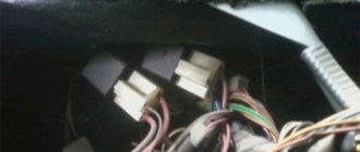
Rear Harness Terminal Blocks
Let's take a closer look at the above diagram:
- common terminal block of the wiring harness for connecting the wiring coming from the instrument panel (in the diagram under No. 1);
- terminal block of the wiring harness for connection with the wiring of the instrument panel of cars in the “standard” configuration and for connection to the side door harness for cars in the “luxury” configuration (in diagram No. 2);
- rear harness terminal block for connection to the instrument panel harness (No. 3);
- two 4-pin terminal blocks (for modifications 2112-3724558-10 16 valves). Indicated on the diagram as No. 4 and No. 5;
- side direction indicators (no. 6 – left, no. 7 – right);
- power supply to the individual lighting lamp (number 8 on the diagram);
- power supply for the general interior lighting lamp (No. 9);
- handbrake sensor connector (No. 11);
- rear lights (in the diagram No. 11 is left, No. 12 is right);
- interior temperature sensor connector (No. 13 in the diagram);
- connector for connecting 4 interior dome light switches (in the diagram under numbers 14,15,16 and 17);
- connector for trunk light (No. 18);
- reserve block of the wiring harness (in diagram No. 19). Can be used as a connector to connect to the side door wiring harness;
- block for connecting the wiring harness of the license plate lights (no. 20 in the diagram);
- The wiring grounding points are indicated in the diagram as A and A1.
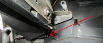
Wiring an additional wiring harness for VAZ 2112
Individual parts of the wiring can also be replaced with your own hands. Specifically, an additional wiring harness in the trunk of the car (pictured below).
It connects to the mains:
- rear window heating system;
- electric rear wiper gear;
- additional brake light;
- trunk lock electric motor.
The VAZ 2112 electrical wiring of this wiring harness has the following designations:
- Through the terminal block No. 1, the wiring harness is connected to the main wiring of the car. Includes 4 wires: red, yellow-blue, white-blue and pink-black;
- Block No. 2 is similar in functionality. Uses wires: green, white, black and red;
- Terminal No. 3 is responsible for the operation of the electric motor unit and the rear window wiper gearbox. The contacts are powered by 4 wires: black, pink-black, yellow-blue and white-blue;
- terminal blocks No. 4 and 5 are responsible for connecting the rear lights;
- Terminal No. 6 powers the trunk lock motor. Wires – white and black;
- terminal block No. 7 is responsible for connecting the heated rear window (two red wires);
- the additional brake light is powered from terminal block No. 8 (wires black and red).