Why is KXX used?
The purpose of the device is to ensure the flow of the fuel-air mixture inside the inlet manifold. The supply occurs bypassing the throttle valve, which is controlled by the gas pedal, through an additional channel XX.
The electromagnetic unit is responsible for controlling the IAC. Opening/closing involves changing the cross-sectional diameter of the passage channel.
Depending on the type of power unit, the idle air valve functions differently:
- Carburetor engine. The IAC is installed directly in the carburetor body, which makes it part of the forced IAC economizer system of the fuel system. The control unit is located in the engine compartment of the vehicle. The ignition timing is a signal for the unit that supplies power to the valve, which opens and gasoline is supplied to the intake manifold through the XX channel. When the ignition is turned off, the IAC is de-energized and the fuel supply stops. Adjusting the idle air valve is necessary to regulate the amount of gasoline supplied and is carried out by manipulating a special valve.
- Injection motor. The idle speed control is located in the throttle body as part of the electronic control system. The control electronic unit is usually mounted in the car interior under the front panel. Recording signals from sensors monitoring engine operating parameters, it analyzes them and transmits a control signal to the regulator. The device regulates the volume of air supplied to the manifold, ensuring the required idle speed.
- Diesel engine. The IAC is installed inside the high pressure fuel pump. The engine control unit located in the engine compartment is responsible for the controls. Commands to the valve are transmitted as a result of the reaction to the supply of fuel to the cylinders of the power unit.
How the regulator works
When the engine is idling, through an additional air supply channel, bypassing the closed throttle valve, the air necessary for its stable operation enters the engine. The cross section of this channel is regulated by IAC. The amount of air is taken into account by the mass air flow sensor (MAF). In accordance with its quantity, the controller supplies fuel to the engine through the fuel injectors.
When the engine is warmed up to operating temperature, the controller maintains idle speed. If the engine is not warmed up, the controller increases the speed using the regulator, ensuring it warms up at higher speeds.
Operating principle of the XX valve
At its core, the idle air valve is an electromechanical actuator operating under the control of an electronic unit that supplies electrical signals to open or close it.
In this case, the diameter of the flow section of the XX channel changes, supplying the required amount of fuel or air to the engine intake manifold.
Carburetor engines.
In gasoline carburetor engines, the XX solenoid valve is installed directly in the carburetor body and is part of the forced idle economizer system (ISP) of the fuel system.
The operation of the XX valve is controlled by the EPHH control unit installed in the engine compartment of the vehicle.
When the ignition is turned on, power is supplied from the control unit to the solenoid valve, which opens and supplies gasoline through the XX channel into the engine intake manifold.
When the ignition is turned off, the idle air valve is de-energized and cuts off the fuel supply.
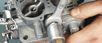
To adjust the amount of fuel supplied through the idle passage, an adjusting screw called the “idle screw” is installed in it.
Injection engines.
In gasoline injection engines, the idle air valve, more often called the “idle control valve,” is mounted in the throttle body and is part of the electronic engine control system (ECM).
Its operation is controlled by an electronic ECU (controller), located, as a rule, in the car interior under the front panel.
The control unit records signals from sensors that monitor individual engine operating parameters, processes the received information and issues a control signal to the idle speed controller.
Upon command from the ECU, the XX regulator increases or decreases the volume of air supplied through it to the engine inlet manifold, ensuring the specified XX speed.
Diesel engines.
In diesel engines, the idle air valve is installed in the housing of the high pressure fuel pump (HPF) and, just like in the injector, is connected to the engine ECU control unit located in the engine compartment.
But at the same time, it regulates the supply of fuel, not air, to the cylinders, providing the necessary idle speed.
Signs of a malfunction of the idle speed controller of the VAZ family (2114, 2110, etc.)
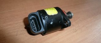
Idle Air Controller is a small device designed and installed in a modern car with the sole purpose of stabilizing the operation of the internal combustion engine at idle speed.
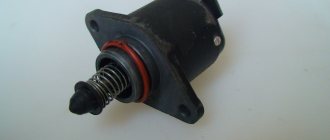
Appearance of the idle air control : a small “barrel” on one side of which there is a connector for power supply. on the other, there is a rod at the end of which there is a conical needle. Inside the sensor there is an electric motor that drives the rod and needle. Since the regulator is an actuator, it does not have the ability to self-diagnosis.
IAC calibration
- Before installation, you must remove the terminal from the battery
- Measure the distance from the end of the needle to the flange, it should be 23 mm or less.
- Install IAC back
- Turn the ignition key, but without starting the engine for 10-15 seconds. The controller is calibrating.
- Turn off the ignition again.
- Calibration is complete. You can start the engine and check the operation of the regulator.
Photo of idle speed sensor (рхх)
Types of valves
The set of actions and their sequence during an operation such as adjusting the idle air valve depends on the type of device:
- Solenoid. The electromagnet is a retractor coil with a core. Installed at the entrance to channel XX. Applying power causes the core to retract, opening the passage hole. De-energizing returns the core to its initial position, closing the channel.
- Rotary. The operating principle of the device is identical. The role of the core is played by a rotor that rotates in different directions, which changes the cross-section of the passage channel.
- Stepper. A ring magnet and four windings are the main elements of the device. Control signals are applied to one of the windings in turn, causing the rotor to rotate and smoothly adjust the channel cross-section.
Main types and design of XX valves
Depending on the engine type, three main types of solenoid valves are used:
- Solenoid;
- Rotary;
- Stepper.
The solenoid version is an electromagnet in the form of a retractor coil with a core installed at the entrance to the idle channel.
When power is applied to the coil, the core retracts, opening the channel through the hole.
When the coil is de-energized, the core returns to its initial position, locking the channel.
The rotary valve type works on the same principle as the solenoid valve. But instead of a core, a rotor is used, which rotates in different directions, smoothly changing the cross-section of the idle passage channel.
In this case, pulse-width modulation (PWM) is used, which provides a high frequency of control signals for opening or closing the valve.
A stepper idle valve is essentially an electric motor made in the form of a ring magnet and four windings.
Control signals from the ECU unit are applied alternately to one of the windings, as a result of which the rotor rotates, smoothly changing the cross-section of the passage channel from its full opening to its complete closing.
Purpose of the XX valve
The idle air valve ensures that the fuel-air mixture enters the engine inlet manifold through a separate additional channel XX, bypassing the throttle valve controlled by the accelerator pedal.
Depending on the type of engine, the idle air valve regulates the flow of either fuel or air.
In carburetor and diesel engines, it controls the supply of fuel to the inlet manifold, necessary for stable engine idle speed.
In gasoline injection engines, it supplies the required amount of air.
How does the regulator work?
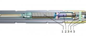
In everyday life, the IAC is often called a sensor, although in reality it is not one. The element is a stepper motor housed inside a non-separable housing. Only the spring-loaded rod with a cone-shaped tip protrudes outward. At the command of the ECU, the engine extends or retracts the rod to a certain distance.
The idle speed sensor is located in the throttle valve block, the working cone is extended into a small cross-section bypass channel. Since the engine starts and idles without pressing the accelerator pedal, the mentioned channel supplies air to the cylinders when the throttle is closed. The task of the IAC is to regulate the amount of air flow, blocking part of the flow area with a cone.
To better understand the issue, it is worth presenting the operating principle of the idle speed sensor in the form of an algorithm:
Note. If a warm engine is started, the controller immediately sets the IAC (IAC) rod to the operating position corresponding to normal idle speed.
Principle of operation
Next up is the question of how the idle air system valve, that is, the idle air regulator, works on car engines.
The KXX itself is an electromechanical actuator, which is controlled and controlled by the engine ECU. The latter supplies electrical signals, due to which the valve opens or closes. In this case, the diameter of the flow section of the idle channels changes, through which the required volume of air or fuel for the internal combustion engine enters the intake manifold.
To understand the operating principle on which the operation of the idle air control valve is based, it is worth considering the unit on different types of engines.
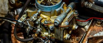
Carburetor
Carburetors running on gasoline must have such a solenoid valve. It is located in the carburetor body itself and is an integral part of the forced XX economizer.
This valve is controlled through the economizer control unit, which is located in the engine compartment. When you turn on the ignition, power is supplied from the unit to the regulator, it opens and supplies fuel to the manifold through the idle channel. By turning off the ignition, the power supply to the valve is stopped, and therefore the fuel supply is cut off.
To select the optimal volume of fuel for supply to the XX channel, the carburetor design provides a special adjustment screw.
This screw received a completely logical name and is referred to as the idle screw.
Injector
For gasoline injectors, the operating principle of the XX regulator is somewhat different. Structurally, it is located in the throttle body and is part of the electronic control system of the internal combustion engine.
The ECU is responsible for the operation of the valve. It records signals coming from monitoring installed sensors, processes the data and transmits control signals directly to the regulator itself. Due to commands from the ECU, the IAC can increase or decrease the volume of air entering the engine manifold, thereby maintaining the set speed.
Sensor diagnostic methods
The easiest way to check that the idle speed sensor is working is to start the engine and remove the power connector from the block. When the element is in good condition, the speed will drop sharply and the engine will stop - when the power supply is turned off, the spring will push the cone forward and the cross-section of the bypass channel will completely close. If the engine operation remains the same or changes slightly, move on to other testing methods.
The next stage of diagnostics is measuring the supply voltage, performed in this order:
Basically, on cars, you can check the performance of the stepper motor without removing it from the car. Using a multimeter, measure the resistance between the following pairs of contacts: A - B, C - D (it should be approximately 53 ohms). Then measure other pairs - A - C, B - D, on a working regulator the device will show infinity.
Further checking of the idle speed sensor is carried out as follows:
Advice. If a strong oil deposit is detected on the working part of the IAC, it is highly advisable to perform the procedure for cleaning the throttle and bypass channel - a similar picture is likely to be observed there.
To install a new regulator, be sure to remove the negative terminal of the battery. After assembly and connection, the IAC controller is calibrated - you need to turn on the ignition and wait 15 seconds. If the battery is not disconnected, the ECU will skip the calibration step, which may cause the engine to run unstably.
Source
How to identify a malfunction
Malfunction of the IAC is expressed in the following problems:
- The turnover is unstable.
- There were problems starting the engine: it does not start immediately, it stalls.
- Idle speed decreases with additional load (headlights, heater).
- The engine automatically stops working when the gearshift lever is moved to the neutral position.
Special diagnostic equipment will help determine the exact cause of engine malfunctions and determine the malfunction of the IAC. Depending on the complexity of the problem, adjustment, repair, or replacement of a spare part may be necessary.
How does the idle air control valve work?
Idle air valve operation
Much depends on the amount of air entering the fuel-air mixture injection system. An incorrect air to fuel ratio can lead to various consequences:
- excessive consumption of gasoline,
- insufficient degree of combustion of the mixture,
- premature wear of engine parts,
- reduction in engine power.
At idle speed, the throttle valve does not regulate the air flow into the intake manifold. To solve this problem and maintain the speed at the proper level, an idle speed valve is provided, which many mistakenly call a sensor.
On the one hand, this unit indirectly performs the functions of a sensor, but it also does another job, namely, it regulates the air supply for preparing the air-fuel mixture. Depending on the engine speed and operating mode, this unit regulates the amount of air entering the fuel system.
When the car is idling, the throttle valve is not engaged and cannot change its position. Accordingly, there is a need for a device that will provide air access to the injection system. This is where the XX (idle) valve comes to the rescue.
How to clean the idle air control?
Cleaning a proven IAC is considered using the example of a Chevrolet Niva:
- The engine compartment is opened and the battery is disconnected. To do this, you need to dismantle the cover of the air filter device, which is removed and put aside.
- The block is disconnected from the air controller. The connector is located on a thick rubberized corrugation connecting the intake manifold and the air filter cover. This block is attached using a special U-shaped bracket. During dismantling, it may jump out, so you need to be careful.
- Then the corrugation is disconnected from the intake manifold, it is fixed with a clamp. The same must be done with the rubberized pipe; it connects the corrugation to the valve cover of the power unit. The hose is fixed with an iron bracket.
- The thin pipe connected to the intake manifold is disconnected and removed along with it. This hose is pulled onto the fitting.
- Inside the pipes you can notice contamination in the form of carbon deposits and traces of engine fluid. All hoses must be cleaned and washed, after which they must be blown out. To complete the task, it is recommended to use a special cleaning agent or WD-40 liquid. The main thing is that there is a tube included with the cylinder.
- The idle speed sensor itself is made in a black plastic case and is installed in the intake manifold. The plug is disconnected from it and the two bolts that secure the device are unscrewed. The procedure is performed using a short screwdriver with a Phillips head; first, traces of sealant must be removed from the bolts. When dismantling the device, you must also remove the O-ring.
- The IAC is being cleaned, and fuel can also be used for this. The procedure is carried out using rags and cotton swabs. You cannot pour a lot of liquid into the mechanism so as not to damage it. After each cleaning, the sensor should oxidize and dry.
- It is recommended to remove dirt from the intake manifold; dirt is removed using rags. The idle speed sensor seat is cleaned throughout its entire depth. Contaminants are also removed from the device fitting.
- After cleaning, the entire structure is reassembled in the reverse order. A new rubber ring is installed on the idle speed sensor, after which the controller is mounted in place and fixed. The connector is connected to it, and the air filter device is installed back.
Where is the idle air valve and its control unit located?
Operating principle of the idle air valve
The valve is located directly in front of the damper and forces it into action. Its operation is regulated by a solenoid valve control unit, which is located in the engine compartment. If the placement of the valve depends solely on the design of the air intake system, then the location of the block varies depending on the car model.
The valve control unit can be installed:
- near the XX valve directly;
- under the windshield;
- in the generator area;
- anywhere in the engine compartment that is protected from water and high temperatures
The valve control unit is a sensitive device. It can be damaged due to mechanical stress, sudden temperature changes or moisture. In order to secure the unit, the designers suggest its location in the most protected areas of the engine compartment. The installation location directly depends on the design of the engines and other equipment located under the hood.
Poor idle in injection engines: problems and solutions. part 1
ATTENTION! There is not and will not be a simple universal answer to the question “why is idle bad?” You just need to familiarize yourself in detail with the many reasons that impair the performance of a car engine. You have the opportunity to familiarize yourself. The article you are reading is divided into several parts: 1. A little theory 2. Injection engines. Sensors 3. Practical recommendations
If you see that some words in the article are unfamiliar to you, I recommend that you first read the general short article
about automobile engines, about engine components and popular technical terms and abbreviations.
This is a starter article with a simple explanation of some automotive terminology. If you want to read the phrase “idling problems are solved by replacing this and that,” then try selling your car and riding the bus. Don't even rely on genius advice. Until you master simple basic knowledge about engines, you will have no luck in car repair.
Begin. How much money does it take to check if your car has a good engine? For this you need 1 kopeck. A coin worth 1 kopeck is placed on its edge on the hood of your car, supported with something so that it does not roll off, and then you need to start the engine. If the coin does not fall, then your engine is working perfectly. The engine rarely runs perfectly, especially at idle speed. What could be “wrong” at idle?
There are the following options: 1. The engine stops unexpectedly. It starts without problems, or it doesn’t start until it cools down. 2. Idle speed decreases, sometimes until the engine stops. 3. The engine stops if you release the gas. It is very difficult to stop a car at a traffic light without the engine stopping. 4. Idle speed is simply too high. 5. Idle speed increases for no reason, especially when driving, when changing gears, or engaging neutral gear. 6. Idle speed is generally unstable, the engine is simply “fooling around” and constantly changes speed, while becoming very loose. Some people like to say “the engine is cranking.” 7. After pressing the gas pedal and releasing the pedal, the idle speed rarely returns to its original state, or does not return at all. 8. Idle speed is generally unstable, and any manipulation of the throttle changes the idle speed. We will only consider most of the popular factors affecting idle speed.
A little theory. Short and simplified
For normal idle operation, the required amount of fuel and air must be supplied to the engine cylinders; at this point, the microdroplets of fuel in the mixture must be of minimal size, and we also need to ignite this mixture in the cylinder only at the moment we need, in other words, we must know what we need " ignition timing angle ". No more demands.
Injection engines were immediately divided into two groups: engines with a monoinjector and engines with distributed injection; among them, engines with direct injection can be distinguished. The monoinjector is a common replacement for the traditional carburetor, the monoinjector is even located in the place of the former carburetor, and forms the fuel mixture by supplying it to the engine intake manifold, and direct injection of gasoline goes directly into the engine cylinders. Distributed injection can be simultaneous, pair-parallel and phased. There is no such thing as "full" injection, it's homemade jargon.
The advantage of a mono-injector engine
: the engine is simpler and cheaper.
Let's continue. The pressure sensor in the intake manifold is no longer diaphragm, as in old engines, but piezoceramic. This sensor gives the controller a signal that depends on the pressure in the intake manifold, and the pressure depends on the air flow rate in the intake manifold. The sensor is needed to calculate the amount of air supplied to the engine cylinders. The pressure sensor may not be located on the intake manifold itself, but is connected to the manifold by an elastic tube. It happens that there is a rupture in the tube, or the tube is well clogged with dirt. A rupture in the tube can increase engine speed, and a dirty tube or faulty sensor reduces engine speed.
Of course, the pressure sensor
(English name
MAP ) in the intake manifold can be performed by a mass air flow sensor
(
MAF ), we skip this clarification.
Rarefied air (it is persistently called “vacuum”) from the engine intake manifold, as in carburetor engines, continues to be supplied to the vacuum brake booster. This means that if the idle speed is chronically too high, it is necessary to check the vacuum booster valve. A poorly functioning MAP or MAF will greatly impair engine performance under load.
The intake manifold air temperature and coolant temperature sensors provide the necessary signal to the electronic engine control unit, and improper operation of these sensors can change the idle speed, but this does not make it unstable. In some situations, the malfunction of these sensors leads to the fact that the engine starts well when cold and starts poorly when hot, or vice versa.
We do not consider all other engine sensors that are found in modern car models. They are not the basic sensors on which the stability of a car engine most depends.
What kind of idle air valve can it be?
On older cars with carburetor engines, mechanically actuated valves were installed. Their operation was regulated depending on the operating mode of the engine, but such a system did not justify itself, but was used for lack of a better one. The mechanism was set to a certain mode and did not have time to react in time to changes in the amount of fuel supplied to the engine and changes in the number of revolutions.
Subsequently, electronically controlled XX valves appeared, which began to be installed on injection cars. The control unit receives information from several sensors, processes it and accordingly regulates the valve capacity and its operating mode.
Checking the idle speed sensor
To check the functionality of the sensor you need: a tester.
Disconnect the electrical connector from the sensor. First of all, you need to check whether the voltage is coming to the sensor or not. Let's connect a voltmeter, the negative block - to the engine (ground), plus to the output of the wires marked with the letters A and D. The device should show that the voltage is at least 12 volts.
Let's check the sensor itself:
Now we connect the tester to the terminals of the wires marked with the letters A and B, after C and D - the resistance value should be equal to 53 Ohms. Then we measure the resistance in pairs: A and C, B and D. The resistance reading in this case should be infinitely large. Indications different from the above indicate a malfunction of the sensor and the need to replace it.
Removal, washing, installation
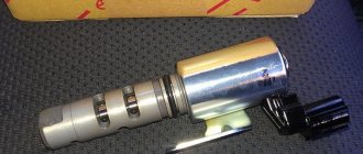
| This is what the idle air valve (IAC) looks like on a 1997 NISSAN CEFIRO. To remove it, you need to unscrew 2 bolts from the top and one from the bottom, naturally, having first removed all the connectors and the air duct tube from it. There is a metal gasket between the IAC and the intake manifold. Don't let her “go away”. It will be useful to us during assembly :-)). |
| After removal, we see a picture that is not at all pleasing to our eyes, especially the left one :-)… |
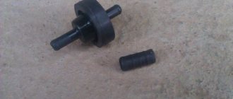
| The same thing, but disassembled. On the right are the valves themselves. The big one is the XX valve itself. The small ones are compensating valves for air conditioning and power steering. You need to remove them carefully, because they are spring-loaded, and searching throughout the garage for a small spring or valve is below average pleasure. They also have thin copper washers on them. Losing them is also undesirable :-). There is a rubber seal in the counter part of the IAC, which can also “slip away”. |
| This is what happened after washing with Unisma (domestic chemistry, a la WD-40). |
Everything is assembled without any frills, with one exception... I would strongly recommend sealing the junction of the valves and the body itself (coat the metal gasket on both sides) with sealant (just not too much, because the gaps there are very small), because any “left” leak air flow can cause problems with flow and starting. It is better to use a “black” or “gray” type of sealant. It is advisable to tighten the adjusting screw to approximately the same depth as it was originally. After installation, do not forget to connect all connectors! :-))
Who to entrust the adjustment to?
KXX is an important part in the power supply system of the power unit. The stable operation of any modern engine depends on its serviceability. You should not trust the adjustment of the idle air valve to unqualified performers.
At the MT-AVTO car service center, specialists with a high level of qualifications and extensive experience are at your service. Using high-tech equipment and modern tools, they will perform high-quality vehicle diagnostics and make the necessary repairs.
The thermal gap between the parts of the pusher and the valves is 0.15 mm for the normal functioning of the gas distribution mechanism. Idle air valves are checked on average every 20 thousand kilometers.
1500 RUR Cost of adjusting the idle air valve