Cars considered were 2003, 2004, 2005, 2006, 2007, 2008, 2009, 2010, 2011, 2012, 2013, 2014, 2015.
Location of Volkswagen T5 components in the engine compartment and interior.
1-Electronic ABS control unit 2-Air conditioning control unit - in the heater control panel 3-Air conditioning control unit (rear) - in the heater control panel 4-Antenna unit -if equipped 5-Side impact sensor, driver's side 6-Side impact sensor , rear left 7-Side impact sensor, passenger side 8-Side impact sensor, rear right 9-Anti-theft system control unit 10-Anti-theft alarm horn - intake system resonator 11-Audio output amplifier - under the front right seat - if equipped 12-Additional battery 1- under the front left seat - if equipped 13-Additional battery 2 (van) - in the kitchen cabinet 14-Additional heater control unit (Air Top3500) - under the body, on the right- if equipped 15-Control unit auxiliary heater (Thermo Top) - under the body, on the left - if equipped 16-Battery 17-Camping equipment control unit (caravan) 18-Diagnostic connector (DLC) 19-Diagnostic unit - dashboard 20-Driver's door electrical control unit 21 -Left rear door electrical control unit (with power sliding door) - left pillar 22-Passenger door electrical control unit 23-Right rear door electrical control unit (with power sliding door) - right pillar "0" 24-System control unit ESP (includes acceleration sensor, lateral movement sensor) 25-Roof lift control unit (van) 26-Electronic engine control unit - near the fuse/relay box in the engine compartment 1 27-System fan motor control unit cooling 1 - suspension (front left) 28-Cooling system fan motor control unit 2- in cooling system fan motor 2- if installed 29-Fuse/relay block, engine compartment 1 30-Fuse/relay block, engine compartment 2 31-Block fuse/relay block, engine compartment W 32-Fuse/relay block, instrument panel 1 - central part of the instrument panel 33-Fuse/relay block 2, instrument panel - under the fuse/relay block 1 of the instrument panel 34-Fuse/relay block, instrument panel 3 - behind the fuse/relay block, instrument panel 1/2 35-Fuse/relay block, instrument panel 4 - behind the fuse/relay block, instrument panel 1/2 36-Fuse/relay block, left seat - under the seat 37-Additional fuse 1 (differential lock switch, rear 10A) - left front pillar 38-Additional fuse 2 (additional heater 30A) - under the left seat 39-Additional fuse 3 (door electrical control unit, left rear 40A) - under the left seat (some models ) 40-Resistor 1 of the heater fan motor - near the rear heater fan motor 41-Resistor 2 of the heater fan motor - near the rear heater fan motor - if present 42-Sound signal 1 43-Sound signal 2- if present 44-Immobilizer control unit-combination devices 45-Ring antenna of the immobilizer - near the ignition switch 46-Instrument cluster control unit - instrument panel 47-Telephone control unit - behind the glove box 48-Multifunction control unit 1 - functions: Automatic transmission (automatic transmission), charging system (with additional battery ), cruise control, door/hood switch contact recognition, electrical load control, power windows, fuel pump, headlight washers, door mirror defroster, rear window defroster, hazard warning lights, windshield defroster, horn, turn indicators , instrument cluster illumination, interior lamps, automatic wipers, reversing lights, starter, sunroof, light switch, windshield washer, windshield wiper 49-Multifunctional control unit 2 - functions: Anti-theft system, central locking, electric rear mirrors view on the doors, power sliding door, power windows, sunroof 50-Navigation system control unit - in the navigation system display 51-Ambient air temperature sensor 52-Parking system control unit 53-Driver seat heating control unit 54-Passenger seat heating control unit 55-Steering wheel floor sensor - if equipped 56-Sunroof power control unit 57-SRS electronic control unit 58-Rear door open/close drive control unit - left "D" pillar - if equipped 59-Traffic information system control unit - under the instrument panel 60-Traffic information system control unit (alternative position) - under the instrument panel 61-Transfer box control unit (with 4WD) - rear final drive 62-Electronic transmission control unit (automatic transmission) - near the engine control unit 63- Voice synthesizer - under the front right seat - if equipped 64 - Vehicle speed sensor - gearbox (some models)
14.2. Fuses and relays
| GENERAL INFORMATION |
The location and purpose of relays and fuses may vary depending on the vehicle modification. The designation of the controlled and protected electrical circuit is printed on the block cover.
The main unit is located at the rear of the engine compartment on the driver's side. The additional unit in cars manufactured before 01/1991 is located above the glove box, and in cars manufactured since 01/1991 in the rear part of the engine compartment on the passenger side.
Relays can switch high currents over a distance, thereby allowing the use of weak control switches and wiring.
Unlike mechanical switches, relays can be controlled by more than one signal.
Some relays can operate on a timer, such as intermittent wipers or a heated windshield.
If a fault is detected in a circuit equipped with a relay, you should always remember that the problem may lie in the relay. The test can be done by replacing it with a known good relay.
To replace the relay, remove it from the socket and insert a new one. The relays in the main box are accessed in the same way as the fuses. Access to the relays located under the instrument panel is achieved after removing its upper part.
The sunroof actuator relay is located in the overhead console.
The battery is protected from short circuit by a fuse on the positive side.
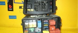
The main fuse and relay box is located on the right side of the engine compartment, near the bulkhead. It contains up to 24 fuses and almost as many relays (depending on the equipment). The list of fuses is on the back of the unit cover.
VWbus.club
The T5 transporter began production this year and has two fuse blocks installed on the left side of the engine compartment, two fuse and relay blocks in the central part of the dashboard and an additional block under the front left seat. The location of the blocks in the car did not change until the model was discontinued in the year.
T4 mounting blocks Installation diagrams for fuses and relays, as well as their purpose, will be discussed using the example of Volkswagen Transporter T4 vehicles from the year of manufacture in the maximum possible configurations. Blocks in the dashboard The main block is closed with a hinged plastic cover located to the left and below the steering column. If a part breaks down, starting the engine will be impossible.
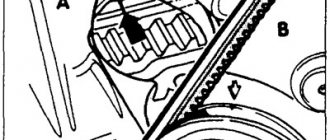
In addition, an additional relay can be found in the engine compartment. In particular, an element of the diesel internal combustion engine heating system is located on the dividing wall above the brake booster.
It will be useful: Which shock absorbers for the VAZ 2114 are better? original or analogues
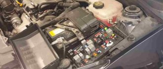
Model T5 As mentioned above, the T5 minibus model is equipped with several control devices for electrical appliances. One of them is in the engine compartment.
FANCLUB-VW-BUS.RU
In short, I was once again convinced that our officials are the best in the world. Tomorrow I’ll be at the dacha, I’ll remove the headlight and, as I understand it, I’ll need to re-solder the “positive” wiring. Vasya checked the errors and this is what I got: They work, so everything is in order.
Then the circuit goes into the depths of the control unit, a multifunctional electrical unit. Out of stupidity, I was immediately upset knowing about his “Siemens” reliability, giving him a disastrous verdict. But then I was alerted by the contacts marked “m” and “l” in it.
They are drawn going to the left, which means, logically, their continuation should be in the diagram above. Moved to the top level.
I saw this picture: The wiring enters according to the diagram from the right and exits again to the left. And at the same time, in the circuit there was a headlight switch, connections with them A84 and A85. Having subsequently opened the corresponding circuits, I found out that this is the very function “clearance on the right”, “clearance on the left.” Scratching the back of my head, the low beam of the Volkswagen T4 does not work that the wires ml in the circuit are the direction where the contacts creep further. In the diagram they go further to the left.
VW-BUS-CLUB
We check the fuses seen in this circuit a second time, just in case. The following diagram: Here we see that the ml wires pass through the diagram in transit.
Here we see that wire m comes out, along the way it has connection B and goes further to the front right side light bulb. I no longer needed the following diagram, and it is clear that the wires l will go out to the left marker in the same way. And have a similar connection.
Engines
Determination of turbine overflow using logs, TDI engines, etc. (rus.)
Photo report The most pressing problem in turbocharged engines is the occurrence of overblowing. This is especially true for diesel engines because... the formation of soot in the exhaust gases leads to its rapid accumulation inside the turbine and jamming of the geometry. First, let's try to figure out how the inflation pressure is adjusted, and then we will look at what the overblowing looks like in the logs.
Loss of power during acceleration, underblowing of the turbine, description of problems, removal of logs and diagnostics (rus.)
If problems arise related to loss of power during acceleration, both constant and variable loss of traction while driving. Loss of traction in the “full throttle” mode or the engine goes into emergency mode (it moves, but does not pull or pulls weakly), read this entire text carefully, and 9 out of 10 that this will help you determine the exact cause of the problem.
2.0L TDI engines for T5 2010 (rus.)
Engine letters: CAAA, CAAB, CAAC, CCHA. Device and principle of operation. Self-education program manual. Contents: 2.0L TDI engine, Cylinder block, Cylinder head, EGR system, Crankcase ventilation system, Exhaust manifold module, Intake manifold, Oil filter module, Cooling system with ball valve thermostat, 2.0L TDI engine management system, Pre-heating system, Common rail injection system, 2.0l TDI engine with twin turbochargers, Engine features: Cylinder block, Oil filter module, Twin turbocharging module, Twin-turbocharged engine management system, Twin-turbocharged engine charging system (twin-turbocharged ), Control system diagram, Electrical diagram, Maintenance and repair, Equipment and special tools, Instructions for working with twin turbocharging.
2.0 L TDI engines for T5 2010 (rus.)
Device and principle of operation. Self-study program 455 VW/Audi. Letter designations: 1.6 l 77 kW TDI engine (CLHA), 2.0 l 110 kW TDI engine (CRBC) As of the new T5 model 2010, Volkswagen Commercial Vehicles is switching to new injection technology in its engines: replacing good The proven 1.9L and 2.5L engines with pump injectors are being replaced by a new generation of 2.0L with CommonRail injection system. The new generation of engines ensures compliance with the stricter emission standards to be introduced in the future. Other important goals during their development were reducing fuel consumption and reducing operating costs. This self-study program covers the design and operation of new generation engines. Contents: Introduction, General description and technical specifications of 2.0L TDI engines, 2.0L TDI engine, Cylinder block, Cylinder head, EGR system, Crankcase ventilation system, Exhaust manifold module, Intake manifold, Oil filter module, Cooling system with thermostat with ball valve, 2.0L TDI engine management system, Engine management system, Pre-glow system, Common rail injection system, 2.0L TDI engine with two turbochargers, Engine design features, Cylinder block, Oil filter module, Twin turbocharging module, Twin-turbocharged engine control system, Twin-turbocharged (twin-turbocharged) engine supercharging system, Control system diagram, Electrical diagram, Maintenance and repair, Equipment and special tools, Guidelines for working on twin-turbocharged engines.
4-cylinder diesel engine AXB AXC BRR BRS (eng.)
Workshop Manual.
VW Transporter 2004 ➤ Repair manual for diesel engines with letter designation: AXB, AXC, BRR, BRS
. Edition 04.2013 These engines were installed on the following cars: Volkswagen Transporter T5 / Volkswagen Transporter T5 (model code: 7HA, 7HB, 7HH, 7HJ, 7JD, 7JE, 7JL, 7JZ) Volkswagen California T5 / Volkswagen California T5 (model code: 7HC) Volkswagen Multivan T5 / Volkswagen Multivan T5 (model code: 7HF, 7HM, 7HN) Contents (repair groups): 00 - Technical data, 10 - Removing and installing engine, 13 - Crankshaft group, 15 - Cylinder head, valve gear, 17 - Lubrication, 19 — Cooling, 20 — Fuel supply system, 21 — Turbocharging/supercharging, 23 — Mixture preparation — injection, 26 — Exhaust system, 28 — Glow plug system. 165 pages. 5 Mb.
Replacing a damaged fuse
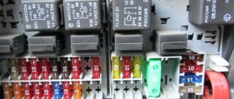
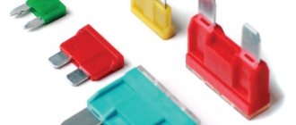
When replacing fuses in the Volkswagen Transporter T4 diesel and T5 unit, the rating of the parts can be determined by the color of the housing.
The most common types of inserts on T4 and T5 are:
- blue - 40 A;
- green - 30 A;
- white - 25 A;
- yellow - 20 A;
- blue - 15 A;
- red - 10 A;
- brown - 7.5 A;
- beige - 5 A.
Read more: Tuning the VAZ 2106 engine: how to increase power, install a compressor, instructions with photos and videos
Replacing fuses on a 2008 T5 Multivan begins with determining the location of the burnt fuse link.
For example, if the 15 A fuse for the cigarette lighter fails, you must do the following:
- Open the bottle container located on the central part of the front panel. Press the two levers and remove the container.
- Insert a screwdriver and carefully lift the cover. On a simpler Conveyor, the block cover is not closed by anything and opens without additional preparation.
- Take out the special tweezers there.
- Find the burnt insert. It can be determined by appearance or by checking it with a tester set to ringing.
- Using pliers, remove the insert and replace it. The new part must have a similar value. The use of homemade jumpers or more powerful fuses is unacceptable, as it can cause overheating of the electrical wiring and a fire. If the problem occurs on the way and there is no new fuse with the required rating, then it is better to remove such an insert from another section of the circuit that is not currently in use.
- Check that the cigarette lighter is working properly. If the fuse burns out immediately, then it is necessary to check the power circuit in more detail, determining the cause of the short circuit in it.
- Place the tweezers in place and close the lid.
- Loading …
The process of searching for and replacing the cigarette lighter fuse on a 2011 Volkswagen Multivan T5 is shown in a video from the author Lesha Lexx.
Brake system (ABS, EDS, ESP / Brake system)
ESP repair - soldering of the lateral acceleration sensor G200 (rus.)
Photo report ESP unit number 1J0 907 657 A / acceleration sensor 1J0 907 651A installed on cars: VW Golf 4 / Bora (1J), VW New Beetle (1C, 9C), VW Lupo (6X, 6E), VW Polo 3 (6N) , VW Sharan (7M), VW Transporter T5 (7H), Skoda Octavia (1U), Audi A2 (8Z), Audi A3 (8L), Audi TT (8N), SEAT Alhambra (7V), SEAT Ibiza / Cordoba (6K ), SEAT Leon / Toledo (1M). It is likely that this information will also apply to other cars.
Volkswagen Transporter T5 / Multivan 2003- : Brake system (rus.)
Repair and maintenance in color photos. Design features, checking and adjusting the brake system, checking the tightness of the hydraulic brake system, checking the degree of wear of brake pads and discs, checking the parking brake, checking the operation of the vacuum brake booster, bleeding the hydraulic brake system, replacing brake fluid in the hydraulic brake, master brake cylinder, replacement master brake cylinder reservoir, replacement of the master brake cylinder, vacuum brake booster, replacement of the vacuum booster, replacement of hydraulic brake hoses and tubes, replacement of brake hoses and tubes, removal and installation of the brake pedal, front wheel brakes, replacement of front wheel brake pads, replacing the front wheel brake caliper, replacing the front wheel brake disc, rear wheel brakes, replacing the rear wheel brake pads, replacing the rear wheel brake caliper, replacing the rear wheel brake disc, parking brake, adjusting the parking brake drive , replacement of the brake pads of the parking brake drive in version 1, replacement of the brake pads of the parking brake drive in version 2, replacement of the parking brake drive cables, replacement of the parking brake drive lever.
Fuses Karavel T6
In the sixth generation, the main fuse box is located under the glove compartment.
Photo example of a T6 fuse box
This is where the fuse for the cigarette lighter is located (circled in red).
As you can see, the location of the blocks in the Volkswagen Caravelle (Multivan) T5 and T6 is similar. However, their schemes are different.
Transmission, clutch
Elimination of backlash in the input shaft of 6-speed gearboxes 02N, 02M, 02Q, 02Z and 0A5 (rus.)
Photo report Signs of play: Poor clutch operation, difficulty disengaging first gear and reverse gear. In some cases, the clutch pedal does not return. The problem mainly occurs after people drive with a rattling flywheel.
7-speed dual clutch transmission 0BT T5, modification 2010 (rus.)
Device and principle of operation. Self-education program manual. Contents: Introduction, Gearbox selector, Gearbox design: Multi-disc clutch, Gearbox shafts, Force closure of secondary shaft gears, Parking lock, Power flow distribution, Reverse gear. Mechatronic unit, Electro-hydraulic control unit, Transmission hydraulic circuit, Transmission control system, Maintenance.
5-speed manual gearbox 0A4, Workshop Manual (eng.)
Repair manual for manual transmission 0A4.
Edition 04.2010 Five-speed gearbox 0A4
with gearbox letters:
FNE, FNC, GQQ, GTB, HGR, HDR, HJK, HNV, JCT, JCR, JCU, JCX, JCV, JQP, JVF, KBL, KBL, KBM, KCD, KCL, KJF, KQM, KPF, LHW, LEA, LHP, LLL, LUB, MDM, MDZ
installed on cars: Volkswagen Transporter T5 / Volkswagen Transporter T5 (7HA, 7HB, 7HH, 7HJ) 2003 - 2009 Contents (repair groups): 00 — Technical data, 30 — Clutch, 34 — Controls, housing, 35 — Gears, shafts, 39 — Final drive — differential. 319 pages. 7 Mb.
Block in the trunk
It is only present in cars with a second battery installed in the trunk.
Fuse box F -SF-, rear left (on vehicles with AXZ, BLV, BWS engines)
| But the number on the diagram | Denomination | Protected circuit |
| 1 | 30 | Fuse circuits No. 12-17, 28, 29-31 in the interior mounting blocks on the driver and passenger sides (only vehicles from May 2006); |
| 2 | 80 | Fuse circuits in the engine compartment MB No. 16-26, 49, 50 |
| 3 | 125 | Switch box power supply |
| 4 | 5 | Control unit for on-board network |
Fuse 2 (30) -S205-
In addition to the main unit, two more fuses are installed in the trunk: 70 A for the Limousine modification and 60 A for station wagon cars.
Electrical equipment
Volkswagen Transporter T5 / Multivan 2003- : Electrical equipment (rus.)
Repair and maintenance in color photos. Design features, diagnostics of electrical equipment faults, location of fuses and relays, removal and installation of mounting blocks in the cabin, battery, generator, starter, ignition switch, replacement of the ignition switch contact group, diesel engine control system, replacement of glow plugs for a car with a diesel engine, control system gasoline engine, lighting, light and sound alarms, checking and adjusting headlights, replacing lamps, headlights, fog lights, replacing side turn signal lights, replacing rear lights, replacing additional brake lights, removing and installing sound signals, replacing steering columns switches, removal and installation of electric motors for radiator fans of the engine cooling system, electric heating of the tailgate glass, instrument cluster, removal and installation of the car radio, replacement of sensors and switches, replacement of the brake light switch, replacement of the warning lamp sensor for emergency oil pressure drop, checking and replacement of the pointer sensor fuel level, checking and replacing the reverse light switch, replacing contact switches.
Transporter 2004 model. Electrical equipment (rus.)
Design and operation of components. Self-education program manual. CAN data bus, Location of electrical components, On-board power supply control unit, Control unit with display in the instrument cluster, Electric speedograph, Central control unit for the convenience system, Security alarm, Electric sliding door, Multifunction steering wheel, Cruise control, Radio, Loud voice communication DVE, Amplifiers, Antennas, Air conditioning, Maintenance.
Volkswagen Transporter T5 (7H) - Component Locations (eng.)
Component Locations Location of all electronic components, fuses and relays, ground connections, connector installation locations. The nominal value of fuses and what they are responsible for. Pinout of connectors. 243 pages! 3 Mb.
Volkswagen Transporter T5 (7H) - Wiring Diagrams (eng.)
Complete electrical circuits for Volkswagen Transporter T5 (7H) from 2003. 1.9L 63 kW — Turbodiesel engine (unit injectors), engine code AXC 1.9L 77 kW — Turbodiesel engine (unit injectors), engine code AXB 2.5L 96 kW — Turbodiesel engine (unit injectors), engine code AXD 2.5L 128 kW — Turbodiesel engine (unit injectors), engine code AX 2.0L 85 kW - Motronic, engine code AXA 3.2L 173 kW - engine (Motronic), engine code BDL 3.2L 173 kW - engine (Motronic), engine code BKK 3.2L 173 kW — engine (Motronic), engine code BDM 2.5L 96 kW — Turbodiesel engine, engine code BNZ 2.5L 128 kW — Turbodiesel engine, engine code BPC 1.9L 75 kW — Turbodiesel engine, engine code BRS 1.9L 62 kW — Turbodiesel engine, engine code BRR 6-speed automatic gearbox (09K) Auxiliary coolant heater Thermo Top Z / CB, Thermo Top Z / CD Anti-lock brake system (ABS) with electronic differential lock (EDL) and traction control system (TCS) and electronic stabilization program (ESP) and much more. 2616 pages! 62 Mb.
Navigation system Volkswagen RNS 310 and RNS 315 (rus.)
Operating manual in Russian. Option codes: RNS 310 - 7T2 and RNS 315 - 7UC. These navigation systems RNS 310 and RNS 315 were installed in Volkswagen Amarok, VW Caddy, VW Golf, VW Golf Plus, VW Jetta, VW Passat, VW Polo, VW Tiguan, VW Touran, VW Transporter/Caravelle, etc.
Volkswagen Transporter Time AttackTractoR › Logbook › Decoding fuses VW T5 2004-2009.
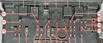
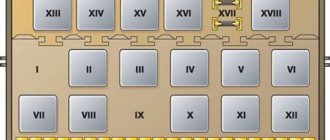
1 - (25A/30A) Heater/air conditioner (some models) 2 - (5A) Steering wheel position sensor 3 - (10A) Multifunction control unit 1 4 - (10A) Headlight range control 5 - (15A) Left headlight bulb 6 - ( 15A) Left headlight lamp 7 - (15A) Multifunction control unit 1 (interior lamp) 8 - (5A) Diagnostic connector (DLC) 9 - (15A) Brake light switch (brake pedal position sensor) 10 - (10A) Windshield wiper/ rear window wiper 11 — (5A) License plate light 12 — (15A) Cigarette lighter 13 — (5A) SRS electronic control unit 14 — (30A) Auxiliary heater heater/air conditioning 15 — Air conditioning 16 — (5A) Multifunction control unit 1 17 — (5A) Rear fog lights 18 — (5A) Instrument cluster control unit 19 — ^Audio system, instrument cluster control unit, multifunction control unit 1, navigation system, special vehicle equipment 20 — (5A) Front marker-left, left stop- signal, tail light - left 21 - (5A) Front marker - right, right brake light, tail light - right 22 - (10A) Passenger airbag off indicator, diagnostic connector (DLC), instrument cluster control unit 23 - (5A ) Starter relay (some models with manual transmission) 24 - Steering wheel position sensor 25 - air conditioning 26 - (30A) Headlight switch 27 - (15A) Right headlight lamp 28 - (15A) Headlight high beam indicator, right headlight 29 - Signal relay tailgate 30 - (10A) Windshield washer nozzle heaters, rear window wiper motor 31 - (30A) Multifunction control unit 1 (horn) 32 - (25A) Multifunction control unit 1 (windshield wiper motor) 33 - (15A) ) Audio system, navigation system, traffic information system control unit 34 - (25A) Automatic transmission control system, fuse/relay box, engine compartment 1 35 - (5A) Instrument cluster illumination 36 - (25A) Multifunction control unit 1 (turn indicators)
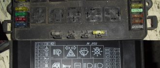
1 - (25A) Trailer electrical connector 2 - (5A) Anti-theft system 3 - (5A) Auxiliary air conditioner/heater fan, left, auxiliary air conditioner/heater fan, right 4 - (10A) Transfer case control unit 5 - (10A) Connector additional equipment (some models) 6 - (5A) Engine oil sensor 7 - (10A) Roof fan 8 - (5A) Parking system 9 - (5A) Steering column control unit 10 - (30A) Audio system 11 - (20A) ) Anti-theft alarm horn, multi-function control unit 2, power sliding door, rear door opener/close control unit 12 - (5A/10A) Brake light cut-off relay 13 - (5A) Cruise control main switch, multi-function control on steering wheel 14 — (5A) Telephone 15 — (5A) Automatic transmission 16 — (5A) Audio/navigation system, telephone 17 — (7.5A) Multifunction control unit 1 (interior lamp) 18 — (5A) Air conditioning (some models) 19 - (5A) Auto-dimming interior rearview mirror 20 - (10A) Multifunction control unit 1 (heated door mirrors) 21 - (5A) Anti-theft system 22 - (5A) Air conditioning 23 - (5A) Auxiliary heater 24 — (7.5A) Interior lamps 25 — (15A/25A) Heated seats 26 — (10A) Tachograph (if equipped) 27 — (15A) Fog lights 28 — (5A) Rearview mirror adjustment switch, rear mirror heaters type on the doors 29 — (25A) Additional heater 30 — (5A) Additional heater 31 — (25A) Sunroof 32 — (20A) Headlight washers 33 — (5A) Tachograph (if equipped) 34 — (15A) Additional equipment power supply connector 3 (rear) 35 - (10A) Multifunction control unit 1 (reversing light(s), with automatic transmission) 36 - (5A) Camping equipment control unit, special vehicle equipment
It will be useful: How to start in cold weather? tips on how to start a car in winter, rules and recommendations for starting a car engine in cold weather
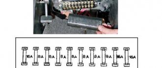
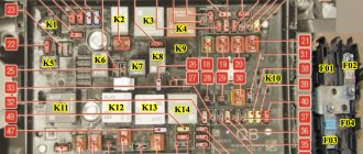
1 0 (5A) Cooling fan motor(s) 2 - (5A) Coolant pump relay 3 - (15A) Air conditioning 4 - (30A) Anti-lock brake system (ABS) 5 - (15A) Automatic transmission 6 — (30A) Anti-lock brake system (ABS) 7 — (5A) Cooling fan motor control unit 2 (some models) 8 — (15A) Engine control 9 — (5A) Engine control, main ignition circuit relay 10 — (5A) Coolant Pump Relay, Engine Management System 11 - 12 - Engine Control 13 - (10A) Engine Control 14 - Engine Control 15 - (10A) Reverse Light Switch 16 - Engine Control 17 - (5A) Anti-Lock Brake System (ABS) 18 — (5A) Multifunction control unit 1 19 — (5A) Brake light switch (brake pedal position sensor), clutch pedal position sensor 20 — Engine control 21 — (5A) Engine control 22 — (10A) Engine control 23 — (25A ) Automatic Transmission 24 - (5A) Automatic Transmission 25 - (25A) Engine Control 26 - (25A) Engine Control 27 - (5A) Coolant Pump Relay 28 - (15A) Horn (Some Models) 29 - (20A ) Brake booster vacuum pump 30 - (15A) Auxiliary A/C/Heater pump relay (some models), fuel pump (some models), fuel pump relay (some models) 31 - (15A) Engine management 32 - (30A) Engine management 33 - (5A) Coolant pump relay, engine control, glow plug relay 34 35 - (10A) Engine control 36 - (25A/40A) Starter relay (some models)
General vehicle documentation
Transporter 2004 model (rus.)
Design and description of the model. Self-education program manual. Brief description, Body, Passenger safety, Engines, Transmission, Chassis, Electrical equipment, Heating and air conditioning, Maintenance.
Volkswagen T5 2010 model year (rus.)
Self-education program manual.
Contents: 2010 T5 Model Line, Technical Specifications, Body, Emergency Tailgate Release, Passive Restraint Systems, Engine, Engine and Transmission Combinations, Transmissions, All-Wheel Drive System, Chassis, Brake System, Steering, Heater and Air Conditioning installation, Auxiliary heaters, Electrical equipment: Installation locations of control units, Data bus topology, Onboard power supply control unit J519, Lighting devices, Lane change assistant, Rear view camera, Front panel, Interface for connecting multimedia devices (MediaDeviceInterfaceBox), Head unit, telephone and navigation system, Head unit and radio navigation system, Antenna installation concept, Universal telephone connection kit (UHV). Volkswagen Transporter / Multivan T5 GP 2010->: General presentation of the vehicle (rus.)
Technical training.
Camper Volkswagen California 2004 (rus.)
Device and principle of operation. Self-study program 329 VW/Audi. Based on the 2004 Transporter, the new California combines the desires of travelers and business people whose work requires them to travel. And in this generation of the car, the layout of its interior with a kitchen unit under the front window and a linen closet at the rear left remains unchanged. But nevertheless, the new California is distinguished by balanced and detailed solutions and even greater comfort and flexibility in interior transformations. Some highlights of the California's exterior and interior design include: 2004 Transporter technology with diesel engines; aluminum folding roof with electro-hydraulic drive and load capacity of 50 kg; rear seat or bench with great transformation capabilities; bed with wooden frame in the roof; variety and flexibility of furniture. Contents: Introduction, Vehicle concept, Body, Devices, Water supply, Gas equipment, Electrical equipment, Heating and air conditioning.
If you have not found information on your car, look at the cars built on the platform of your car. Most likely, the information on repair and maintenance will be suitable for your car.
Volkswagen Transporter T5 and T4 fuse diagram: location and replacement methods
Replacing Volkswagen Transporter T5 and T4 fuses yourself
In addition, an additional relay can be found in the engine compartment. In particular, an element of the diesel internal combustion engine heating system is located on the dividing wall above the brake booster.
Model T5 As mentioned above, the T5 minibus model is equipped with several control devices for electrical appliances. One of them is a diagram of the Volkswagen transporter in the engine compartment. Its diagram and purpose of components is described below.
Volkswagen Transporter diagram Fuse block located in the engine compartment in the area of the battery Description of the block parts located in the engine compartment Description of the block parts located in the engine compartment Below is a diagram of the block located in the vehicle interior in the central area of the console, as well as a table describing its components .
It will be useful: Repair of the windshield wiper motor of the VAZ 2110
A block with elements located in the central part of the console in the cabin. Table of description of the power supply, which is located in the cabin of the minibus. Table of description of the power supply, which is located in the cabin of the minibus. Also, some modifications of minibuses Diagram of the Volkswagen transporter T5 are equipped with another device.
Connection point to ground next to the relay board. Connection point to ground in the rear door harness. Connection point to ground in the wiring harness of the dome light. Point of diagram of the Volkswagen conveyor to ground in the wiring harness of the dome light. R4. Connection in the R5 lamp harness.
Connection in the R6 lamp harness. Positive connection -1 - in the R7 lamp harness.
Double-filament lamp for the right headlight M1. Side light lamp, left MZ. Side light lamp, right Ground connection point in the rear headlight harness Ground connection point in the harness diagram Volkswagen headlight conveyor Diagram of the E4 headlight adjustment system. Switch for low beam headlights and warning light E Headlight adjustment resistance L Headlight adjustment lamp T2q.
Two-pin connector on the rear of the T5b relay board.
Five-pin connector under the switch cover on the steering wheel V Electric motor for adjusting the left headlight V Electric motor for adjusting the right headlight Point diagram Volkswagen conveyor to ground next to the relay board Turn switches, hazard lights, parking lights - diagram E2.
Turn signal switch.
Volkswagen transporter diagram The location of the fuse blocks on T4 cars produced in the years, whether gasoline engines or diesel engines, has not changed. But the purpose of the fuses is slightly different on buses before restyling.
The T5 transporter began production this year and has two fuse blocks installed on the left side of the engine compartment, two fuse and relay blocks in the central part of the dashboard and an additional block under the front left seat.
The layout of the Volkswagen transporter blocks in the car did not change until the model was discontinued last year.
T4 mounting blocks Schemes, Volkswagen Transporter fuses and relays, as well as their purpose will be considered using the example of Volkswagen Transporter T4 cars from the year of manufacture in the maximum possible configurations. Blocks in the dashboard The main block is closed with a hinged plastic cover located to the left and below the steering column.