The need to equip a trailer
Many enterprises have retrained their production to produce the latest prototypes of coupling devices. But the increase in such vehicles on the roads has led to their equipping with special signaling lights, which are similar to those of automobiles.
Recently, most motorists used the simplest towbar connection; moreover, the connection diagram for the towbar socket and the pinout of the towbar socket were not particularly complex, and motorists rarely touched on this issue.
Then, as a rule, single-color pinout conductors were used, the connection of which could be easily done using a special tester equipped with a loading light. But the situation changed radically after the market was flooded with cheap Chinese products.
Chinese equipment has colored conductors, which, it would seem, should simplify the connection procedure, but connecting the towbar wiring sometimes becomes a real headache for drivers.
Features of connecting the towbar socket
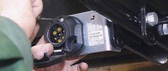
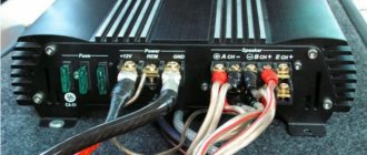
If you need to additionally attach the trailer hitch socket, it should be installed in the towbar socket, and then connect the contacts according to the pinout of the towbar connector, wiring diagram. Conscientious manufacturers include placement instructions in the box with the product they sell. If there is no such pinout, each car owner will have to determine the identity of certain contacts independently.
It is important to prepare all the necessary tools and materials for the job before you begin to loosen or tighten any bolts, screws, or other fasteners on a car, towbar or trailer hitch.
Among the mandatory tools and tools for preliminary preparation for connecting the trailer hitch (taking into account the electrical kit) are the following:
- the actual socket for the tow bar;
- dismantling devices (for removing the bumper, as an option - for trimming the rear bumper, if necessary);
- electrical tape, heat shrink;
- fastening elements, including a fastening plate;
- screwdrivers and wrenches (a set of different sizes of wrenches);
- soldering iron;
- wires (if they are not included in the kit, it is recommended to choose copper wires of the specified thickness);
- connecting terminals for the contact ends of the wires (can be sold together with the towbar, otherwise it’s easy to buy yourself at the market, bazaar or construction hypermarket);
- connection diagram for the towbar socket (preferably on paper).
For those car owners who decide to install a trailer hitch and install the socket themselves, the following rule should be taken into account: the thickness of each core in a stranded wire must be at least 1.5 mm.
General facts
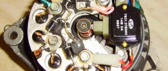
As you know, all electrical wiring in a car is hidden under the trim. The part of the wires that is needed to power the trailer, as a rule, runs from the battery to the dashboard. Then it passes through the entire interior to the rear bumper, and exits at a place called the towbar socket .
As for the trailer, everything is even simpler here.
From the trailer lights, the electrical wiring runs along its bottom and is attached to it using special clamps, usually metal. Next it goes to a connection point called the trailer fork .
Assembling a road train is not a tricky task, but problems are still possible. It is impossible to say exactly where to begin the assembly. Please note that the worst option is switching nodes in the car, which can lead to serious consequences.
How to connect a towbar socket to a car: trailer socket diagram
Everyone knows that there is a socket on the towbar, and there are plugs on trailers. Here is what many people think is a simple electrical circuit. But in fact, when connecting a trailer to a passenger car, you need to take into account a number of nuances. And it doesn’t matter whether you connect to an American car, a Euro car or a domestic product.
READ How to connect PS3 joystick to PS2
Each connector and plug has its own function. When connecting the towbar, trailer and car, you need to be extremely careful. There is a standard and non-standard pinout for Russia. Various features and tangles of wires often frighten those who decide to connect a car and a towed vehicle with their own hands.
But don't be alarmed. Everything has its own solution. If you decide to tackle the electrical wiring issue yourself, I will try to give you some practical advice and recommendations.
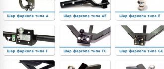
Connector options and connection diagrams
Initially, the towbar connection diagram had 7 contacts; they are also often called 7-pin connectors. For the first time such an innovation appeared in the United States, and a little later in Europe. Over time, the trailer connectors changed a little and already had 13 contacts, and sometimes all 15.
Also in those days, you could find special connectors that looked more like cables, but today they are used exclusively on narrow-profile types of equipment.
As for the countries of the former USSR, European types of connecting the towbar socket to the car have gained the most popularity here. The trailer fork is equipped with a safe and correct entry in the form of the so-called “male and female”.
This connection option is as convenient as possible, and even with zero visibility it is simply impossible to miss and not get hit.
The American analogue is similar in design to the European one. The differences concern only the electrical wiring of the signal. Also some American connections have 4 pin connectors. 13 pin connectors are installed on both European and American cars.
By the way, today the towbar socket in most cars that are delivered to the Russian Federation has a 13-pin connection. The advantage of this type of connection is that it makes it possible to connect additional elements such as fog lights and fully functional mobile homes.
There are also 15-pin options, which are often used on large tractors.
7 to 7 socket connection diagram
It’s even better if its cross-section is from one and a half square meters. You can splice the contacts of two headlights, reverse lights, brake lights, fog lights and side lights.
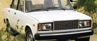
Universal connection diagram for a car trailer socket - the second method. Many models of modern cars have a towbar that allows you to tow a trailer.
What is this connected with? Before driving, check that all trailer warning lights are functioning properly.
It is advisable to use the services of experienced electricians who master the intricacies of switching and know the features of electrical circuits. This must be done correctly - through the towbar. As already mentioned, this method is not suitable for vehicles equipped with an on-board computer.
We recommend: Standards for testing and measuring electrical equipment
They don't use as much current and the relay will still function as before. Wrenches and screwdrivers. The next method involves changing the car's electrical system.
List of required materials: Various tools for removing the bumper. Remember that connection and installation work can only be carried out when the power from the vehicle battery is disconnected.
Lamps used in 8213 series trailers
It is used to control the connection of the trailer wires. At first glance, a simple procedure turns out to be not as simple as it was originally thought. Articles on the topic. Contact numbers and wire colors for a 13 pin socket. Correspondence table for pin connector.
The second contact group, which provides constant 12-volt power, is often not used. Before driving, check that all trailer warning lights are functioning properly. hitch the trailer
Step-by-step connection guide
- The connection diagram for a car trailer socket has the following order:
- First you need to cut the conductors to the required length, which is indicated in the diagram.
- Carefully clean and tin their ends, and then fix them in the socket.
- Assemble the harness into a corrugation and secure the socket. If you find any problem areas, then they need to be sealed.
- Take the resulting corrugation and stretch it as indicated in the installation diagram.
- Find the connector block and solder the ends, then connect the wires to the left and right lights.
- After all the manipulations, tighten the clamps thoroughly and hide the electrical wiring.
If you are not confident in your own abilities and do not have the necessary knowledge, then the best option would be to entrust this work to an experienced specialist.
A qualified technician knows all the intricacies of such work, and if problems arise, you can contact him again to correct the problem. Incorrect connection can lead to overheating of the electrical wiring and its complete failure.
Direct connection diagrams
If the towbar and trailer of a passenger car (and truck) are equipped with the appropriate connectors, then the electrical connection diagram will not be needed at all, since you just need to insert the socket into the socket.
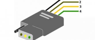
Pinout of 7-pin trailer socket Euro and RF
- Left side turn signal.
- Reversing lamp.
- Earth.
- Right side turn signal.
- License plate light and right side marker light.
- Brake light bulbs.
- Right side marker light.
US 7 pin trailer socket pinout
A special feature of the connector is the presence of a reverse contact and the absence of separation between the right and left rows of side lights. In some models of American cars, there is no separation between side lights and brake lights (they run on one wire).
Pinout diagram for 13-pin socket
- Left side turn signal.
- Rear fog lamp.
- Ground for terminals 1 to 8.
- Right side turn signal.
- Left side of dimensions and number plate illumination.
- Brake light lamp.
- The right side of the dimensions and number plate illumination.
- Reversing lamp.
- Constant voltage 12 volts 35 amps.
- The voltage is 12 volts 35 amps, supplied after the ignition is turned on.
- Ground for terminal.
- Signal wire.
- Ground for terminal 9.
Useful: All computer connectors: pinout and pinout of cables, sockets and PC plugs
When the car is not equipped with a modern electronic control unit. Thanks to this, electrical wires can be directly connected to existing electrical circuits. That is, the wires that come from the connector are connected to those connected to the rear lighting equipment.
Schemes of various types of sockets
On domestically produced cars, 7-pin electrical connectors are most often installed. They ensure the transmission of all signals from the vehicle to the BTS. If you need to connect a trailer instead of a cargo trailer, then use a 13-pin socket. For electrical wiring (pinout), double-insulated stranded wires with a core cross-section of at least 1.5 mm² are used. To protect the tourniquet from damage, it is placed in a corrugated sleeve.
7-pin socket pinout
If the car does not have a standard connector for connecting a trailer, then install a socket purchased in a store on a special plate near the towbar. In this case, pinout is done in a universal way. To do this, the wires are directly connected by soldering to the corresponding terminals of the contact blocks of the rear lights.
The pinout of the 7-pin socket is as follows:
On some European vehicles, the rear fog lamp contact may not be activated.
Control signals from the direction indicators are removed from both sides and connected to the socket using different wires. The indication of the rest of the lighting equipment can be taken from one block of rear lights.
13-pin socket pinout
Most imported cars are equipped with standard 13-pin connectors. If the car does not have a towbar, then in most cases a 7-pin socket is installed. When one of the vehicles has a 13-pin socket and the other has a 7-pin plug, the connection is made using an adapter.