Before looking specifically at the Zil 130 clutch, I would like to say a few words about the car itself. Zil 130 is a legendary Soviet truck, simple and unpretentious. The first series of cars was produced back in 1962, but even today you can meet these efficient workers on the streets of cities and villages. They are not afraid of bad roads and low-quality fuel. In addition, on the highway they can reach speeds of up to 100 kilometers per hour. Among the disadvantages of the model, it is perhaps worth noting the high fuel consumption, which can reach 30 liters per hundred kilometers.
Clutch ZIL 130
With proper care and timely maintenance, the Zil 130 can operate without problems for decades. There are living examples of this. However, it is advisable for any owner of this truck to have a good understanding of its structure in order to be able to carry out some necessary operations on their own. For example, you need to know how to adjust the ZIL 130 clutch. First, let's look at how it works.
Assembly and installation of the ZIL-5301 clutch
Assembling the pressure plate should be done in the reverse order of disassembly, on an auxiliary flywheel used as a device, placing a steel disk with a diameter of 300 mm and a thickness of 9.8 mm under the clutch pressure disk to adjust the position of the levers.
Install the flywheel on a bench, place the steel disk on it and install the clutch pressure plate on it (see Fig. 1).
Assemble the needle bearings by inserting a technological ball made of soft, oil-resistant rubber with a diameter of 8.8 into the hole in the lever. 9.5 mm, then insert nineteen needle rollers lubricated with Litol-24 grease between the rubber ball and the wall of the lever hole.
In a similar way, insert nineteen needle rollers into the second hole of the lever.
Align the hole in the support fork with the hole in the lever; in this case, the spherical protrusion of the inner end of the lever should be directed in the same direction as the threaded rod at the fork.
Insert a short finger into the aligned holes, pushing out the rubber ball.
Following the markings made during disassembly, install the lever in the groove between the pressure plate lugs, aligning the holes in the lever and the lugs.
Insert a long finger (see Fig. 2, a) into the aligned holes, pushing out the rubber ball.
In the absence of rubber balls, the assembly of needle rollers can be carried out by applying a layer of lubricant to the surface of the holes, to which the rollers seem to be glued. Moreover, needle rollers must be placed in the second hole after assembling the lever with the fork (see Fig. 2, b).
Install the remaining levers in the same way. In this case, the heads of the fingers should take a position in the direction of rotation.
Place heat-insulating washers on the protrusions of the pressure disk (Fig. → 3, a), and put pressure springs on the washers (see Fig. 1, e).
Having aligned the marks on the casing and the disk made during disassembly to maintain balance, install the clutch casing on the springs (see Fig. 1,e), directing them to the protrusions on the inner surface of the casing; in this case, the threaded ends of the support forks must fit into the holes of the casing.
To prevent the threaded rods of the lever forks from jumping out of the casing holes, it is advisable to put extensions on them in the form of thin-walled tubes
Align the holes on the casing support legs with the threaded holes of the auxiliary flywheel, install extended centering bolts and tighten the casing legs to the flywheel, tightening all the bolts gradually and sequentially.
Install the bushings into the shaped holes of the paired tangential spring plates, screw in the bolts securing these plates, tighten the bolts (the tightening torque should be 10.15 Nm), then lock them by bending the thin shoulder of the bushing onto the edge of the bolt head.
Screw the adjusting nuts onto the threaded rods of the forks until the end of the nut coincides with the end of the threaded rod of the fork.
Install the support clamping plates and locking plates on the adjusting nuts, screw in the bolts securing these plates and pre-tighten them until the ends of the support plates touch the casing.
Adjusting the clutch release levers
Without removing the assembled clutch pressure plate from the auxiliary flywheel, which is used as a device, it is necessary to adjust the position of the ends of the levers relative to the working surface of the pressure plate.
By rotating the adjusting nuts with a wrench (Fig. 4), set all the levers in such a position that the distance from the working surface of the pressure plate to the tops of the spherical protrusions at the inner ends of the levers is within 39.7. 40.7 mm. In this case, the ends of the levers must lie in the same plane, parallel to the working surface of the pressure plate with an accuracy of 0.5 mm.
Measurements should be made using a height gauge ShR-250 GOST 164-73, resting it on a steel disk that replaces the driven disk. Rice. 4 .
Adjusting and checking the location of the clutch release levers using a disc and height gauge
Having finished adjusting the clutch, you need to tighten the bolts securing the support plates (tightening torque 10.15 Nm), lock the bolts by bending one tendril of the locking plate along the edge of the bolt and lock the threaded connection of the adjusting nut with the threaded end of the fork (lock at one point). Unscrew the bolts securing the casing to the auxiliary flywheel and remove the disk assembly with the casing. In this case, all bolts should be unscrewed gradually and sequentially to avoid deformation of the clutch housing.
Clutch faults VAZ 2107
The main signs of a faulty VAZ 2107 clutch are:
- it is difficult to change gears;
- the driven disk slips;
- vibration appears;
- The pressure bearing whistles;
- the clutch is hard to disengage;
- The pedal does not return from the lower position.
Destruction of the pressure plate and basket casing can lead to very serious consequences
Almost any malfunction is accompanied by extraneous sounds - noise, knocking, whistling, etc.
Gears won't shift
If the gears are difficult to shift, an experienced driver will immediately tell that the clutch is moving. In other words, the clutch does not disengage completely. As a result, when starting from a stop, it is difficult to engage first gear, and when the pedal is pressed, the car moves slowly. The reasons for this situation may be:
- Increased distance between the thrust bearing support surface and the heel of the basket. It must be set within 4–5 mm, changing the length of the working cylinder rod.
- The spring sectors of the driven disk are warped. The disk needs to be replaced with a new one.
- The thickness of the driven disk has increased due to the stretching of the rivets securing the friction linings. The disk needs to be replaced with a new one.
- Jamming of the driven disk on the splines of the gearbox drive shaft. Both parts are defective and, if necessary, replaced with new ones.
- Lack of brake fluid in the master cylinder reservoir or accumulation of air bubbles in the hydraulic drive system. The working fluid is added to the required level, and the clutch hydraulics are pumped.
The clutch is slipping
The clutch may start to slip for the following reasons:
- there is no gap between the pressure bearing and the fifth basket;
- the clutch drive is not adjusted;
- oil got on the rubbing surfaces;
- the bypass channel in the main cylinder body is clogged;
- The clutch pedal does not return to its original position.
Such malfunctions are eliminated by adjusting the drive, replacing oil seals, cleaning the channel with wire, and identifying and correcting the causes of pedal sticking.
Clutch is jerky
If the clutch starts to jerk, it may be caused by the following:
- the driven disk is jammed on the splines of the gearbox drive shaft;
- oily areas have formed on the friction linings;
- the clutch hydraulic drive is not adjusted;
- the steel disk of the basket is warped, some friction springs have lost their elasticity;
- The driven disk is faulty.
In such situations, a complete clutch replacement is most often required.
Noise when engaging clutch
The appearance of grinding and rattling noises when releasing the clutch pedal may be due to the following:
- the pressure bearing is jammed due to lack of lubrication;
- The gearbox drive shaft bearing is jammed in the flywheel.
In both cases, the problem is solved by replacing the bearing.
Noise when disengaging the clutch
When you press the clutch pedal, you hear a knocking, clanging, rattling sound, and you can feel vibration on the gear lever. The reasons may be the following:
- the damper part of the driven disk (springs, sockets) is faulty;
- The splined connection of the driven disk and the gearbox drive shaft is badly worn;
- the return spring of the clutch fork has become detached, lost its elasticity or broken.
In all cases, worn elements should be replaced with new ones.
The pedal returns but the clutch does not work
Sometimes it happens that the clutch does not work, but the pedal returns to its original position. This may be due to the following situations:
- air entering the hydraulic drive system;
- wear of the sealing rings of the main and working cylinders;
- lack of working fluid in the tank.
In these cases, you should bleed the hydraulic drive, replace the rubber rings with new ones and add working fluid to the reservoir.
Tight grip
The softness of the clutch is determined by the force of pressure on the heel of the basket to retract the pressure plate. The magnitude of the force depends on the elasticity of the damper springs. Baskets from many manufacturers, including foreign ones, are suitable for the VAZ 2107 clutch. A tight pedal signals to the driver that the basket's life is coming to an end.
Installing the clutch on the engine
Place the driven disk, pointing the protruding part of the disk hub towards the flywheel, install the pressure disk assembly with the casing on the flywheel, aligning the existing marks on the casing and the flywheel, secure the casing to the flywheel, first tightening several fastening bolts by hand.
Center the driven disk relative to the flywheel using a special spline mandrel or transmission auxiliary input shaft by inserting it into the spline hole of the driven disk hub and into the crankshaft flange bearing.
Screw in the missing mounting bolts and finally tighten the casing to the flywheel, after placing spring washers under the bolt heads.
All bolts must be tightened gradually and sequentially with a torque of 28.36 Nm.
Remove the auxiliary shaft from the spline hole.
Install the clutch release fork, fork flange and secure it with bolts and spring washers.
Then put the fork lever on the small slots, aligning the marks on the lever and the end of the fork, insert and tighten the lever locking screw with the spring washer.
Some mechanics, due to inexperience, install the driven disk on the wrong side, although in principle it can be installed on the wrong side. But in this case, the disk will quickly fail.
Look at the section and place it as in the picture.
Spare parts for trucks
Full model range: GAZ-3307, 53, GAZ-3309, GAZ-66, 3308, 33081, 33086, GAZ-33104
Car clutch GAZ-3309, GAZ-3308, GAZ-33081 Sadko for diesel engine
The clutch of the GAZ-3309, GAZ-3308, GAZ-33081 Sadko (diesel engine D-245) is permanently closed, single-disk, dry, with a central pressure diaphragm spring and a damper device on the driven disk. Pressure disk 19 (Fig. 1) is connected to casing 10 by three groups of plates.
The clutch and release mechanism of the GAZ-3309, GAZ-3308, GAZ-33081 Sadko are located in the clutch housing 21, which is attached to the rear sheet of the engine with ten nuts 16 studs and a bolt, under which conical spring washers 15 are installed with the convex side to the nuts and the bolt head.
Centering the clutch housing relative to the axis of the engine crankshaft is carried out using two pins 20 pressed into the clutch housing. On the clutch housing there are 6 brackets for the rear engine mounts, which are secured with 5 bolts.
Rice. 1. Clutch GAZ-3309, GAZ-3308, GAZ-33081 Sadko (diesel engine D-245)
1 flywheel; 2, 5 - bolts; 3 - fork; 4 — rear cushion; 6 — rear engine mount bracket; 7 — protective ring; 8 — clutch; 9 — rivet of the friction lining; 10 - casing; 11 — support ring; 12, 20 — pins; 13 - bearing; 14 — gearbox input shaft; 15 — washer; 16 - nut; 17 — driven disk; 18 — disc pressure spring; 19 — pressure disk; 21 — clutch housing
There is no gap between the pressure spring 18 and the clutch bearing 8, so the inner ring of the bearing rotates at the engine crankshaft speed. During operation, the clutch does not require adjustments.
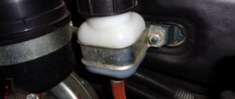
The clutch control drive for GAZ-3309, GAZ-3308, GAZ-33081 Sadko is hydraulic. The clutch master cylinder 15 (Fig. 2), mounted on the front panel of the cab, is actuated by the suspended pedal 20.
The master cylinder of the GAZ-3309, GAZ-3308, GAZ-33081 Sadko clutch is connected by a hose 2 to one of the sections of the three-section supply tank 1, equipped with an alarm sensor for an emergency drop in the brake fluid level (the other two sections of the tank supply the hydraulic drive of the dual-circuit service brake system).
Rice. 2. Clutch drive of GAZ-3309, GAZ-3308, GAZ-33081 Sadko cars
B - compensation hole; G - bypass hole; 1 - supply tank; 2 - supply hose; 3, 18 — fittings; 4, 23 — protective caps; 5, 24 — pushers; 6.33 — bushings; 7.34 - pistons; 8 — piston valve; 9, 14, 35 — cuffs; 10.32, 37 — springs; 11 - coupling; 12 - nut; 13 — thrust washer; 15 — clutch master cylinder; 16 — clutch master cylinder valve; 17 — thrust ring; 19 - pipeline; 20 - pedal; 21 - hose; 22 — clutch slave cylinder; 25 - cover; 26 — fork ring; 27 — fork support axis; 28, 30 — rollers; 29 - coupling pin; 31 — clutch bearing; 36 — spacer sleeve
The working cylinder 22, mounted on the upper part of the clutch housing, is connected to the main cylinder by a pipeline 19 and a hose 21, and is equipped with a valve to remove air from the hydraulic system. When the pedal is not pressed, the cavity under piston 7 of the main cylinder is connected to the reservoir through compensation hole B, which eliminates an increase in pressure in the hydraulic system and clutch slipping.
The bearing 31 of the GAZ-3309, GAZ-3308, GAZ-33081 clutch release clutch is pressed against the pressure spring with a force of 70-100 N (7-10 kgf) using spring 32 through piston 34, pusher 24, fork 3 (see. Fig. 1) and clutch 8. When the clutch linings wear out under the action of the pressure spring, the system takes a new position, compressing spring 32 (Fig. 2).
Excess fluid from the clutch slave cylinder GAZ-3309, GAZ-3308, GAZ-33081 Sadko enters the reservoir through a pipeline into the compensation hole in the master cylinder.
The existing bend in the length of the working cylinder for the movement of the piston provides (without adjustment) the calculated wear of the clutch linings. The position (travel) of the clutch pedal relative to the floor is regulated by changing the length of pusher 5. Repair work on the clutch can be carried out without removing the engine from the car.
Removing the clutch of a GAZ-3309, GAZ-3308, GAZ-33081 Sadko car
To remove the clutch, you must remove the gearbox and clutch housing.
To remove the clutch housing GAZ-3309, GAZ-3308, GAZ-33081 Sadko, you must do the following:
— disconnect the exhaust system pipe from the clutch housing; — Unscrew the fastening bolts and remove the cover of the clutch slave cylinder; — unscrew the nuts of the studs securing the clutch working cylinder, lift up the working cylinder assembled with the pusher, without disconnecting the hose;
The clutch basket does not press against the flywheel - why? | Thread Posted by Godek
Good day! Changing the clutch disc on the lawn.
Ildar (Einmyria) if they install a new slave, that’s why it doesn’t press, if you don’t install the wire, then your clutch won’t work
Vyacheslav (Eila) Then the washers should be there from new? After all, everything in a new car is new! Is that how it works?
Ildar (Einmyria) there is wear in both the flywheel and the basket, so it gives you 4-5mm
Ildar (Einmyria) and if you install a new basket and slave, then the wire is not needed
Vyacheslav (Eila) it seems to me that the flywheel is on the contrary. There is just a 4-5 mm recess for the basket, and the teeth on the flywheel are slightly eaten by the starter towards the starter and do not look. everything points to this!
Yury (Dell) Do you install everything as it should (flywheel, disk and basket) and it doesn’t press? Is the disc on the right side? Is the release lever not pressing on the petals?
Ildar (Einmyria) When I bought the car, my wingman stood on the contrary and pressed the basket
Yury (Dell) Disks from different manufacturers, and some do not fit correctly!
Bychok (Bhuvanesh) once the plant began to produce reinforced clutch. its strengthening consisted in changing the thickness of the driven disk; the damper springs were in rubber! a different basket was put on him. and in order to put a reinforced driven one on the old-style basket, you need to put washers between the flywheel and the basket, and put another pusher on the pg, and move the lever along the splines to one. The old dead clutch can no longer be found in stores. and you still come across cars with old baskets, as in this case. if you buy a new basket, the need for washers will disappear!
Vyacheslav (Eila) Thank you very much.
Bychok (Bhuvanesh) please contact
Rostislav (Arpita) how to install the driven disk which side
Farit (Trav) Rostislav, where the splined part protrudes more, is placed towards the flywheel.
Sergey (Gerard) had a STARCO clutch (petal), and so the petals broke at 50,000 thousand, didn’t bother, put a basket with old-style paws on this disc, the flight was normal. Who has what kind of clutch? Starko definitely doesn't have baskets.
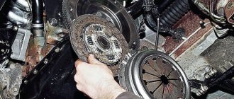
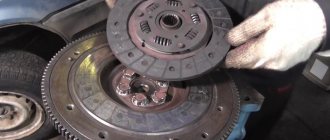
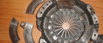
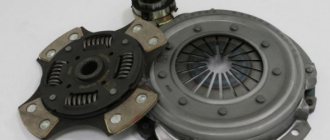
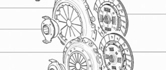
Clutch disc
In this article I want to tell you how I installed a KAMAZ clutch disc on a ZIL-130 diesel car. My car drove on a Zilov clutch disc for about 1-2 years and the disc broke. Many of my friends also often had their clutch disc break; they even had to change the clutch disc 3 times during the season. So I decided to try some changes. At first I had a Zilov clutch. Then I installed the clutch from the MTZ-80, and installed the disc from a KamAZ car.
KAMAZ clutch disc
clutch disc
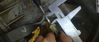
The clutch disc did not fit in diameter, but this is not a problem. We take the KAMAZ and ZIL disks, measure them and mark the difference in diameter. We grind off the excess on the KAMAZ clutch disc; this is about 6-7 mm in the circumference of the disc. Can be sanded down. Photo of the primary ZIL-130 in a KAMAZ wheel.
clutch disc and input shaft
Otherwise the disc is suitable and you can install it. Another difference is this. The fact is that the input shaft on a ZIL vehicle is smaller than the KAMAZ one and the input shaft engages with the KAMAZ clutch disc by half of the spline. But this is more than enough. I've already driven it for 4 years and installed the same clutch disc again.
Upon inspection, the disc was in excellent condition, and it will still travel the same amount. So don’t be afraid to install a KAMAZ clutch disc and drive confidently for many years. Watch the video, where I clearly show all the changes when installing the KAMAZ clutch disc.
ZIL-130 clutch with KAMAZ disk
Homemade products U Samodelkina OK | Topic author: Homemade
Which clutch disc is better to install on YuMZ?
Stanislav (Briggs) on balls
Sergey (Yamit) Zilovsky, he is turned around more than a yumz in a lathe, he is turned and walks without slipping.
Serik (Akiki) Of course on a soft connection.
In (Kipling) it is possible on balls or without a soft connection, it is at least factory-made
Serik (Akiki) Yes, it’s a disease. I changed the disk on the escovator twice a month, all the spare parts were broken out in a circle, still from raw meat
In (Kipling) then take the coulter from the grain seeder, cut off the hub, grind it, install the splines, stick the ferido and you will drive forever
In (Kipling) look at the bearing in the flywheel
Ring (Kaleb) You can install a clutch disc from the T150 and a clutch disc from the same or from Zila; they only fit the original basket.
Kolka (Kaleb) Only cut the disc.
Sergey (Yamit) which tractor do you want to install it on?
Kolka (Kaleb) At YuMZ, a guy and I have been installing an excavator for 2 years now, I haven’t adjusted it yet, I asked him about it on Friday. I understand, you won’t regret it.
Sergey (Yamit) Zilov disk and put it on a lathe and make it smaller.
Kolka (Kaleb) You can also make it from the coulter of the seeder, it also goes longer, I did this myself. You clamp the coulter more into the lathe by the hub and cut it to the size of the clutch disc, then cut off the rivets, knock out the hub from the seeder and install the hub from the clutch disc. Only the coulter You need to water it with water; it’s steely and doesn’t cut well. Then you rivet the hub, drill holes for the linings and rivet it. That's all.
Sergey (Yamit) also makes a coulter. but Zilovsky is better.
Kolka (Kaleb) Well, just put it there, just don’t forget the release lever from the T-150.
In (Kipling) It’s easier to buy a native one and go. It’s already 2021. Moreover, now there are discs on the shaft with a hub on balls. Very reliable.
Sergey (Yamit) THE BALLOODS ARE NOT BAD ALSO.. THEY DO NOT TEAR..
Yulia (Sharnel) I installed the Zilov disk on Yumz6 and it doesn’t turn on the speed
Sergey (Yamit) Zilovsky needs to be cut in a lathe. And the steel in the middle needs to be turned.
Sergey (Yamit) I’ll send you a photo and better plan.
GAZ-53: Installation of the driven clutch disc from ZIL-130
At one time, he worked for GAZ-53 for about three years. The car I received was wonderful, with very strange faults. Nowadays, this would be called a “bucket with nuts” and I think any driver would try to escape from it.
However, my turn for an apartment was approaching and therefore I had to persevere through all the troubles and fight for the KTU (technical readiness coefficient).
Before this car, I had a GAZ-52 and I didn’t drive it fast, but not a single engine failed for more than a year. The time had come to write it off and the boss, by hook or by crook, leased a 4-year-old GAZ-53, but for me it was like a promotion and I happily started driving it.
The work was mainly on city routes and it was not often necessary to travel up to 150 km out of town. At first it seemed that this was already progress, the car ran well, but again the engine turned out to be capricious.
Every week, half of the candles were necessarily thrown away and had to be removed and burned, but this was not a problem, due to the fact that a propane cutter was always present in the garage.
It will be useful: How can you replace flaxseed oil?
The engine had a slight vibration and driving the car was stupid. Other problems began to appear, for example, the clutch disc was missing for more than 1.5-2 months. At first it seemed that they had simply installed a bad disk, but after replacing it, the problem did not go away.
They installed any discs that the boss, having bored all his friends with, could get: driven discs GAZ-52 with a damper and GAZ-51 without a damper. However, nothing helped. It was decided at the consultation that there was some kind of non-parallelism between the axis of rotation of the engine and the gearbox.
Slowly, the boss found the parts, and they gave me time and I replaced the engine flywheel, clutch assembly and gearbox to boot. Everyone breathed a sigh of relief, but by a strange coincidence, a month later the clutch disc flew again.
The boss swore, took out another disk and I replaced it. Logically, it was necessary to change the driver, but I went on vacation and they put another one in my car. As they told me later, the car went to the line day after day, did its job, and the boss came to the conclusion that he would leave this driver, but by the end of the month his clutch disk also flew.
Here, according to the drivers, everyone was in a stupor. What is the reason? The boss made Solomon’s decision and decided to leave the old driver, because... He has already gotten the hang of driving a car and changes the clutch much faster. Why change it if all the bolts were turned by hand and the gearbox weighed about 50 kg.
When I returned from vacation, no one told me anything at first, but I found out how things were much later, in the free retelling of my colleagues.
I continued to change the clutch discs with enviable consistency, and the boss began to find them so quickly, as if he had already stocked them in advance. While I was removing the old disk, he had already brought a new one.
Soon, to my happiness, a man came to our organization in a rather shabby GAZ-53 and I asked how his clutch discs were running. To which he replied that on the state farm, almost everyone has homemade discs made from a disc harrow or cut-off ZIL-130 driven discs.
He also explained that on arable land, a GAZ car with 7 tons of beets or cabbage rolls up its own wheels. And I constantly transported an average of 1.5-2 tons and twice a month 4-5 tons.
The driver advised me to resharpen the disk from the ZIL and forget about the clutch forever, and also recommended a turner I could contact to perform this operation efficiently.
This is how it happens that an entire car depot does not know and does not know about such an alteration, but in the wilderness they have been using it for a long time and do not bother.
Here, we must pay tribute, the chef also took part. He found a ZIL clutch disc, made an agreement with a mechanic for repairs and issued an order to a turner for the alteration. Well, I have a day to help the turner.
The turner clamped the ZIL disk onto the damper and machined the splined joint. Then, I took an old GAZON disc and cut a splined connection out of it in the form of a bushing while I disassembled the clutch pressure plate. Next, a spline joint cut from a GAZon disk was pressed into a ZIL disk and the welder scalded it on both sides.
The next step was to clamp the cast-iron part of the pressure plate into a lathe and machine it from the inside so that the driven disc damper fits smoothly with a gap into the cast-iron part of the pressure plate.
Then, the GAZon input shaft with the driven clutch disc put on it was clamped into the machine chuck and the disc was machined with a cutting tool to the outer diameter of the GAZON clutch. The only thing is that I don’t quite remember whether the flywheel was sharpened or not, but I remember for sure that the turner said that it was necessary to sharpen it too.
After some time, another original disk flew, but a prepared replacement was already lying at the ready. I rearranged it, as expected, quickly. And as long as I worked in this GAZ car, the drive continued. I even changed the engine, but kept the clutch assembly.
I still suffered a lot with the engine on this car, but I forgot forever what a clutch is. The disk worked fine until I got an apartment, went on vacation, and finally left this job.
Now GAZonchiki are being produced with a new cabin, but still with a gasoline engine, and in view of the fact that they want to convert a fair number of cars to gas, it is quite possible that my experience of torment (there are no other words) may be useful to someone.
Adjusting the release levers (“claws”) of the ZIL-130 clutch basket
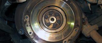
Clutch adjustment can be done on a dismantled pressure plate (for example, after replacing the clutch driven disc, or replacing the pressure plate pads or release bearing) or directly on the car through an open hatch in the flywheel. Let's consider the option of dismantling the gearbox and all clutch parts.
Unscrew the nuts from the gearbox mounting studs to dismantle it. After dismantling the gearbox, check the condition of the release bearing, clutch and tension spring. After removing the gearbox, turn the flywheel, then in the lower part of the casing you will have access to the pressure plate mounting bolts.
Dismantling is carried out in an inspection ditch using a special winch to remove the gearbox. After unscrewing 4 (four) fastening nuts, the gearbox is removed and lowered onto the pallet. Now unscrew the 8 (eight) bolts securing the pressure plate to the engine flywheel. And carefully, holding the driven disk (which is sandwiched between the flywheel and the basket), remove the pressure disk. All clutch parts are inspected. The release bearing is checked - it should rotate easily without making any extraneous sounds. Look at the working surface of the pressure plate feet. Determine the thickness of the friction linings of the driven disk. When all the parts have been rebuilt and replaced with new ones, it is necessary to adjust the four levers of the pressure plate or, as they are simply called, the “legs” of the clutch basket. To do this, you will need a flat plate, which is used as a spare flywheel of the ZIL-130 engine. If there is none, you need to purchase it at a disassembly.
The numbers indicate holes for attaching the pressure plate to the flywheel
Without removing the assembled clutch pressure plate (basket) from the auxiliary flywheel (used as a device), it is necessary to adjust the position of the levers relative to the working surface of the pressure plate.
Rotating the adjusting nuts with a wrench (Fig. 1, a), set all the levers in such a position that the distance from the working surface of the pressure plate to the tops of the spherical protrusions at the inner ends of the levers is within 39.7-40.7 mm . In this case, the ends of the levers must lie in the same plane, parallel to the working surface of the pressure plate with an accuracy of 0.5 mm, no more.
In the case where the clutch pressure plate is assembled in an adjustment device, the installation of the levers should be checked using a control plate, as shown in Fig. 1, b. In this case, the spherical protrusions of the levers should touch the control plate 2 installed on the hub of device 1. Having finished adjusting the clutch, you need to tighten the bolts securing the support plates (tightening torque 1.0-1.5 kgm). Then pin the bolts (in a figure eight) with soft annealed steel wire with a diameter of 1 mm.
Tighten the threaded connection of the adjusting nut with the threaded end of the fork at one point.
Unscrew the bolts securing the casing to the auxiliary flywheel and remove the pressure plate assembly with the casing. In this case, unscrew all the bolts gradually and sequentially to avoid deformation of the clutch housing.
This is what the adjustment lever or simply the ZIL 130 pressure disk foot looks like.
Adjustment lever with stand
Assembling the pressure plate (basket)
It is possible to adjust the release levers without removing the clutch basket from the car flywheel.
VAZ 2110 clutch: main components and signs of malfunction
The VAZ 2110 single-plate clutch has a central pressure spring, the drive operates by means of a cable, the casing is attached to the flywheel and to the pressure plate. In short, the following elements can be distinguished:
- a crankcase with a cover and support planes, through which the clutch assembly is attached to the frame;
- casing;
- pressure and driven disks, flywheel and release fork;
- release bearing that disengages the clutch;
- cable wire going to the pedal.
As for breakdowns, the main malfunctions of the VAZ 2110 clutch are associated with its wear. However, there are many other reasons for clutch failure:
- drives the clutch, that is, there is deformation of the driven disc, breakage of the friction linings, deformation of the pressure plate, problems with the cable, etc.;
- incomplete engagement of the clutch (slippage) - burning or wear of the friction linings, the appearance of oil deposits on the surface of the discs and flywheel, jamming of the drive, etc.;
- when the clutch is working normally, jerking is observed - jamming in the drive, damage or deformation of the pressure plate, etc.;
- when turning off, the appearance of noise is noticeable - the shutdown bearing is coming out of position;
By the way, if the clutch is not very worn out, replacing only the failed components in some cases allows you to save significantly. For example, installing a clutch disc will cost less than replacing the clutch basket and disc assembly. As a rule, after troubleshooting, only worn clutch parts are often replaced (for example, only the VAZ clutch disc or release bearing is replaced).
As for the selection of clutches, today the market offers both original parts and an alternative to domestic kits (imported clutch kits)
As practice shows, when choosing a VAZ 2110 clutch, price plays the last role, since it is important to purchase a quality solution
In fact, the top five kits are:
- Kraft Tech (Turkey) – parts are able to cool well and remove wear products on their own;
- LUK (Germany) - has the property of damping vibrations, which maximizes comfort;
- Valeo (France) – high reliability, softness and wear resistance;
- Sachs (Germany) - thanks to production technology, withstands heavy loads in various operating conditions;
- VIS (VazInterService) is a popular domestic solution that is not inferior to imported analogues in a number of indicators.
Adjusting the release levers (“claws”) of the ZIL-130 clutch basket
Clutch adjustment can be done on a dismantled pressure plate (for example, after replacing the clutch driven disc, or replacing the pressure plate pads or release bearing) or directly on the car through an open hatch in the flywheel. Let's consider the option of dismantling the gearbox and all clutch parts.
Unscrew the nuts from the gearbox mounting studs to dismantle it. After dismantling the gearbox, check the condition of the release bearing, clutch and tension spring. After removing the gearbox, turn the flywheel, then in the lower part of the casing you will have access to the pressure plate mounting bolts.
Dismantling is carried out in an inspection ditch using a special winch to remove the gearbox. After unscrewing 4 (four) fastening nuts, the gearbox is removed and lowered onto the pallet. Now unscrew the 8 (eight) bolts securing the pressure plate to the engine flywheel. And carefully, holding the driven disk (which is sandwiched between the flywheel and the basket), remove the pressure disk. All clutch parts are inspected. The release bearing is checked - it should rotate easily without making any extraneous sounds. Look at the working surface of the pressure plate feet. Determine the thickness of the friction linings of the driven disk. When all the parts have been rebuilt and replaced with new ones, it is necessary to adjust the four levers of the pressure plate or, as they are simply called, the “legs” of the clutch basket. To do this, you will need a flat plate, which is used as a spare flywheel of the ZIL-130 engine. If there is none, you need to purchase it at a disassembly.
ADJUSTING THE CLUTCH
Scroll the clutch basket so that the foot is accessible and visible. To adjust, we need a 19 mm wrench and a homemade device in the form of a curved screwdriver, as shown in the photo. Loosen the lock nut with a 19mm wrench on the clutch foot and use a curved wrench to move the foot to the release bearing with a 2mm free play gap. The clearance is needed so that the release bearing does not rotate constantly. And so we turn the clutch, adjusting each paw to the release lever. The most important thing is an even gap between the paws and the bearing.
Clutch adjustment
TESTS
When testing a car to see how the clutch works, first adjust the pedal free play. After some work, the clutch should be checked for play in each paw and the paws may need to be re-adjusted.
ZIL 130 truck clutches
Before looking specifically at the Zil 130 clutch, I would like to say a few words about the car itself. Zil 130 is a legendary Soviet truck, simple and unpretentious. The first series of cars was produced back in 1962, but even today you can meet these efficient workers on the streets of cities and villages. They are not afraid of bad roads and low-quality fuel. In addition, on the highway they can reach speeds of up to 100 kilometers per hour. Among the disadvantages of the model, it is perhaps worth noting the high fuel consumption, which can reach 30 liters per hundred kilometers.
With proper care and timely maintenance, the Zil 130 can operate without problems for decades. There are living examples of this. However, it is advisable for any owner of this truck to have a good understanding of its structure in order to be able to carry out some necessary operations on their own. For example, you need to know how to adjust the ZIL 130 clutch. First, let's look at how it works.
Clutch device
The Zil 130 truck clutch can be described as:
It is located in a cast iron crankcase, which is attached to the engine. Its casing is attached to the crankshaft flywheel using eight centering bolts. The pressing force is created by sixteen springs that are installed between the clutch housing and its pressure plate. Under them there are special heat-insulating washers. They are able to reduce the heating of springs. Thanks to these washers, the springs do not lose their elastic properties due to heating. Torque is transmitted from the casing to the driven disk through a pressure plate and four pairs of spring plates. The clutch release device consists of four levers connected to the fork and pressure plate with fingers. Between these pins and each lever are needle rollers. Spherical nuts are used as supports for the forks. They allow the forks to oscillate when the pressure plate moves.
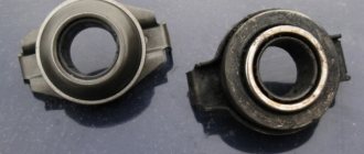
The clutch release clutch contains a release bearing, which is non-removable. Therefore, during operation, the amount of oil in this bearing cannot be replenished. The driven clutch disc is steel and has friction linings made from a pressed metal-asbestos composition. To release the clutch, a pedal with a shaft mounted in a bracket is used. The travel of this pedal is limited by the floor in the truck cab.
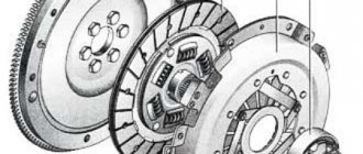
Clutch diagram ZIL 130
Clutch
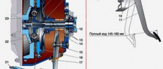
The ZIL-130 clutch (Fig. 37) is a single-plate dry clutch, installed in a cast iron crankcase 7. The clutch housing 9 is secured to the flywheel 2 of the crankshaft 1 with eight centering (special) bolts 23. The clutch pressure is created by sixteen springs installed between the clutch housing 9 and the clutch pressure plate ZIL-130 3. Heat-insulating washers are placed under the springs on the side of the pressure plate. The transmission of torque from the clutch housing 9 to the driven disk is carried out through the pressure disk 3 by four pairs of spring plates 4. The switching device consists of four levers 16, which are connected to the pressure disk and fork 18 with fingers 20. Needle rollers 22 are placed between the fingers 20 and the lever 16 The position of the clutch release levers 16 is adjusted during assembly using nuts 17, which are unscrewed after adjustment. During vehicle operation, the position of these levers is not adjusted.
Rice. 37. Clutch ZIL-130: 1 - crankshaft: 2 - flywheel; 3 — pressure disk; 4— spring plate; 5 — bushing of spring plates; 6 — plate fastening bolt; 7 - crankcase; 8 — pressure spring; 9 — casing; 10 — heat-insulating washer of the pressure spring; 11 — thrust bearing; 12 - coupling; 13 — clutch release spring; 11 — coupling guide; 15 — clutch release fork; 16 — clutch release lever; 17 — adjusting nut; 18— fork; 19 — support plate of the adjusting nut; 20 - fingers; 21 — crankcase cover; 22 — rollers; 23 — bolt securing the clutch housing to the flywheel; 24 - cotter pin; 25 — flywheel crown; 26 — driven disk; 27 — shield; 28 — drive shaft of the gearbox; 29 — drive shaft bearing.
The ZIL-130 clutch driven disc is made of steel, with friction linings, and has a friction-type torsional vibration damper (damper) (with dry friction of steel on steel). The elastic coupling of the damper is made up of eight springs 2 evenly spaced around the circumference (Fig. 38). The driven disk is balanced. Balancing is carried out by installing balancing plates 10 on the driven disk.
Rice. 38. Driven disk of clutch ZIL-130:1 - driven disk; 2 — spring of torsional vibration damper (damper); 3 - support plate; 4 — oil deflector; 5 — damper disk; 6 — driven disk hub; 7 - rivet; 8 — fractional damper pad; 9 — friction plate of the driven disk; 10 - balancing plate.
To disengage the ZIL-130 clutch, thrust bearing 11 is used (see Fig. 37), mounted on bearing coupling 12. Lubricant is placed in bearing 11 at the manufacturer and is not added during operation and repair. When repairing the clutch, the bearing should be replaced with a new one if necessary. With a correctly adjusted clutch drive, the gap between lever 16 and the clutch release bearing should be 3 - 4 mm. To disengage the clutch, use a pedal, the shaft of which is installed in a bracket mounted on the left side member of the ZIL-130 car frame. The lower end of lever 8 is connected by an adjustable rod 7 (Fig. 39) to lever 9 of the clutch release fork. The pedal travel is limited by the stop on the cabin floor.
Rice. 39. Clutch drive ZIL-130:1 - pedal; 2 - spring; 3 - spherical nut; 4 - lock nut; 5 — oiler for lubricating the clutch fork bushings; 6 - shaft; 7 - traction; 8 — intermediate lever; 9 — clutch release fork lever; 10 - oiler.
How to adjust the clutch?
In order for the clutch to always work reliably, it requires periodic adjustment. From time to time, owners of ZIL 130 trucks must adjust the free play of the clutch pedal, as well as the position of the clutch release levers. The pedal free play is adjusted using the adjusting nut. The gap between the release bearing and the clutch release levers should be from one and a half to three millimeters. In this case, the free play of the clutch pedal will be from thirty-five to fifty millimeters. This adjustment ensures full engagement and release of the clutch of the ZIL 130 truck. If the gap between the release bearing and the release levers is less than one and a half millimeters, then the release bearing will touch the release levers from time to time. This will be accompanied by clutch slipping and, as a result, increased wear of the bearing itself, as well as the release levers and friction linings.
Truck clutch release levers are adjusted during clutch assembly or repair using special ball nuts. This adjustment is required to allow smooth, skew-free movement of the pressure plate when disengaging the clutch. If it is neglected, the pressure plate will move away from the driven disk unevenly. As a result, increased wear of the entire assembly will occur, which will lead to its premature failure.
The clutch of a ZIL 130 truck may not disengage completely due to misalignment or warping of the driven disk, or if there is an uneven gap between the disks. Most often, such a nuisance occurs due to overheating as a result of prolonged slipping. This problem can be solved simply by replacing the damaged disks. If the friction linings are destroyed, they can create a wedge between the drive and driven discs. As a result, the clutch will not disengage completely. If this happens, you should disassemble the assembly and change the friction linings. When the clutch disengages, and the pressure plate still continues to slightly touch the driven disk, it is necessary to adjust the position of the release levers.
If the car starts moving with some jerking, then most likely this malfunction is due to the jamming of the release clutch located on the input shaft bearing cover. This happens because when the driver releases the clutch pedal, the clutch moves unevenly, first sticking and then jerking sharply. In addition, the clutch may engage abruptly due to warped discs. In this case, they will need to be replaced to eliminate the problem.
ZIL clutch maintenance
The single-plate clutch on a car is not adjustable. If necessary, the clutch is removed and adjusted.
Clutch maintenance includes cleaning from dirt and timely tightening the bolts securing the clutch housing to the cylinder block. These bolts are tightened (tightening torque 8-10 kgm). The bolt heads are secured with plates, the ears of which are bent to the edge of the bolt.
It will be useful Self-tightening of cylinder head bolts of a VAZ 2108: instructions, photos and videos
Caring for the clutch drive involves adjusting the free play of the pedal by changing the length of the rod. The clutch release bearing does not require lubrication during operation. The fork axles and clutch release pedal are lubricated according to the lubrication chart. See the figure for adjusting the clutch release drive.
Rice. Adjusting the free play of the clutch pedal: a - measuring the free play of the pedal using a device; b — adjustment of the pedal free play; A - the amount of free play of the clutch pedal
How to maximize the service life of a node?
In order for the Zil 130 truck to need repair as little as possible, it is necessary to operate it in compliance with several simple rules. You can move away in both first and second gear. You should try to release the clutch pedal as smoothly as possible. When parked with the engine running, do not keep your foot on the pedal. In addition, the pedals should not be left partially pressed while driving. This leads to premature wear and early failure of the entire assembly. You should not drive or change gears at high engine speeds. The adjustments described above must be made periodically. Following these simple rules will help maintain the functionality of the unit for as long as possible, as well as eliminate unexpected breakdowns.