Replacing the camshaft along with the housing on a VAZ 2101-2107
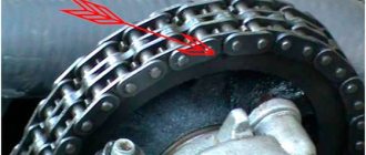
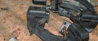
After purchasing my Kopeyka, I began to slowly repair it and the first thing I did was check the engine, since it rattled terribly. The previous owner said that the valve had burned out, but after removing the valve cover it turned out that the reason was somewhat more serious. This is what I saw after removing the valve covers:
As you can see, the camshaft housing was broken and a piece was lying in the head on top. Moreover, nearby in the same pile lay another rocker with a spring. It is not surprising that the previous owner of the VAZ 2101 thought that the valve had burned out, since the symptoms were similar - one cylinder was not working. Below I will tell you in more detail about the repair of a VAZ 2101-2107 with similar problems.
Replacing the camshaft with a pencil case on a VAZ 2101-2107 with your own hands
So, the first thing I did was go and buy another camshaft from a guy. Of course, I didn’t count on a new one, but as it turned out, it was in vain. This guy took out a camshaft wrapped in paper from the times of the USSR. And along with it he gave away a set of rockers. For this purchase I gave him 750 rubles. Although in the store these new parts cost at least 2,000 rubles.
First of all, we remove the valve cover by unscrewing all its fastening nuts with a 10mm wrench, after which we get this picture:
Now you need to use a flat screwdriver to bend the washer under the camshaft star mounting nut:
And unscrew the nut with a 17mm wrench, as shown in the photo below:
Now unscrew the timing chain tensioner bolt, which is located on the front right side:
Once the chain is loosened, you can gently tap on the inside of the sprocket to make it pop off:
Next, you can begin to unscrew the nuts securing the camshaft cover on the VAZ 2101-2107, as shown in the photo below:
And then you can remove the housing along with the engine camshaft by simply grasping it and pulling upward with a certain force:
The final result of the work can be seen in the picture below:
Now we take new rockers and install them in place of the old ones. This is necessary, since the old ones already have wear and tear and adjusting the valves will be quite problematic, and you may not be able to get rid of the knocking at all. Rockers are quite easy to change. You need to lift it all the way up and it can be removed without problems:
It is also advisable to replace the springs, since they cost pennies, only 3 rubles apiece. New rockers are installed without any sequence. If you install old ones, then they need to be installed in the same order in which they stood.
Then we take the new camshaft assembly 2101-2107 and install it on the cylinder head, after which we tighten the nuts with a torque wrench:
They should be tightened in a strictly defined sequence, as shown in the diagram:
A force of 18 to 21 Nm is required. Do not exceed the specified value range as this may damage the threads. After installation, we put the sprocket and chain back on and be sure to adjust the valves on the VAZ 2101-07
We start the engine and check how everything works, and if necessary, adjust the valves again! I succeeded on the first try and quite successfully, the motor now works as it should.
How to remove the camshaft
Diagnostics, repairs and measurements of the shaft are carried out only after it is removed from the engine. To work, you need to prepare 13 mm and 10 mm socket wrenches, 17 mm open-end and torque wrenches, as well as pliers.
Dismantling is carried out in the following sequence:
- The car starts on a level surface.
- The air filter housing is removed.
- Using pliers, the throttle cable is removed from the carburetor, as well as the longitudinal rod of the throttle valve.
- It is better to move the fuel hose to the side and secure it.
- Using a 10mm wrench, you need to unscrew the fastenings of the chain tensioner to the cylinder head and remove it.
- Using a 10mm wrench, unscrew the nuts that secure the valve cover.
- Now the cover is easily removed, and after it the rubber gasket is also removed.
- Using a slotted screwdriver, you need to straighten the lock washer, which is located in the place where the shaft star is attached.
- To perform the following work, you need to put the gearbox in first speed. Then you can use a 17mm wrench to unscrew the bolt that secures the camshaft gear.
- Now it is easy to remove it along with the chain.
- Now is the time to remove all the nuts that secure the camshaft to the bed. The key to 13 will help us with this.
- Now the camshaft is easy to remove along with the “bed”.
- Using a 10mm wrench, unscrew the bolts that secure the flange and the flange is disconnected.
- The camshaft is now easy to remove from the “bed”.
Tightening torques for cylinder head VAZ 2107
- 25 0 11k
- 111 0 96k
When assembling the cylinder head after replacing the gasket or repairing the cylinder head, it is important to tighten the bolts to the torque recommended by the automaker. But different instructions suggest using two different schemes for tightening the VAZ-2107 cylinder head with a torque wrench. Let's figure out what is their difference, and how the cylinder head is tightened on a VAZ 2107 , and with what force.
The table below shows both options for the cylinder head tightening torque diagram on a “classic” VAZ, depending on the type of bolt. Because classic bolts require only two passes , but modern torsion bolts , due to their properties, require four passes . In the article we will look at everything in more detail.
| Bolt type | Diagram and tightening torques of the VAZ-2107 cylinder head bolts |
| Classic bolts | During the first pass, the bolts are tightened to 4.0 kgf/m. During the second pass , tighten the bolts with a torque of 11.5 kgf/m. Bolt No. 11 size M8x45 is tightened with a torque of 3.8 kgf/m. |
| Torsion bolts with elastic deformation | On the first pass , tighten the bolts with a torque of 2.0 kgf/m. During the second pass, it is necessary to tighten with a force of 8 kgf/m. During the third pass, tighten all the bolts at an angle of 90 degrees. For the fourth, you need to tighten all the bolts 90 degrees again. Bolt No. 11 size M8x45 is tightened with a torque of 3.8 kgf/m. |
Why is correct tightening of the VAZ-2107 cylinder head important?
If you have replaced the cylinder head gasket, and besides major repairs, this is practically the only reason to disassemble the cylinder head, then the exact sequence and tightening torque of the VAZ-2107 cylinder head are critically important for the correct operation of the engine. Because any discrepancies in the fit of the valve cover lead to problems in the engine processes.
If the cylinder head of the VAZ-2107 is not tightened, then the parts of the engine will not be pressed against each other enough, even despite the presence of a gasket. The result is a drop in compression and burnout of the gasket. Also, working gases from the cylinders can enter the channels of the lubrication or cooling system and lead to the entry of these technical fluids into the combustion chamber. And this is already very bad - antifreeze in the oil will lead to insufficient lubrication of engine parts with all the ensuing consequences.
Antifreeze in VAZ 2107 engine oil
Traces of burnout of the cylinder head gasket on the cylinder block of a VAZ 2107
You also cannot tighten the cylinder head cover - this can damage it. Either cracks will appear in it immediately, or tension will arise, which will lead to this in the future. Also common is bolt rupture and thread stripping.
If you tighten the bolts in one place and not tighten them in another, the cylinder head of a VAZ-2107 car or its cover may warp. This will result in gaps that the gasket cannot compensate for. The result is the same as with loose bolts.
Tightening torques for the VAZ-2107 block head on carburetor and injection engines
For the most part, the “seven” was equipped with carburetor engines of various modifications. Moreover, the most common version was a 1.5 liter engine with 77 hp. Although modifications of 1.3, 1.4 and 1.6 liters were also produced. There is no fundamental difference in the tightening torque of the cylinder head of the VAZ 2107 injector and carburetor.
The procedure for tightening the cylinder head bolts on a VAZ 2107 engine
The cylinder head of an injection engine differs structurally only in the enlarged “windows” of the intake manifold channels, because the injector needs a little more air than the carburetor. But the tightening force of the VAZ-2107 cylinder head for such engines will be the same.
The instruction manual for the VAZ Seven contains clear data. Firstly , the tightening order is important (see picture). Secondly , first you tighten the bolts by hand, and then tighten bolts No. 1-10 in two stages with the force indicated in the table (in newton and kilogram per meter). Bolt No. 11 is reached last, in one approach, with a force of 3.8 kgf/m.
| Tightening stage | Rated torque, Nm (kgf/m) | Minimum, N m (kgf/m) | Maximum, N m (kgf/m) |
| Preliminary | 39,2 (4,0) | 33,3 (3,4) | 41,16 (4,2) |
| Final | 112,7 (11,5) | 95,94 (9,79) | 118,38 (12,08) |
Tightening the cylinder head of the VAZ 2107 - second option
On some newer “sevens”, not ordinary M12x120x1.25 bolts were used to fasten the cylinder head, but torsion bar bolts - M12x115x1.25. Therefore, in addition to the first option of the sequence and degree of tightening, there is another option with data on the tightening force of the VAZ-2107 cylinder head. The process itself looks like this:
- Stage 1. Tightening the bolts to a torque of 2.0 kgf/m.
- Stage 2. Second tightening with a torque of 7.5-8.5 kgf/m.
- Stage 3. Turn each bolt 90 degrees.
- Stage 4. One more turn of all bolts by 90°.
- Stage 5. Tighten bolt No. 11 with a force of 3.8 kgf/m.
Different bolts and tightening degree of the VAZ-2107 cylinder head. What is the difference
The “classic” was originally equipped from the factory with ordinary M12x120x1.25 bolts for a 19mm head. Their original catalog number was 2101-1003271 or 21213-1003271. The second number suggests that such bolts were also used on the VAZ-21213 Niva, which is why they are also called “Niva bolts”. Another colloquial name is “penny”. But most often they are simply identified as “cylinder head bolts for an old-style classic.”
Checking the alignment of the timing marks
If you do not match the crankshaft and camshaft marks, the engine will not operate correctly. Setting timing marks on a VAZ 2107 injector is no different from the same procedure on carburetor engines. The mark on the crankshaft pulley should align with the mark on the front engine cover. And the point on the rim of the camshaft sprocket should be opposite the beacon on the bed.
Align the mark on the star with the protrusion
When you put on the sprocket, lock the camshaft so that it is stationary. Do not tighten the star nut all the way. Align the marks on the camshaft by turning the sprocket. The chain should remain in its original position, so throw the links until you reach the alignment of the mark and the ebb on the bed. Then use the wrench to move the crankshaft a quarter turn counterclockwise. Turn the crankshaft back so that the marks on it match. When the marks are aligned on both the crankshaft and the camshaft, tighten the nut on the camshaft sprocket with a torque wrench. Tightening torque – 5 kgf*m. Adjust the chain tension using the tensioner.
FastFlo › Blog › all about VAZ 2107 (09)
description of the VAZ 2107 car engine
description of the VAZ 2107 engine design
Depending on the modification, one of four engines can be installed on a VAZ 2107 car: 2103, 2104 (1.5 l volume) or 2106, 21067 (1.6 l volume).
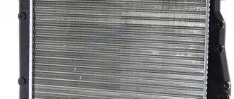
The engine of the VAZ 2107
is a gasoline, four-stroke, four-cylinder, in-line, eight-valve, with an overhead camshaft.
Engines 2103 and 2106 are carburetor, and engines 2104 and 21067 are with distributed fuel injection. The 2104 engine is based on the 2103 engine, so the cylinder block, connecting rod and piston group, timing drive and crankshaft have the same design and dimensions. Engine 21067 is based on engine 2106. Since engines 21067 and 2104 have different cylinder diameters, the pistons and rings are therefore not interchangeable. The timing drive parts and crankshafts of these engines are identical. On the camshaft drive cover of injection engines there are brackets for installing the crankshaft position sensor. Engines of VAZ 2107 cars equipped with an injection system comply with EURO II exhaust gas toxicity standards. Distributed fuel injection with a fuel vapor recovery system and a catalytic converter allows you to reduce fuel consumption and make it easier to start the engine on a VAZ 2107 in cold weather. The ignition system of engines 2104 and 21067 is included in the control system. The functions of the ignition distributor on a VAZ 2107 car are performed by an electronic engine control unit. The cylinder block
is cast from high-strength cast iron.
The engine cylinders are bored into the block and honed. By diameter, the cylinders are divided into 5 classes every 0.01 mm and are marked on the lower plane of the block with the letters A, B, C, D and E. The cylinders are arranged vertically in one row. The crankshaft
of the VAZ 2107 engine, cast from high-strength cast iron, is installed in the lower part of the cylinder block on five support journals.
The crankshaft rotates in steel-aluminum liners; a layer of aluminum-tin alloy is applied to the steel base. The holes for the main bearings are machined together with the bearing caps, so the bearing caps are not interchangeable. On the outer surfaces of the main bearing caps there are marks corresponding to their serial number (counted from the front end of the crankshaft). To prevent axial movement of the crankshaft, two thrust half-rings are installed in the grooves of its rear support - steel-aluminum and metal-ceramic. The camshaft drive cover contains a front crankshaft oil seal, which “works” along the outer surface of the pulley. The rear crankshaft oil seal is pressed into a holder attached to the cylinder block and “works” along the surface of the crankshaft flange. The front bearing of the gearbox input shaft is pressed into the rear end of the crankshaft. The connecting rod
is steel, forged.
The lower head of the connecting rod is detachable, and connecting rod bearings are installed in it. The hole in the lower head of the connecting rod is machined together with the cover, so the covers are not interchangeable. In order not to confuse the connecting rod caps, the numbers of the cylinders in which they are installed are marked on the sides of the connecting rods and caps. A piston pin is pressed into the upper head of the connecting rod, which rotates freely in the piston bosses. The pistons
are cast from an aluminum alloy, and their outer surface (to improve wearability to the cylinder walls) is coated with a layer of tin.
The piston skirt (to compensate for uneven thermal expansion) has a complex geometric shape: the piston skirt is conical in height, and oval in cross section. Therefore, the piston diameter should be measured in a plane perpendicular to the piston pin, at a distance of 52.4 mm from the piston bottom. The axis of the hole for the piston pin is shifted to the right from the axis of symmetry of the piston. Piston rings made of special cast iron are installed in the piston grooves. Closer to the piston bottom there are two compression rings, and one oil scraper ring is located towards the skirt. The upper compression ring has a convex working surface coated with porous chromium, and the lower one is phosphated, scraper type. The oil scraper ring is two-component: it consists of a ring and an expander. The working surface of the oil scraper ring is chrome-plated. The cylinder head of the
VAZ 2107 car engine is cast from aluminum alloy and is attached to the cylinder block with eleven bolts.
A gasket made of non-shrinking material is installed between the head and the cylinder block. Seats and valve guides made of cast iron are pressed into the cylinder head. Oil reflective caps are pressed onto the valve guides on top, which are necessary to reduce the flow of oil into the combustion chamber through the gaps between the rod and the guide sleeve. The valves are made of heat-resistant steel and are actuated (via levers) by a camshaft rotating in an aluminum bearing housing. The camshaft
is five-bearing, eight-cam, cast iron.
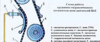
The camshaft is held against axial movement by a support flange. A driven sprocket is installed at the front end of the camshaft. The camshaft and auxiliary shafts are driven from the crankshaft drive sprocket by a double-row roller chain. The drive is equipped with a damper and a chain tensioner with a shoe. The flywheel
is installed at the rear end of the crankshaft and is attached to it with six bolts. The flywheel is cast iron, with a pressed-on gear ring, which is necessary for starting the engine with a starter. When assembling a new engine, the flywheel is balanced along with the crankshaft.
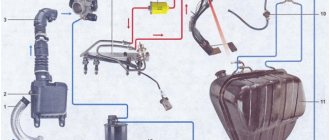
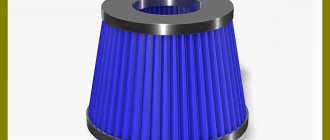
1 — crankshaft pulley; 2 - generator; 3 - coolant pump; 4 — thermostat; 5 - carburetor; 6 — air intake; 7 — thermostat; 8 — air filter housing; 9 — oil filler plug; 10 — cylinder head cover; 11 — ignition distributor; 12 — cylinder head; 13 — coolant temperature indicator sensor; 14 — cylinder block; 15 — oil separator for the crankcase ventilation system; 16 — oil pressure sensor; 17 - flywheel; 18 — fuel pump; 19 — camshaft drive cover; 20 — oil filter; 21 — engine sump
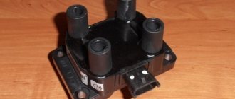
1 — crankshaft pulley; 2 — crankshaft position sensor; 3 — camshaft drive cover; 4 - generator; 5 — coolant pump; 6 — thermostat; 7 — chain tensioner; 8 — idle speed regulator; 9 — fuel rail; 10 — throttle position sensor; 11 — throttle body; 12 — receiver; 13 — fuel supply pipe; 14 — filler plug; 15 — fuel drain pipe; 16 — cylinder head cover; 17 — oil level indicator (dipstick); 18 — cylinder head; 19 — coolant temperature indicator sensor; 20 — cylinder block; 21 — oil pressure sensor; 22 - flywheel; 23 — ignition coil (module); 24 — engine support bracket; 25 — oil filter; 26 — engine sump
How to tighten the cylinder head of a VAZ 2107
This article will talk about how to replace the gasket and tighten the cylinder head of a VAZ 2107. In fact, it’s not difficult to do it yourself, although you’ll have to tinker a little. The head gasket is a small and cheap element, but it affects the operation of the entire internal combustion engine. And first, it’s worth finding out what symptoms of a damaged gasket may appear.
- Basic faults
- Start of work
- Removing the cylinder head of a VAZ 2107
- Gasket replacement and assembly
Camshaft tightening torque for VAZ 2107 injector
We replace the camshaft and install timing marks on the VAZ 2107 with our own hands
VAZ 2107 car owners are sometimes bothered by a knocking sound under the hood. There may be several reasons for this phenomenon. In this article we will look at one of them. Below you will learn how to replace the camshaft on a VAZ 2107, how to set timing marks so that the engine runs in tact.
Basic functions of the camshaft
The camshaft opens and closes the valves, allowing the fuel mixture into and out of the cylinder. There are cams on the camshaft. These are the protrusions that transmit torque to the levers. One arm of the rocker (lever) receives torque from the camshaft, the other transmits it to the valves. Thus, the valves open. When the cam rotates further, it stops acting on the rocker, and the springs return the valve to its original position, that is, it closes. The camshaft is driven by the action of the crankshaft. They are connected by a timing chain or belt. If we draw an analogy with a bicycle, then the crankshaft is the pedals, the camshaft is the rear wheel, and the timing chain is the same on a two-wheeler. While the crankshaft makes two revolutions, the camshaft makes only one.
How to understand that the camshaft needs to be changed?
You can determine a camshaft malfunction without opening the hood by two signs:
- knock;
- reduction in engine oil pressure.
The main reason for malfunctions in the camshaft is the appearance of gaps. They appear between the shaft bearing journals and the bed bearings on which the camshaft rests. The cracks are formed due to the fact that parts of the camshaft are worn away. Gaps cause the shaft to move in the vertical or horizontal axis. If the shaft play is 1 mm, then this affects the operation of the engine. Reasons for gaps:
- the camshaft was not replaced in a timely manner;
- do not change the oil on time;
- use of low-quality oil;
- the driver drives at low speeds, so little oil enters the timing belt and parts wear out faster.
The camshaft also needs to be changed if the oil channels in it are clogged. Before changing the part, look for any play, fracture, deformation or scuffing of the shaft.
How to choose quality parts
Buy a camshaft from a reliable and time-tested company, for example, PJSC Avtovaz. The packaging has a seal with a hologram. It shimmers in the light and features the company's logo. There is also a sticker with a barcode on the box. The item is packaged in blue translucent film. There is a stamp from the Quality Control department inside the package. Buy rockers together with adjusting bolts. There are new and old style levers. The holes in them differ in diameter and number of cuts. If you buy rockers and bolts separately, chances are they won't fit together.
Removing the camshaft
The engine must be cold when replacing the camshaft. You will need:
- New camshaft;
- Set of levers with bolts;
- Wrenches for 7, 8, 10, 13, 17 and 24;
- Small and large screwdriver;
- 3 spare lever springs;
- Rail;
- Valve cover gasket;
- Torque wrench
- Remove the air filter, separate the tip, cable and throttle linkage.
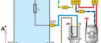
- If you have a carburetor engine, remove the fuel hose from the bracket; if you have an injection engine, disconnect the vacuum hose, air supply hose and remove the fuel filter from the bracket.
- Remove the cylinder block cover.
- Align the mark on the camshaft sprocket with the top dead center of the 4th cylinder. If you have a carburetor engine, you can turn the crankshaft with a special wrench. And if there is an injector, then you need to jack up the car, engage fourth gear and spin the rear wheel.
- Remove the gasket.
- Bend the camshaft sprocket washer with a chisel.
- Engage fourth gear to lock the crankshaft.
- Remove the tensioner.
- Unscrew the nut and remove the star. Tie the chain to the sprocket so that the links do not jump to other teeth.
- Unscrew the nuts and pull out the camshaft.
- Remove the rocker, bolts and springs.
Installing a new shaft
The new camshaft must be lubricated with engine oil before installation.
- Check the lever springs. If they are broken or bent, replace them.
- Screw the adjustment bolts into place.
- Install the springs, then attach the rocker to them.
- Now you can insert the camshaft with housing. Lubricate the levers, cams and journals of the camshaft with oil. Fit them on and tighten them with a torque wrench. The procedure is performed from the center to the edge. Tightening torque – 2 kgf*m.
The diagram for tightening the VAZ 2107 camshaft nuts is in the photo
Diagram of the camshaft nut tightening order
Checking the alignment of the timing marks
If you do not match the crankshaft and camshaft marks, the engine will not operate correctly. Setting timing marks on a VAZ 2107 injector is no different from the same procedure on carburetor engines. The mark on the crankshaft pulley should align with the mark on the front engine cover. And the point on the rim of the camshaft sprocket should be opposite the beacon on the bed.
Align the mark on the star with the protrusion
When you put on the sprocket, lock the camshaft so that it is stationary. Do not tighten the star nut all the way. Align the marks on the camshaft by turning the sprocket. The chain should remain in its original position, so throw the links until you reach the alignment of the mark and the ebb on the bed. Then use the wrench to move the crankshaft a quarter turn counterclockwise. Turn the crankshaft back so that the marks on it match. When the marks are aligned on both the crankshaft and the camshaft, tighten the nut on the camshaft sprocket with a torque wrench. Tightening torque – 5 kgf*m. Adjust the chain tension using the tensioner.
Tip to note
To avoid having to change the camshaft due to a malfunction, install a new shaft every 100 thousand km. Use high-quality oil, do not forget to change it on time and monitor its consumption. If the engine consumes more oil than necessary, the shafts will wear out faster.
Purpose and principle of operation
The camshaft is a metal rod on the axis of which eight cams are placed. These are parts that have an irregular shape. They rotate on the axis of the camshaft and are located opposite the inlet valves of the cylinders. Their rotation ensures stable combustion of the fuel mixture inside the cylinders. All these mechanisms are brought into precise synchronization.
Thanks to the proper operation of the shaft, a mixture of air and fuel is released into the cylinders in a timely manner, compression and release of exhaust gases occurs. On the Classic, the camshaft is driven by the fact that its gear rotates as a result of interaction with the crankshaft sprocket through a chain.
On the VAZ 2107, the camshaft is located at the top above the cylinder block. Thanks to this, it is available for self-replacement. This also makes it possible to easily adjust valve clearances.
To better understand the principle of operation of the camshaft, watch the video tutorial.
How to properly tighten the cylinder head bolts on a VAZ 2106: cylinder head tightening torque
Each car owner who is faced with repairing the cylinder head will have to put this element in place after completing the task. This procedure involves tightening the cylinder head bolts. If this is not done, the seal of the unit may be compromised. Below we will look at what torque of the VAZ 2106 block head is most important and what to consider when installing the device.
When is it necessary to puff?
How to tighten correctly?
Tools and materials
Comments and Reviews
When is it necessary to puff?
First, let's look at the cases in which it is necessary to tighten the bolts of the cylinder head of a VAZ 2106 car engine:
- If engine oil comes out from under the cylinder head. The problem indicates damage or natural wear to the head gasket. It is necessary to remove and replace the seal. The leak may also be due to loose cylinder head bolts. The presence of a problem is indicated by oil stains that appear at the junction of the head and the motor block.
- After repairing the power unit. If you removed the fastenings in a Niva or any other car and rebuilt the engine, then for successful assembly you should take into account the order of tightening and the diagram, as well as the tightening force of the screws.
- For prevention purposes. Experts recommend tightening the bolts on the cylinder head every 2-3 thousand kilometers. When the engine is operated under vibration conditions, this can cause the screws to loosen, so they must be periodically checked and tightened with proper force.
The Ilyich Garage channel has published a video that will help you understand the process of tightening the cylinder head bolts on the “six”.
How to tighten correctly?
You can tighten the bolts with the help of specialists or yourself. If you have never encountered the need to perform this task before, then below we will look at how tightly you should tighten the screws and in what sequence you should do it.
Be sure to strictly observe the tightening torque, since if the head bolts are overtightened, this will lead to cracks and damage to the cylinder head. If this happens, the car owner will have to carry out major repairs to the unit. The working surface of the hole, as well as the threaded connection of the screw, must be as clean as possible. A wire brush can be used to clean the cylinders. If during the task you find “blind” holes for the head screws, use a cleaning lubricant carefully. If the volume of the substance is greater than required, it will be difficult to install the pin all the way.
Before tightening, it is necessary to visually diagnose the condition of the bolts. If the fastening elements are damaged or worn out, their quality is generally low, then it is better not to tighten them with these screws; it is recommended to replace them with new ones.
It is recommended to lubricate the threads of new bolts with a small amount of engine oil or another type of lubricant.
Tools and materials
To tighten the cylinder head, prepare only one tool - a torque wrench, which will allow you to determine the tightening force of the screws. It is best to purchase a key in a specialized store or rent it at a service station, since this tool can only be used for tightening and tightening. Using a regular wrench will not allow you to determine how many kilograms the tightening force is.
When purchasing bolts, it is recommended to give preference to branded parts. Be sure to look at the threaded part - it must be intact, without damage or defects; if any, the fasteners are replaced.
Channel “Engine Repair! And interesting!” published a video that describes all the nuances of the stretching process.
Algorithm of actions
The order and strength required when pulling the cylinder head bolts is as follows:
- In accordance with the diagram below, tighten all bolts using a torque wrench. The tightening torque on the first round of tightening the fasteners will be about 3.5 - 4.1 kgf/m. First, the bolts are tightened, which are located in the center of the block head - top and bottom. After this, the two upper and lower fasteners are screwed in, installed on the side of the screws located in the center. Then the two outer bolts are tightened. Please note that you need to tighten the left pins first, and then the right ones. Screw number 11, located at the bottom left, does not need to be touched.
- This is the first stretch circle. At the second stage, the bolts are tightened in a similar order. Only the force with which the fastening elements are tensioned by the tool will be 10.5 - 11.5 kgf/m.
- At the third stage, the bolt is tensioned, which is marked with number 11 in the diagram. The tightening force of this screw should be 3.5 - 4.0 kgf/m.
Photo gallery
Photos of the tension diagram and process are shown below.
Video
User Sergey Samarsky made a video where he showed and described in detail all the nuances of the process of independently tightening the cylinder head screws of a VAZ 2106 engine.