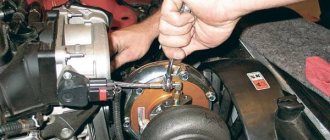
Recently, an engine tilter that I made specifically for repairing Volga engines was successfully tested.
You can hang the engine with everything attached to it, turn it and lock it in any convenient position. The design is thought out so that nothing interferes with disassembling the engine to the bare block. The paws are attached to the engine instead of the mounting brackets for the pillows.
The axis of rotation of the engine is located approximately at its geometric center. Due to this, the design turned out to be as compact as possible. Plus, the stand is collapsible, making it easier to store.
I think everything will be clear from the photographs.
The base is a frame made of 60mm channel. Uprights with support hinges at the top are screwed to the frame. The hinges are made of pipe and open on hinges. After installing the assembled engine with legs on the stand, the hinges are closed and secured with nuts.
To secure the engine in the desired position, a removable clamp is placed on one of the axles. It is enough to loosen it, turn the engine and tighten it.
I made a stopper on two wheels diagonally - a curved plate is bolted to the frame, clamping the wheel.
A pallet is attached to the bottom of the frame. It was bent from a sheet of galvanized roofing.
I can only say approximately the dimensions - I measured everything in place, placing an empty block on the choppers. The frame is approximately 60x80 cm, the height of the posts is 35 cm.
The materials are the most affordable. Channel 60, channel 50, pipe with diameters 36 and 28, two 8mm plates, wheels from trolleys. Tools - grinder, welding, drill, file.
Comments 25
The stand looks promising. Two questions. First: wouldn't it be better for me to add height to the posts (my height is 180 cm)? Second: how long are the channels on the brackets? If there are any other useful tips learned from the experience of using the tilter, I will be glad to use them. The engine needs to be repaired.
My height is about the same, the height of the stand is enough for me. The length of the channel is about 20 cm. All sizes turned out to be optimal - both compact and convenient. Only the mechanism for fixing the engine position has been altered - the clamp does not hold well. I welded a bicycle sprocket and a spring-loaded clamp.
Dear Gleb, to say that you are a handy and big-headed person would be an understatement. I am always amazed by such skillful people and, in addition, sharing their ideas and inventions, because in the bustle during the process, or greed, not everyone puts their brainchild on public display. Respect. What if we make a more powerful vertical stand, but one, not two, and accordingly make one lateral mount to the engine? Will three bolts of one mount support the entire engine and attachment? I don’t want to attach it to the output side of the crankshaft so that there is easy access to the oil seal packing. And if so, then this stand could be made more universal. What do you say to Gleb and the rest of your comrades? I'm interested in any opinion.
Engine tilter stand
Homemade stand tilter for disassembling and assembling engines.
I made an engine tilter; you can install the engine with everything attached to the device, turn it and lock it in the desired position. The device is made in such a way that nothing interferes with completely disassembling the engine down to the block.
Materials used:
- Channel - 60 mm.
- Channel - 50 mm.
- Pipes - 36 and 28 mm.
- Metal plates 8 mm - 2 pcs.
- Wheels from a cart.
- A piece of galvanized steel.
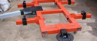
The homemade design is shown in the photo.
The axis of rotation of the engine is located at its geometric center.
The frame is made of 60 mm channel, racks with support hinges at the top are screwed to the frame. The hinges are made of pipes and open on hinges. After installing the assembled engine with legs on the stand, the hinges are closed and secured with nuts.
You can secure the engine in the desired position with a removable clamp; just loosen the clamp, turn the engine and tighten it.
On a pair of wheels diagonally, I made a stopper from a curved plate, which is bolted to the frame and clamps the wheel.
A tray made of galvanized roofing sheet is installed under the engine.
Dimensions: frame 600 x 800 mm, height of racks 350 mm.
Homemade author: Gleb. Minsk.
Review and cost
To transport motors, water-motor boats use carts, both individually produced to suit their needs, the design and weight of the motor, and industrially produced (for universal use), which can be purchased in stores selling water-motor equipment and boats.
Trolley for transporting outboard motor TM-2
The trolley is designed to carry a fuel tank with the engine; it has a collapsible design. The support for a stable position, the mount for a standard fuel tank, the handle with wheels are easily detachable. To install the motor on a boat, it must be removed from the cart and moved to the transom of the boat. The weight of the aluminum trolley is 8.7 kg, which is two times lighter than a trolley made of structural steel. Cost 6500 rubles.
Price - 6500 rubles.
Morlab trolley
This is a transformable trolley. The design is patented. The stand, support, and handle for transportation are folded, the assembled cart is very compact and allows you to take it with you to the boat. The weight of the trolley is 6 kg, which is ensured by the frame being made of a square aluminum profile. The special design and shape of the false transom allows you to transfer the motor from the cart to the transom of the boat without lifting the motor. Cost 7500 rubles.
Price - 7500 rubles.
Homemade engine tilter
Many car enthusiasts repair their car engines on the garage floor or on a workbench. This is always inconvenient, associated with constant lifting of weights, tilting a bulky cylinder block or cylinder head. All these factors lead to excessive fatigue of the car mechanic and a decrease in the quality of engine assembly. To make their work easier, craftsmen have developed many homemade tilter designs for the engine.
Options for homemade tilter designs
There really aren't many options. In the West, complex and bulky home-made structures are known, like a crane beam, almost with hydraulic drives.
In domestic conditions, car enthusiasts assemble the simplest structures from what is at hand. Of the homemade tilters for the engine, two-support and cantilever versions are known. The last design is the easiest to manufacture. Its characteristics are sufficient to carry out major repairs of almost any passenger car engine weighing from 150 to 250 kg.
Before starting to manufacture the unit, it is necessary to study in detail the existing samples of stands for engine repair. The sample is selected to suit the immediate needs of an amateur car mechanic. The availability of materials and dimensions for ease of work in a small garage are assessed. The permissible load weight is calculated in accordance with the type of engine that is to be repaired.
Based on the results of a study of existing structures, a sketch drawing of the most optimal version of a cantilever-type tilter was developed. Overall dimensions in the diagram are given in millimeters.
In the sketch, the designations D 60 and D 52 correspond to diameters of 60 and 52 mm.
Materials for production
Due to the fact that the engine tilter will have to work under severe conditions of physical stress associated with the weight of the engine, high demands are placed on materials.
The following materials are used for manufacturing:
- steel square profile 70 x 70 with a wall thickness of 3 mm, length 3 m;
- steel pipe with outer diameter 60 mm, inner diameter 53 mm, length 245 mm;
- steel pipe with outer diameter 47 mm, length 480 mm;
- steel channel with internal side width 70 mm, wall thickness 3-4 mm, length 280 mm;
- flange for bolted connection to the engine - 1 pc.
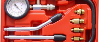
Tools and hardware for stand assembly
To connect the nodes of a metal structure made of a steel channel and a square profile, you will definitely need a welding machine that allows you to work with an electrode with a cross-section of at least 3-4 mm. In addition, for cutting you will need a grinding machine with a metal cutting disc with a diameter of 115-125 mm. To ensure bolted connections of prefabricated parts, you will need a drill with the ability to work with a drill with a diameter of up to 14-20 mm. M12 bolts are also required to assemble the structure.
You will also need a set of files to cut off burrs and uneven edges, and remove flaws in metal cutting. It wouldn't hurt to purchase some sandpaper to remove rust from the surface before painting.
Assembly of the engine tilter
The first step is to cut out the channel and square profile in accordance with the sketch. Next, a vertical post is made from the profile and welded to the square from the channel. Then the structure is reinforced with metal slopes, which can be made from scrap parts.
After this, a base is welded from a cut square profile - a tilter stand for engine repair. At the site of the bolted connection to the base of the vertical post, preparatory work is carried out, steel bushings are inserted and welded to strengthen the structure.
Then you should begin the final assembly of the engine tilter. The stand is connected to the stand by welding and M12 bolts.
A horizontal pipe with an outer diameter of 60 mm and an inner diameter of 52 mm is welded to the vertical stand. A horizontal axis is inserted into this part. It can be made of a steel pipe with a diameter of 47 mm with a welded flange for bolting the cylinder block or cylinder head.
Assembly
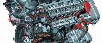
If the installation will need to serve various types of engines or simply be for all occasions, then it should be made universal. It should be taken into account that VAZ car engines differ significantly from BMW mechanisms in fastening methods. It may be necessary to create a stand for disassembling and assembling the KamAZ-740 engine or other large-sized engines.
A pair of channels with 10 mm holes is welded to the rotation plate. The pitch is 50 mm. Places for channels are marked in the area of the motor mounts. The center of gravity is precisely directed along the axis of rotation of the plate. This will make it possible to simply rotate the stand around its axis.
Using a manual hoist makes it possible to install the structure on wheels (they must be strong enough). This will make it easier to move the faulty part around the room. If necessary, it can be easily moved to the far corner. You should also attach a tray at the bottom, thanks to which the dirty waste from the engine will not spill on the floor. The existing pan below will make it possible to flush the engine.
Homemade engine stand (tilter).
Making a homemade tilter stand for mounting and repairing the engine.
Some garage craftsmen who like to repair their own car with their own hands disassemble the engine on a workbench, and some even on a stool or box. But even for small-capacity engines, the cylinder block weighs several tens of kg, even without a cylinder head, crankshaft and flywheel. And when making repairs on a table, turning it over is quite difficult and dangerous, because you can inadvertently press your fingers, and you have to do this several times. And when disassembling it on a stool or some kind of box, there is always a risk of dropping the unit on the floor or feet. I propose to get rid of the inconveniences described above and make a simple stand for securing and fixing the engine in 16 different positions, which will make disassembling and assembling the engine a pleasure.
The stand, which will be described in this article, is designed for all engines of the VAZ family, both rear-wheel drive classics and front-wheel drive cars. It is also suitable for some foreign cars, namely Italian engines.
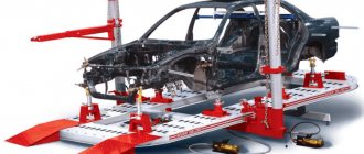
But if the mounting dimensions do not suit some motors of other machines, then you just need to make the motor mounts based on the dimensions of your particular unit, and the distance of 680 and 740 mm (see Figure 1) will also need to be changed based on the dimensions (length) your engine.
Most stands shown in various books, catalogs or the Internet have a cantilever motor mount (mounted to one side of the block) and only one stand. This design still causes some caution, and yet, based on the well-known proverb “one head is good, two are better,” it is still desirable to make a more reliable two-legged stand (with two stands, shown in Figure 1). Such a stand will be much more stable and reliable, and the price is just another profile pipe and another block mount.
Moreover, the double-sided fastening of the engine will make its installation much easier, and no hydraulic engine lift or several people will be required. Only two people of average build will be able to mount the engine on such a stand.
And at the moment when the special supports of the motor (see Figure 2) with their spikes 4 (axes) fall into the lower halves of the bearings 3 (they are shown in Figure 1), the engine is already suspended on the racks and is already quite stable. And if you also install the bearings in the desired operating position and tighten the covers with bolts 5, then the motor will already be securely fixed.
Flange 1 and rib 2 of the engine support (for Zhiguli) in a closer view.
Primary requirements
The main requirements for a stand for disassembling and assembling engines are versatility and ease of use.
It is also important how many levels of freedom are provided in the design, what tonnage the selected equipment should withstand
Currently, stores offer a wide range of options to choose from. You can assemble the structure yourself. This will save money and help you choose parameters in accordance with your wishes for personal ease of use.
A homemade installation must be durable and reliable. All metal elements are assembled by welding. In this case, it is better to seek help from a specialist. He will be able to qualitatively weld all the parts together. In this case, the safety of service personnel can be guaranteed while performing their activities.
How to make a car tipper
There are many motorists who prefer to repair their vehicles themselves when they break down. At the same time, minor damage can usually be easily repaired in a garage, but repairing a car body or suspension usually requires the use of special tools and sophisticated equipment. For example, a lift or tipper may be required.
Factory-made devices are quite expensive, so they are beyond the means of ordinary motorists. Despite the fact that tippers are used extremely rarely, they are indispensable when performing certain jobs.
There are numerous original designs of car tippers that you can create yourself at home.
They have different designs, but are designed to facilitate working conditions during serious repair work. At the same time, making the device does not take a lot of effort, time and money.
We will tell you how a regular tipper works and how to make it yourself?
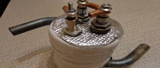
Shoe
This structural element is made of a metal sheet 3-4 mm thick and a metal rod with a diameter of 12 mm, which is welded to securely fix the jack. It is necessary to maintain the internal size without avoiding contractions. This will allow the shoe to move within the rack.
Rear beam
It can be made from a 32 mm corner with a length of 150 cm. You will need 4 such parts. They must be assembled into a square using clamps. A rod made of a metal square 26x21 mm, 35-36 cm long, is inserted inside one square. First, you need to drill holes for it and clean them. This unit must have a collapsible design.
Area
It requires a metal sheet 3-4 mm thick. The platform should have dimensions of 15x35 cm. The sides should be bent or a strip 20 mm wide should be welded to them, holes should be drilled in it for fastening the inserted board.
A rubber strip is attached to the board, and ribs are welded under the bottom of the platform to increase rigidity, as well as guides. Be sure to weld a strong jumper.
The dimensions of the platform may vary, but it is important to maintain the size between the guides.
The platform is placed on the top beam, and it should be easy to walk on it.
Rear node
This connecting structural element should be made of 3-4 mm sheet metal. It consists of two halves with a metal strip 3-4 mm thick welded between them around the perimeter. The front should be open. Don't forget to weld the jumper to the bottom of the rear connection assembly.
Rack
To create it you will need four 32 mm corners with a length of 154 cm and four 36 mm corners of the same length. A square is assembled from the corners and the joints are welded. When assembling, use clamps for convenience. After the corners are connected, you need to make a hole with a diameter of 26 mm. It should be located 31 mm from the edge.
Thus, 5 mm will remain for welding the metal rod in the inner part. After this, holes with a diameter of 13 mm should be made: one at a distance of 100 mm, the next after 80 mm and then after 190 mm. Accordingly, the dimensions 80 and 190 mm are repeated.
Purpose
Every driver wants a vehicle to be reliable in operation and serve for many years. But situations still happen when the main breakdown of the car is the engine. This is where you will need a stand for disassembling and assembling engines. There are different versions of it.
Such a stand is designed to significantly simplify the process of inspecting the unit, as well as troubleshooting, repair and depreciation. After removing the engine from the compartment, the unit is tightly and securely mounted on a special stand.