Electrical circuits
I propose in this topic to collect electrical circuit diagrams for FF3.
Electricians, diagnosticians, dealership employees and other teammates who have access to standard FF3 electrical equipment diagrams are kindly requested (if you want to help your teammates) to post the diagrams in this thread. Here are 20 diagrams for 2.0 PSh titanium, which were sent by snot 1) Heated windshield and rear window 2) Starting the internal combustion engine. Included is the 'keyless' car entry system 3) Starting the internal combustion engine. Not included Keyless Entry System 4) Electronic Engine Controls 5) Automatic Transmission 6) Speed Control 7) Steering Column Control Module (SCCM) ESD 9) ABS 10) Anti-Theft Alarm System 11) Body Control Module (BCM) 12 ) Battery charging system 13) Audio system 14) Tail lights 15) Exterior lighting 16) Instrument panel and lighting system 17) Turn signals and hazard warning lights 18) Horn 19) Instrument panel 20) Automatic temperature control
22) Scheme of standard xenon from Gonshchik
23) Complete set of electrical circuits for FF3
24) Signed VSM connectors from ANDREY1973
25) A complete set of electrical circuits for FF3 in good quality Schemes Connector catalog: https://scheme.red-ford.ru/connectorcatalog.pdf Pin catalog: https://scheme.red-ford.ru/pins.pdf Updated catalog pins: https://scheme.red-ford.ru/2019_Pigtail_Guide.pdf Thank you: Impa
Keep people scheme
I bought them on the Ford website. schemes for 2.0 PN titanium, but something similar will be for other variations of tricks.
https://www.ifolder.ru/26577850
Keep people scheme
I bought them on the Ford website. schemes for 2.0 PN titanium, but something similar will be for other variations of tricks. ifolder.ru/26577850
https://depositfiles.com/files/e750jd5ql
Can anyone tell me if this is the injector? There are some numbers 1E421 and 1E422.
How can you figure out what colors the wires are among these bourgeois abbreviations?
I found it on the Internet, maybe someone needs it
Important terminals: Terminal 15 is powered from the ignition switch. Current flows only when the ignition is on. The wire is usually green or green with colored stripes. Terminal 30 Battery voltage is always applied to this terminal. The wire is usually red or has colored stripes. Terminal 31 is connected to ground. Ground wires are usually black. In electrical diagrams, symbols consisting of a combination of letters and numbers are introduced for individual wires.
Example: 31S - ASZA/1.5 BK/RD 31 = terminal 31 = “ground” (-) S = electrical wire included additionally (not serial) AC = system (AC = lighting range adjustment) FOR = communication: 3 = wire number, A = branch designation 1.5 = 1.5 mm2 VK = main color (VK = black) /RD = marking color (RD = red)
Abbreviations for the colors of electrical wires on diagrams GN = green RD = red SR = silver WH = white VT = violet YE = yellow VC = black GY = gray BN = brown LG = light green BU = blue OG = orange
Source: https://ffclub.ru/topic/256431/
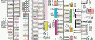
Block arrangement
This diagram will show the general location of all electronic control units in the Ford Focus 3.
p, blockquote 4,0,0,0,0 —>
Scheme
p, blockquote 5,0,0,0,0 —>
p, blockquote 6,0,0,0,0 —>
Description
p, blockquote 7,0,0,0,0 —>
| 1 | ABS electronic control unit |
| 2 | Electronic air conditioning control unit |
| 3 | Anti-theft alarm horn - on the right side of the luggage compartment |
| 4 | Audio interface control unit |
| 5 | Accumulator battery |
| 6 | Diagnostic connector (DLC) |
| 7 | DC/DC converter control unit |
| 8 | Driver's door electrical control unit |
| 9 | Left rear door electrical control unit |
| 10 | Passenger door electrical control unit |
| 11 | Right rear door electrical control unit |
| 12 | Electronic Engine Control Module (ECM) -behind the left wheel arch trim |
| 13 | Cooling fan motor control unit |
| 14 | Cooling system radiator damper control unit |
| 15 | Fuse/Relay Box, Engine Compartment 1 |
| 16 | Fuse/Relay Box, Engine Compartment 2 |
| 17 | Fuse/Relay Box, Instrument Panel |
| 18 | Fuse/Relay Box, Luggage Compartment - Left Side Luggage Compartment |
| 19 | Glow plug control unit - behind the left wheel arch trim |
| 20 | Headlight control unit |
| 21 | Heater Blower Motor Resistor - Next to the Blower Motor |
| 22 | Beep 1 |
| 23 | Beep 2 |
| 24 | Ignition switch control unit |
| 25 | Instrument cluster interface control unit |
| 26 | Instrument cluster control unit |
| 27 | Control unit for remote control of central locking and engine start |
| 28 | Lane tracking system control unit |
Ford Focus 3 has 3 main blocks with fuses and relays: in the cabin, under the hood and in the luggage compartment.
Electrical circuits
In the contents box there is a list of electrical circuits, then immediately circuit diagrams
When purchasing a book in PDF
1. You will be able to download the book immediately after payment.
2. The book will be downloaded in PDF format, and you can download it to any device.
1. All books are of ideal quality, since we work with publishers directly.
2. Electronic books are in no way inferior to paper books and are their complete analogue.
3. Our company has offices in Ukraine, Russia and Poland, you can always contact us at a specific address.
4. All payments on the site are maximally protected and are made using global payment systems.
Payment for goods and downloading of the book in electronic form (PDF format) is made on the website.
To do this, you need to find the book you are interested in and click on the “Buy” button. The price of the book is indicated on the button.
For convenience, the price on the website for residents of Russia, Belarus and Kazakhstan is presented in rubles.
For residents of Ukraine in hryvnias, and for all other countries - dollars.
After clicking on the “BUY” button, a payment window will open where you can select a payment system with which you can pay for the selected book using any bank card (Visa, MasterCard, MIR, etc.)
When you click on the “Pay by bank card” button, the Portmone payment system will open, which is the easiest way to make a payment.
In addition, the website offers four payment systems for payment:
- Yandex (payment from any bank cards, Yandex Money account, QIWI Wallet, terminals, etc.);
- Portmone (payment from any bank cards, Portmone account);
- PayPal (payment from any bank cards, PayPal account);
- WebMoney (payment from any bank cards, payment from WebMoney wallets).
What is included in the electrical circuit?
The electrical circuit of Ford Focus 1, 2, 3, 4, Ford Transit, Ford Scorpio cars includes many different components. The main components that power the electrical network are, as is known, the battery and the generator device. The ignition system is designed in such a way that the spark to ignite the combustible mixture is transmitted through high-voltage wires. Below you can find diagrams and designations of the main components.
Like any other car, Ford Mondeo 1, Focus 1, 2, 3, 4, restyling is equipped with a fuse box, the elements of which allow you to protect the car’s electrical equipment from power surges. But in addition to the main power supply, Focus 4, 3 or any other is also equipped with another unit in which relays are installed.
Electrical diagram of the block with relay
Relay designation
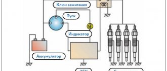
It will not be possible to start the engine without the ignition system, so we suggest that you familiarize yourself with the diagram of its connection and the designation of the main components.
Ignition system Ford Focus 1,2 3, 4
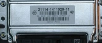
Also worth mentioning is the ECM - the electronic engine control system.
Engine control system and designation of main components and elements
An equally important point that any focus guide should be familiar with is the connection diagram for the generator device. As stated above, a lot depends on the functioning of this device, so you need to know about its connection in any case.
Payment via Yandex Cashier
After selecting payment via Yandex, the Yandex Cashier payment system will launch, where you need to select a convenient payment method (bank card, QIWI, Yandex Money account, etc.)
After specifying payment details and confirming payment, payment for the goods will occur.
If you have a bank card in a currency other than the ruble, then the money will be debited from the card at the rate of the Central Bank of Russia at the time of the purchase.
This payment method is optimal for residents of Russia, Kazakhstan and Belarus.
Official website of the Yandex Kassa payment system https://kassa.yandex.ru
Payment via Portmone
After selecting payment through Portmone, the payment system will launch, where you need to select the payment method: bank card or Portmone account.
The price in the Portmone payment system is converted into dollars at the exchange rate of the Central Bank of the country where you are located.
If you have a bank card in a currency other than the dollar, then the money will be debited from the card at the rate of the Central Bank of your country at the time of the purchase.
After specifying payment details and confirming payment, payment for the goods will occur.
Official website of the Portmone payment system https://www.portmone.com
Wiring diagram ford focus 2 restyling
For ease of searching within the page, a fragment of the diagram, links are provided below. Return to the top of the page, Ctrl+Home keys.
- Connection diagram for generator and engine start. Sheet 1
- Connection diagram for generator and engine start. Sheet 2
- Electronic engine management system. Sheet 1
- Electronic engine management system. Sheet 2
- Ignition system
- Connection diagram for injectors and cooling fan
- ABS/ESP control unit. Sheet 1
- ABS/ESP control unit. Sheet 2. Beginning of the adaptive lighting scheme
- Adaptive lighting. Sheet 2
- Adaptive lighting. Sheet 3
- Headlight unit with xenon. Sheet 1
- Headlight unit with xenon. Sheet 2
- Side light
- Automatic switching system
- Brake lights
- Direction indicators and hazard warning lights. Sheet 1
- Direction indicators and hazard warning lights. Sheet 2
- Mounting block in the engine compartment
- Mounting block fuses in the engine compartment
- Relay in the engine compartment mounting block
- Mounting block in the cabin
Payment via PayPal
After selecting payment via PayPal, the PayPal payment system will launch, where you need to select the payment method: bank card or PayPal account.
If you already have a PayPal account, then you need to log into it and make a payment.
If you do not have a PayPal account and you want to pay using a bank card via PayPal, you need to click on the “Create an Account” button - shown with an arrow in the picture.
PayPal will then prompt you to select your country and provide your credit card information.
After specifying the information required to make the payment, you must click on the “Pay Now” button.
Official website of the PayPal payment system https://www.paypal.com
Downloading a book
After successfully completing the payment (by any method) and returning to the KrutilVertel store from the payment system website, you will be taken to the successful payment page:
On this page you need to indicate your e-mail, where access to download the book will be sent.
If you are already registered on our website, then simply follow the link to your personal account.
The book you purchased will be in your personal account, from where you can always download it.
Please note that after making the payment, you need to return back from the payment system website to the KrutilVertel website.
If for some reason you did not return back to the site and closed the payment system tab with a message about the successful completion of the payment, please let us know - we will send you a letter indicating access to download the book.
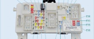
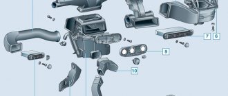
Blocks under the hood
Example of block arrangement
Mounting block
It is located on the left side of the engine compartment and is covered with a protective cover, on the back of which the current block diagram will be applied.
Photo - diagram
Fuse designation
| 7 | 40A ABS, ESP |
| 8 | 30A ESP |
| 9 | 30A Heated rear window 40A Fuse box in luggage compartment |
| 10 | 40A Heater motor |
| 11 | 30A Voltage Quality Module, Start-Stop System |
| 12 | 30A Engine control unit relay EGR valve |
| 13 | 30A Starter Relay |
| 14 | 40A Heated windshield (right side) 25A Rear window lift |
| 15 | 25A Cooling fan, Transmission control unit |
| 16 | 40A Heated windshield (left side) 20A Battery sensor |
| 17 | 20A Auxiliary heater |
| 18 | 20A Wiper |
| 19 | 5A ABS, ESP |
| 20 | 15A Horn |
| 21 | 5A Brake light switch |
| 22 | 15A Battery monitoring system 5A Parking assistant |
| 23 | 5A Relay Coils, Light Switch |
| 24 | 20A Rear socket 5A Heated windshield (right side) |
| 25 | 10A Electric mirrors |
| 26 | 15/20/25A Transmission control unit |
| 27 | 15A Air conditioning compressor clutch |
| 28 | 5A MAF Sensor, Rear Camera, Adaptive Cruise Control 10A Rear View Camera, Forward Collision Warning System |
| 29 | 20A Headlight washers 10A Rear view camera, collision warning system |
| 30 | 5A Engine control unit |
| 31 | 15A Intercooler Fan (1.6L Duratorq TDCi) |
| 32 | 10A Exhaust Gas Recirculation Valve, Swirl Control Valves, Heated Exhaust Gas Oxygen Sensor (Engine Management System), Electronic Fan Control Module Relay (Coil) |
| 33 | 10A Ignition Coils |
| 34 | 10A Injectors, Cooling system pump, canister purge valve |
| 35 | 5/15A Active radiator shutters, Heated fuel filter (diesel engines), Water in fuel sensor, engine control unit, ignition coils |
| 36 | 10A Engine control unit 5A Active radiator shutters |
| 37 | 5A ABS 15A Daytime running lights, headlight control unit 20A Additional socket on the instrument panel |
| 38 | 15A Engine control unit, gearbox control unit |
| 39 | 5A Headlight control unit 15A Electric driver's seat |
| 40 | 5A Power steering |
| 41 | 20A Body electronics unit |
| 42 | 15A Rear wiper |
| 43 | 15A Headlight range control, adaptive lighting |
| 44 | 5A Adaptive cruise control |
| 45 | 10A Heated windshield washer jets 15A Electric passenger seat |
| 46 | 25A Front power windows or Cooling system fan |
| 47 | 7.5A Heated mirrors |
| 48 | 15A Diesel fuel combustion product filter evaporator 5A Electric mirrors |
Additional sockets can also be supplied with fuses 24 and 37 at 20A.
Relay
| R1 | Intercooler fan |
| R2 | Sound signal |
| R3 | Diesel combustion product filter evaporator or 14-18: Heated windshield |
| R4 | Reserve |
| R5 | Rear wiper |
| R6 | Cooling fan |
| R7 | Heated windshield |
| R8 | Cooling fan |
| R9 | Headlight washers |
| R10 | Cooling Fan, Starter |
| R11 | A/C compressor clutch |
| R12 | Cooling fan |
| R13 | Heater motor |
| R14 | The engine control unit |
| R15 | Starter, Heated rear window |
| R16 | Ignition |
Power fuse block
It is made in the form of high power fuse links and is located in the battery cover.
Scheme
Purpose
- F1 (80A) Power steering control unit
- F2 (150A) Starter
- F3 (100A)
- F4 (50A) Multifunction control unit
- F5 (80A) Additional heater
- F6 (70A)
- F7 -
- F8 (50A) Cooling fan motor control unit
- F9 (50A) Multifunction control unit
- F10 (60A) Glow plug control unit
Problems when paying with bank cards
Sometimes difficulties may arise when paying with Visa/MasterCard bank cards. The most common of them:
- There is a restriction on the card for paying for online purchases
- A plastic card is not intended for making payments online.
- The plastic card is not activated for making payments online.
- There are not enough funds on the plastic card.
In order to solve these problems, you need to call or write to the technical support of the bank where you are served. Bank specialists will help you resolve them and make payments.
That's basically it. The entire process of paying for a book in PDF format on car repair on our website takes 1-2 minutes.
Source: https://krutilvertel.com/ford-focus-3-2010-glava20-jelektroshemy
Ford Focus 3 theft protection is a serious undertaking
Ford Focus is a regular visitor to installation shows. Among the reasons for the frequent appeal are the large number of cars of this model in the city, official statistics on thefts (they are often stolen) and word of mouth. The first surge of “Focus” activity was observed after an unsuccessful attempt to steal one of them belonging to our client, while the car itself was thoroughly vandalized. Owners often know as well as car thieves that there are weak points in the security of this particular model and turn to specialists for help.
This is not the first time the owner of the new 2013 Ford Focus 3 has contacted us - he once entrusted us with the protection of his old Focus. The previous car served its purpose and was sold, and we were tasked with equipping its successor with all the necessary means of protection. Requirements: inexpensive (corresponding to the class and cost of the car), but convenient and efficient.
Due to circumstances beyond our control, the installation was carried out in two stages. The client came to us for the first time to install a hood lock and immobilizer.
Ford Focus III 2011. Repair and operation manual
repair book
Auto repair manual for Ford Focus in electronic form. The manual will always be at hand during car maintenance and repair; to do this, just download it for free to your tablet or phone in pdf format.
Before using the car manual, check the year of manufacture and engine of the car.
Format: pdf
Size: 139.1 Mb
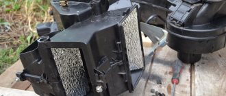
Block in the trunk
Located behind the casing or protective cover.
Photo - example
Scheme
Description
| 1 | 5A Relay Coils |
| 2 | 10A Car keyless system module |
| 3 | 5A Door handles in cars with a keyless entry system |
| 4 | 25A Door module (front left) (window lifter, central locking, electric folding mirrors, heated mirrors) |
| 5 | 25A Door module (front right) (window lifter, central locking, electric folding mirrors, heated mirrors) |
| 6 | 25A Door module (rear left) (window lifter) |
| 7 | 25A Door module (rear right) (window regulator) |
| 8 | 10A Europe: Anti-theft siren |
| 9 | 25A Power driver's seat |
| 10 | Power windows, '14-'18: Audio amplifier |
| 11 | 5A Vehicle Keyless System Module, 25A Power Passenger Seat |
| 12 | 10A Air Conditioning Module (with Start/Stop Module) |
| 13 | 5A Instrument cluster (with start and stop module) |
| 14 | 7.5A Infotainment system display, GPS module (with start/stop module) |
| 15 | 15A Audio system (with start and stop module) |
| 16 | — |
| 17 | — |
| 18 | — |
| 19 | — |
| 20 | — |
| 21 | — |
| 22 | — |
| 23 | 25A Audio Amplifier |
| 24 | 30A Heated rear window |
| 25 | 20A Socket in luggage compartment |
| 26 | 40A trailer module |
| 27 | — |
| 28 | 40A trailer module |
| 29 | 5A Monitoring system for blind areas, road marking monitoring system, Active City Stop system, rear view camera |
| 30 | 5A Parking assistance module |
| 31 | — |
| 32 | — |
| 33 | 15A Rear wiper relay |
| 34 | 15A Heated driver's seat |
| 35 | 15A Heated passenger seat |
| 36 | — |
| 37 | 5A Luke |
| 38 | — |
| 39 | — |
| 40 | — |
| 41 | 5A Extendable towing device |
| 42 | — |
| 43 | — |
| 44 | 10A Electric mirrors |
| 45 | 7.5A Heated mirrors |
| 46 | 5A Monitoring system for blind areas, road marking monitoring system, rear view camera (with engine start/stop system) |
| Relay | |
| R1 | Egnition lock |
| R2 | Heated rear window |
| R3 | Rear wiper |
| R4 | — |
| R5 | Anti-theft siren |
| R6 | Auxiliary relay |
Ford Focus III 2011. Repair and operation manual
Ford Focus repair book
Operation of any Ford Focus vehicle is impossible without knowledge of its structure, maintenance and repair features. It doesn’t matter who will carry out the necessary work - every driver is simply obliged to know the basic maintenance and troubleshooting procedures.
The Ford Focus repair book contains all the necessary information that will help the owner understand the structure of the car, teach how to properly care for the car, timely maintenance and proper repairs.
The Ford Focus repair manual is divided into chapters: Vehicle design (describes general information and vehicle specifications); Operating instructions (preparation for departure, recommendations for traffic safety); Malfunctions along the way (tips to help you in case of an unexpected breakdown on the road); Maintenance (detailed recommendations for all maintenance procedures); Repair instructions (engine, transmission, chassis, steering, brake system, and also includes assembly and disassembly work necessary during the repair of a Ford Focus); Electrical equipment (detailed manual for diagnosing and troubleshooting, separately describing the main units and providing detailed electrical diagrams of the Ford Focus).
Any of the Ford Focus repair procedures is given according to the principle from simple to complex: from the simplest maintenance operations, adjustments, replacement of parts, to global repairs with assembly and disassembly work.
All materials in the book are based on specific experience gained in the process of complete disassembly and reassembly of a Ford Focus by highly qualified auto mechanics.
The book “Ford Focus III 2011. Repair and Operation Manual” is necessary so that diagnostics and repairs of the Ford Focus can be done professionally and quickly, even by the owner of the car who still has little practical experience.
You can download the Ford Focus repair manual for free in pdf format . You just need to download it to your phone or tablet and you can use it in any situation on the road.
Errors in fuse box repair
Many motorists underestimate the importance of regularly inspecting fuses to ensure they are working properly. Homemade fuses are often used. Of course, there are situations when you urgently need to replace a burnt out element. Then there is a temptation to use a homemade or Chinese fuse. This is strongly not recommended as it may damage the original electrical system of the vehicle.
Advice! Often, jumpers or commonplace paper clips are used as a protective element. To avoid short circuits or costly damage inside your vehicle, we recommend avoiding this practice.
It is important to understand that during repairs you need to pay attention to the fuse rating. Let us explain with an example: if a burnt-out PCB responsible for a car charger or cigarette lighter had a rating of 2A, then the replacement should be made with a part with the same resistance value. Ignoring compliance with ratings can lead to more serious and systematic breakdowns.
Colored electrical diagrams FORD FOCUS 3 » Fuse diagrams, car electrical diagrams
Before starting installation or repair work, it is recommended to clarify the purpose of the wires using a tester and visual inspection.
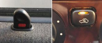
How to connect your phone to the radio On cars, the basic configuration does not have an AUX connector and a Bluetooth wireless communication module.
To expand the capabilities of the head equipment, it is necessary to replace the radio or modify the existing device by installing additional components, and installing an AUX port requires reprogramming the radio.
To connect your phone to the radio wirelessly, you need to purchase a Ford Focus 3 ignition switch pinout, placed in the USB port.
The product design contains a Bluetooth communication module, which transmits processed data through a connector. To get started, you need to install the signal converter into the USB plug, turn on the head unit, and then activate wireless communication on your phone or smartphone. The equipment allows you to listen to music, but is not intended for phone calls.
Site Map
Another connection method is to install a Bluetooth adapter model PT, which is connected via the power connector.
The device is mounted on the front panel, the volume level is adjusted using standard buttons on the steering wheel. Malfunctions and their solutions A common defect is the spontaneous shutdown of the radio after 10 minutes of operation with the engine turned off. After starting the engine and supplying voltage to the on-board network from the generator, the radio turns on, but then the situation repeats. The reason is an error in the Ford Focus 3 pinout of the ignition switch on the control unit, associated with prolonged use of the battery.
Instructions for resetting the BMS parameter responsible for battery life: Turn on the ignition, but you do not need to turn the crankshaft with the starter. Press the rear fog signal activation button 5 times successively. After this, press the Ford Focus 3 alarm ignition switch pinout button three times. The ignition system is designed in such a way that the spark to ignite the combustible mixture is transmitted through high-voltage wires.
Below you can find diagrams and designations of the main components.
Like any other car, Ford Mondeo 1, Focus 1, 2, 3, 4, restyling is equipped with a fuse box, the elements of which allow you to protect the car’s electrical equipment from power surges. But in addition to the main power supply, Focus 4, 3 or any other is also equipped with another unit in which relays are installed.
Electrical diagram of a block with a relayRelay designation Without an ignition system, it will not be possible to start the engine, so we suggest that you familiarize yourself with the diagram of its connection and the designation of the main components.
Engine control system and designation of main components and elements An equally important point that any focus guide should be familiar with is the connection diagram of the generator device.
As stated above, a lot depends on the functioning of this device, so be aware of its connection in any case. Generator connection diagram and designation of elements Common malfunctions Below are the main malfunctions that appear in the operation of the Ford Focus 3, 4, 2, 1 electronics: On these cars, the cables in the tailgate lid often break off.
Ford head unit connector pinout, 2 DIN 1 DIN diagram
Ford OEM radio pinout
Radio tape recorders installed on Ford cars have always been famous for their reliability, remarkable design and advanced functionality. The connection and pinout of the connectors of standard Ford radios is simple and logical - the connector of these car radios, until 2011, was similar to the connector of premium brand radios - it had a square shape, very ergonomically accommodating several sub-connectors for additional functionality, this connector is called Quadlock. The pinout of all quadlock connectors is similar, but Ford would not be Ford if it had not stood out among manufacturers and added its own special features and additional functions, for example “Anti Theft”, the task of which, as is not difficult to understand from the name, is to protect the radio from theft. And this is not the only innovation of quadlocks from Ford; they also have their own technology for communicating with the CAN - the car bus and a convenient, simplified system for retrofitting the radio with a Bluetooth function. But in cars since 2011 - in the 3rd generation (Ford Focus 3, and other models) the Quadlock connector was abandoned. The new connector has become slightly different in shape, now it is separated from the additional subconnectors. functionality, which are now scattered on the back wall of the radio.
There is probably no Ford car owner who would not be proud of the standard radio in his car. Owners do not often have to turn off and remove the radio, but in principle it is not difficult to do this. If you carefully study the instructions for the car, everything will immediately become clear and logical. In order to connect a Ford radio of any generation, you only need a radio pinout diagram and knowledge of the color indication of the car’s wires in order to understand which wire is responsible for what and what we connect to what. Let's look at both at once:
The diagram shows the pinout of the Ford 6000 CD radio and the color indication of the wiring of Ford cars. Such connectors are used on Ford cars of the last two generations, most often these are the 3rd and 4th generation of brand cars or other recent Ford cars. But we need to look at the connection diagrams and pinouts for car radios of all current generations of the Ford brand.
Pinout diagrams for radios of various Ford models
The article will discuss the radio pinout diagrams for the following Ford models: Focus 1 2 3 4 generations, Mondeo, Fusion, Transit, Kuga, Explorer, Escape, Fiesta, Eco - sport, S-max and other Ford models, both new and old , as well as radio tape recorders 6000 cd, 5000c, Ford - Sony and others.
Ford Focus 3, 4, Mondeo 3, 4, Transit, Kuga, Explorer, Fiesta, Eco-Sport and C-Max of the latest generations (after 2011)
Ford Focus 2, Mondeo, Transit, Kuga, Explorer, Fiesta, S-Max (generations up to 2011, Sony radio, 6000 CD)
Pinout diagrams for outdated radios of Ford models
Next, we will look at outdated and not very, but still relevant radio tape recorders:
Ford 5000C Sony
Ford 5000 RDS-EON
Ford Focus 1, Explorer 2G
Ford Galaxy (Sony)
Ford 3000 Traffic
Some old Ford radios with a CD changer
ISO - adapter for car radios of Ford models
And, if you want to connect a radio from Ford to a car of another brand, you will need an ISO - Euro plug. The adapter will allow you to connect the radio without resorting to cutting wires and soldering the connector, in general, without unnecessary work.
ISO connector for Ford
Adapter ISO-CARAV 12-040 for Ford
And so you can connect an ISO adapter to outdated Ford radio connectors
In the article we presented the pinout of the main current connectors for Ford radios. We hope that you have found among the information provided a pinout diagram for the connector you need. We wish you good luck in connecting! Meet us on the pages of our website!
Ford Focus 3 ignition switch pinout
If you diagnose electrical circuits, any short circuits are excluded, since this can contribute to the failure of the equipment as a whole. When replacing fuses, use only parts specified by the vehicle manufacturer.
If the elements are designed for higher current, they should not be used, like any other homemade fuses. To prevent a short circuit when replacing a fuse, it is prohibited to use any metal tools to dismantle and install them.
When the power unit is running, the battery cannot be disconnected, as this will damage the voltage regulator and other components of the electrical circuit. When diagnosing a Ford Focus 3 generator bridge ignition switch pinout, you cannot use a megohmmeter that is powered by more than 12 volts.
In principle, increased voltage is not recommended for diagnosing system components. If you are welding elements of a vehicle body, then to do this you need to disconnect the battery, as well as the generator device.
Source: https://inter-foto-press.ru/ford/focus/%D1%80%D0%B0%D1%81%D0%BF%D0%B8%D0%BD%D0%BE%D0%B2 %D0%BA%D0%B0-%D0%B7%D0%B0%D0%BC%D0%BA%D0%B0-%D0%B7%D0%B0%D0%B6%D0%B8%D0%B3 %D0%B0%D0%BD%D0%B8%D1%8F-%D1%84%D0%BE%D1%80%D0%B4-%D1%84%D0%BE%D0%BA%D1%83 .html
Replacing the PP in the car interior
The fuse box, which is located inside the car, is a kind of Achilles heel of the Ford Focus 3. If you think that your PP box inside the car has failed, then it’s time to carry out diagnostics. To do this, follow the instructions below:
- Open the hood of the car and disconnect the battery from the power supply. It is noteworthy that to replace or inspect fuses from any section, you need to remove the battery terminals.
- Under the glove box inside the car there is the unit itself. It is not easy to get to it, since it is located exactly under the glove compartment (popularly called the glove compartment).
- The block body is prudently secured with two clamps. To remove them, you need to pull them down at the same time. Once the fasteners are removed, you can remove the plastic cover.
- The fuses are located directly behind the cover. Following the diagram of their location, remove each one sequentially and inspect it. Be sure to replace burnt or faulty ones.
- Use the special pliers located there to remove all the fuses. After removing all the elements, you will see a cable harness. It must be carefully disconnected from the device.
- There are two more fastenings ahead, after which you can completely remove the block from the PP. This completes the preparatory steps. You can begin installing the new fuse box. Be sure to make sure that all previously disconnected harnesses are in their new place.
- After connecting, check the functionality by turning on the cigarette lighter, low and high beam headlights, car lights and others in turn. If everything works properly and there is no wiring smell, then you can close the lid.
The Ford Focus 3 fuse diagram will help you avoid confusion and check the required PPs. A car is a multifunctional system that uses dozens of fuses. When making repairs, carefully study the location of the parts, as well as their ratings. The average power of a cigarette lighter, for example, is 20A. This means that for replacement you need to select a spare part with exactly the same voltage rating.
Advice! If you doubt that you can handle electrical work for the first time, ask a more experienced friend for help. We assure you that replacing fuses the second time will seem like a simple task.
Electrical diagram of Ford Focus 3 restyling ETIS version - Ford Auto Service Samara
Electrical circuits
Below you can find diagrams and designations of the main components. Like any other car, Ford Mondeo 1, Focus 1, 2, 3, 4, restyling is equipped with a fuse box, the elements of which allow you to protect the car’s electrical equipment from power surges. But in addition to the main power supply, Focus 4, 3 or any other is also equipped with another unit in which relays are installed.
ELECTRICAL DIAGRAM FORD FOCUS - ELECTRICAL DIAGRAM
Connections of wiring and electrical equipment of a Ford Focus car. To enlarge the diagram, click on it. Wiper and windshield washer connection diagram
1 — ignition switch (lock); 2 — mounting block of relays and fuses; 3 - fuse 15 A; 4 — windshield wiper relay; 5 — windshield washer motor; 6 - combined steering column switch
Battery charging system connection diagram
1 — electronic transmission control unit; 2 — fuse mounting block; 3 - fuse 10 A; 4 - fuse 15 A; 5 - battery; 6 - starter; 7 - generator
Connection diagram of the brake system hydraulic drive system
1 — fuse mounting block; 2 — mounting block of fuses and relays; 3 — adjustable brake pedal switch; 4 — brake pedal motor reducer
Connection diagram of the ventilation, heating and air conditioning system
1, 9 — mounting block of fuses and relays; 2 - fuse 30 A; 3 — heater electric fan relay; 4 — heater electric fan motor; 5 — heater electric fan resistor; 6 — switch for operating modes of the electric heater fan; 7 — electronic engine and transmission control unit; 8 - instrument cluster
Ford engine starting system connection diagram
1, 5 - fuse 20 A; 2, 4 — mounting block of fuses and relays; 3 — ignition switch (lock); 6 — starter relay; 7 - battery; 8 - fuse link 150 A; 9 — starter; 10 - electronic engine and transmission control unit
Speed control system connection diagram
1 - fuse 20 A; 2 — fuse mounting block; 3 — ignition switch (lock); 4 — mounting block of fuses and relays; 5 - sensor; 6 - speed switch
1 — fuse mounting block; 2 - fuse 20 A; 3 — ignition switch (lock); 4 — mounting block of fuses and relays; 5 — electronic engine and transmission control unit; 6 — instrument cluster; 7 — clutch pedal position sensor; 8 — switch on the brake pedal; 9 - door lock control unit (central locking)