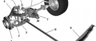
Rear suspension parts
1 – wheel hub; 2 – suspension arm mounting bracket; 3 – silent block; 4 – shock absorber casing; 5 – compression stroke buffer; 6 – casing cover; 7 – support washer; 8 – shock absorber cushions; 9 – spacer sleeve; 10 – shock absorber; 11 – rubber gasket; 12 – rear suspension spring; 13 – lever connector; 14 – lever of the rear suspension beam; 15 – shock absorber mounting bracket; 16 – lower spring support cup; 17 – rod; 18 – upper spring support cup.
Description of design
The rear suspension is with 12 coil springs and 10 double-acting hydraulic telescopic shock absorbers.
The main load-bearing element of the suspension is a beam consisting of trailing arms 14 and a connector 13, welded together through reinforcements. At the rear, brackets 15 with eyes for attaching shock absorbers 10 and flanges for attaching the rear wheel axles and brake shields are welded to the suspension arms. At the front, the levers 14 are equipped with welded bushings with silent blocks 3 pressed into them. A bolt passes through the central bushing of the silent block, connecting the lever to the bracket 2. Three welded bolts are provided to secure the bracket to the body spar.
The suspension spring 12 rests with its lower end on a cup welded to the shock absorber reservoir, and with its upper end, through a rubber gasket 11, on a support welded from the inside to the body arch.
The lower eye of the shock absorber is bolted to bracket 15 of the suspension arm, and its rod is secured to the upper support of the suspension spring through two rubber pads 8 (one at the bottom of the support, the other at the top) and a support washer 7 (under the nut).
The rear suspension springs are divided into two stiffness classes according to their length in the free state and under load: A (more rigid, “high”) and B (less rigid, “low”). Springs of the same class must be installed on the front and rear suspensions. But in exceptional cases, if class A springs are installed in the front suspension, class B springs can be installed in the rear suspension (but not vice versa!). The quality of the springs can be fully assessed by the performance of the suspension on the car. If the suspension often “breaks through” to the bump stops on uneven roads or sags under load, stiffer springs should be installed. When replacing springs, do not forget to check the serviceability of the shock absorbers - after all, it is the shock absorber-spring pair that largely determines the characteristics of the suspension.
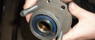
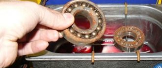
The hub has a double-row angular contact ball bearing, similar to the front wheel hub bearing, but smaller in size. The bearing fit on the axle is transitional (with slight interference or clearance). During operation, the bearing does not require adjustment or replenishment of lubricant. It is not allowed to eliminate the resulting play by tightening the nut; the bearing should be replaced. When dismantling the hub, the bearing is destroyed, so it is not recommended to disassemble the hub if the bearing is in good condition.
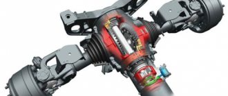
Suspension with virtual steering axis
This suspension is used on Volkswagen Phaeton passenger cars. When the front wheel is suspended on four arms, its rotation axis does not pass through the upper and lower hinges of the rotary strut, as is the case with known suspension designs, but through the intersection points of the extended axes of the upper and lower arms.
Rice. Suspension with a virtual axis of rotation of the wheel: 1…4 – directions of the longitudinal axes of the levers; R – wheel center; A – center of the wheel support surface; n – offset of the rotation axis relative to the center of the supporting surface; nv – offset of the turning axis relative to the center of the wheel; p – rolling shoulder; a – arm of action of disturbing forces; AS – point of intersection of the wheel turning axis with the road plane
Thus, the steering axis of the wheel is located, as it were, in free space and changes its location when the wheel is turned. Therefore, such a wheel rotation axis is called virtual. This design allows you to significantly bring the wheel’s turning axis closer to its middle plane. This has a positive effect on the values of the rolling arm and the arm of the disturbing forces, thereby improving the vehicle's handling and stability characteristics
Recommended: G12 Coolant: Red, Yellow and Green
The rear suspension beam consists of two trailing arms 15 (Fig. 17) and a connector 14, which are welded together through reinforcements. In the rear part, brackets 16 with eyes for attaching shock absorbers are welded to the suspension arms, as well as flanges 2, to which the rear wheel axles are bolted. At the front, the suspension arms have welded bushings 3 into which rubber-metal hinges 4 are pressed. A bolt passes through the hinge connecting the suspension arm to a stamped-welded bracket 5, which is attached to the body spar with welded bolts. The suspension spring 12 rests with one end on the shock absorber cup 1, and with the other through an insulating gasket 13 in a support welded to the inner arch (mudguard) of the body. On the shock absorber rod of the rear suspension, a compression stroke buffer 7 is installed, closed by a cover 8 with a casing 6, and shock absorber mounting parts - a spacer sleeve 11, cushions 10 and a support washer 9.
Rice. 17. Rear suspension parts
Shock absorber 8 (Fig. 18) of the rear suspension is hydraulic, telescopic, double-acting. It is attached with bolt 9 to the suspension trailing arm bracket. The upper mount of the shock absorber is pin-type: the tray is attached to the upper support 5 of the suspension spring through rubber pads 6, cup 2 and support washers 3. An insulating spacer 4 is installed between spring 1 and support 5. The lower part of the spring rests against cup 7. The details of the shock absorber are shown in Fig. 19.
Rice. 18. Shock absorber mounting
Hub 13 (see Fig. 18) has a double-row angular contact bearing 12, similar to the front wheel hub bearing, but smaller. Unlike the front wheel hub, where the inner bearing ring is installed on the hub with guaranteed interference, bearing 12 has a transitional fit. It is fixed in the hub with a locking ring 16, and on the axle 14 with a nut 15. The wheel axle is secured with its flange with bolts 10 to the flange of the rear suspension beam. The brake drum 11 is attached to the wheel hub with bolts and dowel pins 17.
Rice. 19. Rear suspension shock absorber parts
1 —
recoil valve nut;
2 —
recoil valve spring;
3 —
recoil valve plate;
4 —
washer;
5
— recoil valve discs;
6 —
throttle disk of the recoil valve;
7
- piston;
8 — piston ring; 9 — bypass valve plate; 10 —
bypass valve spring;
11
— restrictive plate;
12 —
spacer sleeve;
13 -
reservoir;
14 -
rod;
15 —
compression buffer support;
16
- nut;
17
— gasket;
18
— rod protective ring;
19 —
oil seal;
20 —
sealing ring of the tank;
21 —
rod guide bushing;
22 -
cylinder;
23 —
compression valve cage;
24 —
intake valve spring;
25 —
compression valve plate;
26 —
throttle disk of the compression valve;
27 —
compression valve discs;
28 — compression valve body; 29 —
rubber-metal hinge.
Rear suspension diagram for VAZ 2109
Problems with the rear suspension for the VAZ 2109 are not uncommon. Therefore, every car owner is obliged to know the structure of this unit, understand the circuit and understand where each element is located, how the rear suspension parts interact with each other.
Knowing the device and circuit, it will be much easier for you to identify the damaged element and carry out the repair yourself.
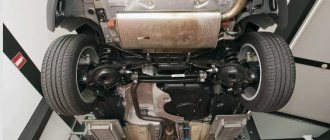
Bottom view
What causes damage to the body of the “nine”
ATTENTION! A completely simple way to reduce fuel consumption has been found! Don't believe me? An auto mechanic with 15 years of experience also didn’t believe it until he tried it. And now he saves 35,000 rubles a year on gasoline! Read more"
There is an opinion that Soviet cars are equipped with an “indestructible” body. It is impossible to say this one hundred percent, but it is also wrong to refute such a statement. Indeed, the body of the VAZ 2109, the diagram of which is presented in the article, is made to perfection, but over time, any quality will come to an end.
Almost all car bodies older than 5-7 years need repair. And there is nothing surprising about this. The living conditions of recent years, the huge amount of harmful substances, the general deterioration of the environment - all this cannot have a positive effect. Difficult, almost extreme, modern operating conditions also cause a lot of harm.
As a result, the state of the metal surface becomes deplorable, the internal combustion engine and parts are sent for disassembly, and instead of a worn-out but close-to-the-heart car, a new car takes its place. All this can be avoided if you know the features of the body layout, understand the intricacies and carry out preventive maintenance in a timely manner.
VAZ-2109 - what the rear suspension consists of
All of the above fully applies to the chassis.
Neither the front nor the rear suspensions are complex in design. Accordingly, repairs and troubleshooting should not cause any problems. In this article we will look at the design features of the rear suspension of the VAZ-2109. First, let's list its elements:
- hub;
- spring and its cups - lower and upper;
- lever mounting bracket;
- shock absorbers and their cushions;
- silent blocks;
- compression progress buffer;
- lever connector;
- rubber gasket;
- beam arm and connector;
- stock;
- spacer;
- support washer.
Generally speaking, the rear suspension of the “nine” is independent, torsion bar. Due to the not very high quality of domestic roads, especially in the outback, it is the chassis that bears the most serious load. Every hole or pothole that a wheel hits is a very noticeable blow to the suspension. You can understand that there are some problems here by hearing. In this case, you will hear an extraneous knock. It can be either deaf or voiced. Experienced professionals use it to make a “diagnosis”, and with very high accuracy. Accordingly, as soon as you hear that something is knocking in the suspension, you should immediately start looking for the problem.
Rear suspension device for VAZ 2109.
- central beam,
- trailing arms,
- mounting brackets,
- springs,
- hydraulic shock absorbers.
The central beam is the main element in the design of the rear axle of a car. The design is welded.
Springs and hydraulic shock absorbers are also of high importance in suspension. They are attached to the beam from below with bolts, and with their upper part to the car body through rubber-metal bushings.
Shock absorbers (double-acting) give smoothness and stability to the vehicle, and also dampen radial vibrations.
As for the rear suspension springs, they come in two stiffness classes: A - more rigid, “high” and B - less rigid, “low”. In this case, the rear springs must have the same stiffness as the front suspension springs. Although in some cases, it is allowed for class B springs in the rear suspension, and class A springs in the front suspension, but not vice versa!
In the case when the car’s suspension “breaks through” to the bump stops and (or) sags under load, it is recommended to install stiffer springs on the car, not forgetting to first check their performance.
But let's return to the main structural element of the rear suspension of the VAZ 2109 - the central beam.
According to the design of the car, flanges are welded to its side parts, to which, in turn, the hub is screwed. The hub has a sleeve bearing. This is a double-row angular contact bearing with a transitional fit on the axle. During vehicle operation, this wheel bearing does not require replenishment of lubrication or adjustment. By the way, if play occurs, the bearing should simply be replaced, but under no circumstances should you try to eliminate the play by tightening the nut. If the bearing does not play, then there is no need to remove the hub.
As for other malfunctions and possible repairs, I would like to note the following.
The chassis of a car is its basis, therefore, it is necessary to regularly (at least once every 6 months, and during intensive driving - once every 3 months) monitor its condition.
Diagram and designations
The rear suspension components are slightly smaller compared to the front. Because of this, the design can be called simpler. But this does not in any way reduce the degree of responsibility of you, as the driver, for the good condition of the unit.
Node diagram
Having familiarized yourself with the node diagram, you can move on to the elements that are indicated on it.
| Item number | What is |
| 1. | Wheel hub |
| 2. | suspension arm |
| 3. | Lever fixation bracket |
| 4. | Lever joint bushing (rubber) |
| 5. | Lever joint bushing (spacer) |
| 6. | Suspension arm fixing bolt |
| 7. | Car body bracket |
| 8. | Support washer for fastening the strut rod (shock absorber) |
| 9. | Upper spring support |
| 10. | Spacer |
| 11. | Rear suspension spring insulation gasket |
| 12. | Spring |
| 13. | Strut rod mounting pads |
| 14. | Compression Progress Buffer |
| 15. | Shock absorber rod |
| 16. | Shock absorber protection cover |
| 17. | Lower spring support cup |
| 18. | Shock absorber |
| 19. | Rear suspension arm connector |
| 20. | Hub axle |
| 21. | Cap |
| 22. | Rear wheel hub fixing nut |
| 23. | Sealing ring |
| 24. | Wheel bearing washer |
| 25. | Wheel bearing |
| 26. | Brake shield |
| 27. | Retaining ring |
| 28. | Dirt-reflecting element |
| 29. | Rear suspension arm flange |
| 30. | Rear suspension shock absorber bushing |
| 31. | Lever bracket with lugs for shock absorber mounting |
| 32. | Rear suspension arm joint, rubber-metal type |
Device Features
Having understood the diagram, you should separately talk about what the design of the rear suspension of the domestically produced VAZ 2109 is. Knowing all the features and nuances of the suspension elements used, you will know how to carry out further repairs, preventive maintenance, and what parts to buy for replacement old.
- The VAZ 2109 uses a torsion-link rear suspension design. The guiding device here is a pair of longitudinal arms, which are connected to each other using an elastic connector. Since the connector is shifted forward relative to the wheel axis, the kinematic properties of the rear suspension of the nine correspond to the features of an independent suspension on trailing arms.
- The independent movement of each wheel is ensured by twisting the amplifier with a U-shaped cross-section. This section is characterized by low torsional rigidity and high bending rigidity. This makes the structure quite reliable and durable.
- The trailing arms are made of pipes. They are welded to the connector through the rear suspension arm reinforcements, which makes it possible to create a single beam. It is hingedly suspended through a bracket on the car body.
- Each of the rear suspension arms in front is equipped with a bushing into which rubber-metal joints are pressed. They consist of a pair of bushings - rubber and metal.
- Through the spacer sleeve there is a bolt that connects the suspension arm and the stamped bracket, which is mounted to the body bracket using bolts, nuts and washers. A self-locking nut is screwed onto the mounting bolt.
- Brackets with lugs are welded to the back of the levers, which are used for mounting shock absorbers, and flanges are necessary for attaching the rear wheel hub and brake shield using bolts.
- The elastic components of the rear suspension include springs and a compression stroke buffer.
- The spring is made of spring steel with a round cross-section. It is installed on the shock absorber and rested with its lower part on the cup. The upper part rests on a support, which is welded to the inner arch of the car body. The lower spring support cup is welded to the shock absorber. A rubber insulation gasket is installed between the upper support and the spring.
- Rear suspension springs are divided into two classes, depending on the control load along the length - A and B. Class A is marked in yellow, applied to the outer side of the middle coils. Class B has a green designation.
- The compression stroke buffer is made of polyurethane. It is mounted on the shock absorber rod inside the spring. From above, the buffer rests against the cover of the protection casing, but when it is put into operation, it rests on a support.
- The buffer support is pressed onto the top of the shock absorber reservoir.
- The buffer has annular grooves on the outer surface that determine the location of deformation.
- The protection casing provides protection from mechanical damage and contamination of the rod and compression stroke buffer. The casing is made of corrugated rubber, which allows you to change the length when the suspension is operating. There is a ring groove at the top inside the casing. They serve to enter the spent part of the steel cover. At the bottom, the casing is quite elastic, which allows it to be pressed against the spring support cup.
- The rear wheel axle is mounted to the lever flange using 4 mounting bolts. The same bolts are used to secure the brake shield.
- The hub rotates on an axis on a double-row ball bearing. The hub is mounted to the axle using a nut and thrust washer. The nut is installed on the axle by crimping its collar into the groove of the axle.
- The bearing is mounted in the hub using a retaining ring. The bearing is closed and contains almost permanent lubrication.
- The inside of the hub is sealed with a pair of dirt-reflecting rings. One of the rings is welded to the hub, and the second to the axle flange. A labyrinthine seal is formed between them.
- The outer cavity of the hub is closed by a cap. There is an O-ring between the cap and the hub.
- During operation of the VAZ 2109, the hub bearing is not adjustable and is not lubricated. The wheel disc is mounted to the hub using 4 mounting bolts.
- The shock absorbers on the rear suspension of the nine are hydraulic telescopic double-acting.
- The lower eye shock absorber is installed on the lower arm bracket using a bolt and a self-locking nut.
- The upper fastener of the shock absorber is pin-type - the rod is mounted to the upper spring support through a pair of rubber pads and a support washer. There is a spacer between the protection casing cover and the washer.
The design of the rear suspension cannot be called simple, since there are many elements that interact with each other. If this effective interaction is lost, the car begins to behave unstable and requires repair or replacement of certain components.
We recommend: Ignition switch: device, purpose, operation, repair
It is not difficult to understand the diagram and structure of the rear suspension of the VAZ 2109 car. This will allow you to significantly save on repairs, avoiding visits to service stations, and also develop your own skills in independently repairing your own car.
Malfunctions of the rear suspension of the VAZ 2109.
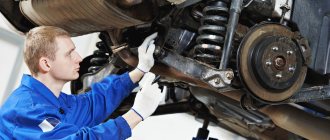
For high-quality suspension diagnostics, it is best to go to a service station, where specialists at special stands will diagnose the condition of your car and, if necessary, eliminate existing problems.
Although, in order to identify and eliminate some suspension faults, it is not necessary to be a qualified specialist. Here are some “talking” examples of visual diagnostics.
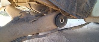
- Oily smudges under the car in the area of the rear suspension parts are a consequence of wear on the cuffs and shock absorber rod mirror.
- A knocking noise when driving usually indicates wear or loosening of the components.
- Strong impacts accompanied by a loud sound while driving on an uneven road indicate a loss of stiffness in the springs as a result of metal fatigue.
- Driving the car while moving to the side may indicate that the rubber-metal hinges attaching the beam to the side members are worn out.
By the way, a good test of shock absorbers is to simply press on the trunk of the car. If, with great force applied to the latter, the car sank and returned to its original position, without swaying, then the shock absorbers and springs are in working condition. If not, then there can be a lot of reasons for this: the seals, the rod are worn out, the valve mechanism, fluoroplastic bushing, etc. are faulty. Repairing the shock absorber helps in such cases, but not for long. It is advisable to replace such units with new ones and only in pairs.
If you find an error, please select a piece of text and press Ctrl+Enter.