03/23/2021 9,773 Audi
Author: Ivan Baranov
Using a vehicle's electrical circuit helps many car owners in diagnosing and identifying malfunctions in the operation of the on-board network. The electrical circuit diagram of the Audi 80 B4 can significantly simplify the troubleshooting procedure, so every car enthusiast should understand such a circuit. You can learn more about what systems make up the electrical circuit and how to determine the malfunction yourself from this article.
[Hide]
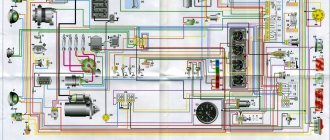
Audi 80 wiring diagram - electrical diagram
audi80 wiring glitch
The plus is usually made in red.
Home Forum Model range of Audi 80/90///A6 C4 cars. wiring diagram B3. I even have it in...
When checking, you need to turn the key in the lock to position 1, and then connect the multimeter probes or lamp contacts in turn to the terminals of the holders. To check, prepare a tester or test light.
Fuses and relays Audi 80 B4. Completely or partially discharged battery. This problem may be caused by oxidation of the contacts on the plug or connector.
Another option is to diagnose a particular section of the circuit for a short circuit.
Why do fuses burn?
A frequent candidate for replacement is the cigarette lighter fuse. It is located in a block located in the engine compartment and is additionally responsible for the operation of the audio system, on-board computer, interior and trunk lighting, and illumination of the mirror in the visor. Connecting a powerful compressor to inflate tires, an inverter or other equipment with high current consumption to the cigarette lighter often leads to the failure of the fuse. It is not recommended to replace it with elements of a different rating, as this may lead to electrical wiring failure. And its repair is much more expensive than the cost of the fuse.
Installing high power lamps can also cause a fuse to blow. Also, powerful lamps get very hot, which negatively affects the reflector and glass (especially if they are made of plastic). As a result of heating, the plastic glass of the headlight unit begins to transmit light worse, which negatively affects the operation of the headlights. Constantly failing fuses can cause the head light to completely disappear, making the machine impossible to operate. The maximum permitted wattage of light bulbs is indicated in the owner's manual and on the vehicle's headlights.
Independent, unqualified intervention in the on-board electrical system of a car is also a fairly common cause of failure of electrical equipment.
Exceeding the rated load on fuses, poor-quality insulation - all this can easily cause them to burn out. It is not recommended to replace burned-out elements with wires, coins, or install new ones of a higher denomination - this can lead to a fire in the electrical wiring.
Features of the package
The domestic auto industry has accustomed car enthusiasts to spartan conditions - a “working car” was the best configuration after purchase.
And when foreign cars began to be imported into our country, car enthusiasts discovered previously unknown facets of the car:
- It can be equipped with various power units;
- Have different equipment, including power steering and automatic transmission;
- Have numerous comfort features.
Power units
Cars arrived in our country with impressive mileage. However, thanks to the European service, the cars were in excellent condition, and the price was affordable.
Among the fitted Audi models, there were several power units included in the configuration:
- injection gasoline class “E” (from German Einspritzung);
- classic carburetor class “S” engine;
- diesel “D” (from German diesel);
- turbodiesel “TD” (from German turbodiesel);
- diesel version of the engine with turbocharging and direct injection “TDI” (from German: Turbocharged Direct Injection).
In addition, the engines had different injection systems:
- the KE-Motronic system was installed on the first releases;
- for subsequent ones - KE-Jetronic.
For reference: each of the engines had its own technical features. In particular, the electrical wiring of the Audi 80 on diesel engines differed from the gasoline versions. And among those running on gasoline, there were also differences, for example, the electronically controlled injection system was modified with each modernization.
Transmission
The types of transmissions also deserve special consideration:
- Classical mechanics;
- Automatic transmission.
The owners did not have any complaints about the manual transmissions. But automatic transmissions were difficult to maintain, primarily due to the presence of electronic components:
- Sensors and wiring;
- Electronic "brains".
For reference: the automatic transmission on the Audi 80 had protection modes - if the sensor failed, the automatic transmission switched to a gentle operating mode. After replacing the faulty sensor, the control unit had to be rebooted. But it was impossible to do this with your own hands - the “brains” can only be rebooted at a service station using diagnostic equipment.
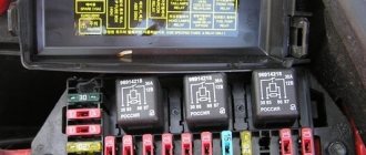
This unit is located in the rear of the engine compartment.
p, blockquote 11,1,0,0,0 —>
p, blockquote 12,0,0,0,0 —>
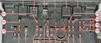
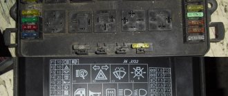
On the removed cover (7) of the central switch, a short form (6) shows the possible location of the relays and fuses. There are also small plastic pliers for disconnecting fuses. Inside the central switch, various relays (1), diagnostic plugs (2), fuses 1–21 (3), and additional fuses 23–32 (4) are visible. Next are four spare fuses (5).
p, blockquote 13,0,0,0,0 —>
p, blockquote 14,0,0,0,0 —>
Scheme
Table for Audi 80, 90 models up to 1989
p, blockquote 15,0,0,0,0 —>
| № | Elements of the protected circuit |
| 1 | 15A Fog lamps for headlights and rear lights |
| 2 | 15A Hazard Light Interrupter |
| 3 | 25A Horn, brake light |
| 4 | 15A Interior lamps, luggage compartment lamp, Audi 80 90 cigarette lighter fuse, sun visor mirror lamp, on-board computer, radio |
| 5 | 30A Engine Cooling Fan |
| 6 | 5A Lamps for side and parking lights of the right rear lamp |
| 7 | 5A Side light and parking light lamps of the left rear light |
| 8 | 10A Main beam lamp of the right headlight, control lamp for turning on the main beam headlights |
| 9 | 10A Left headlight high beam lamp |
| 10 | 10A Low beam lamp, right headlight |
| 11 | 10A Low beam lamp for left headlight |
| 12 | 15A Instrument cluster, reverse lamps, on-board computer, self-diagnosis system unit, Electronic control unit for the anti-lock brake system, Electronic differential lock control unit |
| 13 | 15A Fuel pump. |
| 14 | 5A License plate, engine compartment and glove box lamps, instrument cluster lamps |
| 15 | 25A Windshield wiper motor, engine cooling fan, electronic air conditioning control unit, turn signal lamps |
| 16 | 30A Heated rear window, heated rear view mirrors |
| 17 | 30A Electric motor of the fan (supercharger) of the interior ventilation system |
| 18 | 5A Electric rear view mirrors |
| 19 | 10A Central locking |
| 20 | 30A Switch (first stage) engine cooling fan, Electronic fan control unit when the engine is running |
| 21 | 25A Rear cigarette lighter |
| 22 | — |
| 23 | 30A Motors for adjusting the driver's seat position, driver's seat position memory unit |
| 24 | 10A Electronic control unit for the KE-Jetronic or Motronic system |
| 25 | 30A Seat heaters |
| 26 | — |
| 27 | — |
| 28 | 15A Electronic control unit for Motronic system |
| 29 | 5A Reserve |
p, blockquote 16,0,0,1,0 —>
| Number | Name |
| I | Fog light relay |
| II | Engine cooling fan relay |
| (high speed) | |
| III | Cooling fan relay |
| engine when the engine is not running | |
| IV | — |
| V | Unloading relay |
| VI | Air conditioner relay |
| VII | Horn relay |
| VIII | Automatic transmission relay |
| IX | Windshield wiper and washer intermittent relay |
List for Audi 80, 90 models from 1989
1. Fog lights, rear fog lights 15 2. Hazard warning lights 15 3. Horn, heated seats 30 4. Clock, trunk light, vanity mirror, reading light, socket/cigarette lighter, trip computer, full automatic air conditioning, radio, auto-check system (Auto-Check-System) 15 5. Second stage cooling fan speed 30 6. Right tail light, front side light 5 7. Left rear side light, front side light 5 8. Right high beam, high beam indicator lights 10 9. Left high beam headlight 10 10. Right low beam, right headlight leveling motor 10 11. Left low beam, left left headlight leveling motor 10 12. Instrument cluster, reversing light, Auto-Check system -System), automatic transmission, differential lock, on-board computer, control system, speed control, interior lighting lamp with off delay, electronic thermal switch, operation of the cooling system fan after stopping the engine 15 13. Fuel pump 15 14. License plate lamp, lighting instruments, engine compartment lighting, glove compartment lighting, automatic air conditioning 5 15. Turn indicators, windshield wipers, windshield washer pump, heated windshield washer nozzles, cooling system fan (control unit for turning on the cooling fan after stopping the engine), air conditioning 25 16 Heated rear window, heated external rear view mirrors 30 17. Fan, automatic air conditioning 30 18. Electrically adjusted external rear view mirrors, rear window washer (station wagon) 5 15 19. Central locking system, heated door paint mechanism cylinders, alarm 10 20. First stage of the cooling system fan, turning on the fan after stopping the engine 30 21. Self-diagnosis / connecting a diagnostic tool 10 22. Free -
Features of electrical equipment
The electrical circuit of the Audi 80 b3 includes many components and devices. In order to make it easier to navigate the diagram, they are conditionally divided into several systems. Let's consider the main ones:
- Engine fuel supply system;
- Ignition system;
- A special block in which all relay elements are installed, as well as fuses;
- System for adjusting side mirrors (rotation);
- A device that regulates the automatic raising of windows;
- The display panel on which the sensors are located. They are activated when the vehicle starts operating or when errors occur in its operation;
- Optical system (fog lights, interior lighting, turn signals, alarm);
- Cooling system (both the internal parts of the car and its interior - fan).
The electrical circuit of the Audi 80 b4 has some features. Let's look at the main ones:
- All devices and instruments are connected to each other using a single-wire connection (that is, using one wire);
- Weight on any device is always indicated by a minus. Audi 80 b3 is no exception. This wire is also connected to the car body (to its ground);
- The plus is marked in red in the electrical circuit and inside the car. Thanks to this, it is easier to diagnose the machine, as well as repair it;
- When the battery is activated (when the ignition is turned on), voltage begins to be supplied to the device. This means that before starting repairs, you should deactivate (disconnect) the battery. Otherwise, the wire may receive an electric shock;
- For each electrical unit, the pinout has a block with wires.
Quite often, a car has problems with fog lights, power windows, ignition or the fuel supply system (mono-injection). These are the most problematic areas of the machine.
To make it easier to subsequently diagnose faults in these systems, and then repair mechanical breakdowns, we will analyze their important features of electrical equipment.
Audi 80 b3 87 sf wiring diagram
#1 BangeR
- Audi Fans
- 15 messages
- Car: Audi 80 S, 1987, B3., SF., silver wind))
So, basically, I explained the topic in the title.. I found the diagram https://nwac.ru/forum. here, but it turned out that this is not suitable.. I want to give the machine to a knowledgeable person to revive it, but he needs a color wiring diagram. nid help . Google is not my friend, it showed me here
and a whole heap of kopek and nine-kopeck manuals. I'm sad .
Maybe someone has a thread about something similar?
- Top
#2 HOOCH
- City: St. Petersburg
- Car: Opel Kadett 1.3NB (was wounded in the heart, put it down); VW Passat 1.9TD (was stolen. uh-eh), AUDI 80 B4 ABT/AKPP - spatial body shifter
