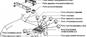
The relay is designed to inform pedestrians and other drivers about a change in traffic or vehicle maneuver. Depending on the modification of the car, it is located in the engine compartment of the car, or under the dashboard in the cabin.
Turn signal malfunctions - symptoms
- The absence of flicker is one of the obvious and frequent signs of device failure.
- No shutdown when turning the steering wheel.
- Very frequent blinking (often the cause may be a burnt-out lamp, or the power of the lamp does not correspond to the rating)
- Annoying clicking sound.
- Turn indicator dimly lit.
- Lights up but doesn't blink.
- Sticking.
- The hazard warning button is faulty.
To eliminate the causes of the turn signal malfunction, it is necessary to check and, if necessary, replace the VAZ turn signal relay.
Where is the VAZ turn signal relay located and how to replace it
The relay is designed to inform pedestrians and other drivers about a change in traffic or vehicle maneuver.
Depending on the modification of the car, it is located in the engine compartment of the car, or under the dashboard in the cabin. Turn signal malfunctions - symptoms
- The absence of flicker is one of the obvious and frequent signs of device failure.
- No shutdown when turning the steering wheel.
- Very frequent blinking (often the cause may be a burnt-out lamp, or the power of the lamp does not correspond to the rating)
- Annoying clicking sound.
- Turn indicator dimly lit.
- Lights up but doesn't blink.
- Sticking.
- The hazard warning button is faulty.
To eliminate the causes of the turn signal malfunction, it is necessary to check and, if necessary, replace the VAZ turn signal relay.
Symptoms of a faulty turn relay
Turn signals, as well as the relay that ensures their correct operation, make it possible to minimize the risks of
road traffic accidents when performing any maneuvers. That is why it is necessary to constantly maintain them in good condition and promptly eliminate any malfunctions.
The failure of the turn relay may be indicated by the following symptoms, which can actually be identified even without experience and diagnostic work:
- The turn signals do not blink, but stay on continuously. This indicates a breakdown of the electromagnet, which is stuck in one of two positions. Most likely, the relay may need to be replaced;
- The turn signal lamps flicker too quickly or, on the contrary, too slowly. This problem may be caused by incorrectly selected power of the light sources, however, it does not hurt to check the functionality of the relay;
- The turn signals don't work at all. It is quite possible that the cause of the breakdown is a burnt-out light bulb, a broken electrical contact, or a failed fuse. But if all these parts work normally, the problem lies in the turn relay.
Finding out that the device is not working is not difficult at all. If you do not hear characteristic clicks when you turn on the turn signals, then most likely the relay has failed and requires urgent replacement.
Location in the car
There are two types of location of turn signals in the classic VAZ family of cars, depending on the modification:
Let's start disassembling
- Early modification models
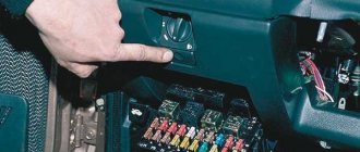
To get to the relay, you need to remove the plug by unscrewing the bolt on the dashboard.
We pull the entire panel towards us, move the sensor panel a little to the side so that we can get to the relay.
- The contacts approach the relay from below.
- Disconnect the contacts.
- We remove the old device and install the new one.
- We put the dashboard back, sliding it into the side grooves.
- Screw in the bolt.
We check the turn signals for flickering and characteristic clicks. The frequency of contact closure should be approximately 1 time per second.
The technology is very simple. The main difficulty here is accessibility to the relay. The space under the panel of these models is small, getting there is problematic.
- Later models
- Remove the screws from the steering column switch housing. We remove the casing elements.
- Unscrew the mounting bolt.
- We take out the devices on the electrical wiring inside the cabin.
- We replace the old relay with a new one.
- Screw it back. We put the covers in place.
Important: it is recommended to replace the relay itself or the mounting block as an assembly, given that the wiring often burns out and restoring the contacts is quite problematic.
When replacing any of the above relays, special attention should be paid to contact insulation. Insulation is performed using hollow mass braiding. To tie the wires, use a special strip clamp.
Video “Budget option for repairing a steering column switch”
The video below presents an inexpensive option for repairing the steering column switch in a Peugeot car (the author of the video is the EzjikOnline channel).
The cause of non-functioning electrical equipment in the car (for example, fuel pump, heated seats, heated windows, power windows, etc.) may be a faulty relay. Let's look at a simple way to test a car relay for functionality with your own hands.
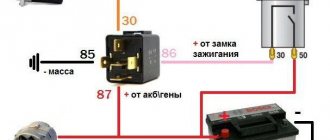
Connection diagram for 4 and 5 contact relays:
To check the relay you need (all relay contacts are labeled, and the power contacts usually have a yellowish tint):
- Apply 12 V voltage (for example, from a battery) to the terminals of the relay coil winding (control contacts 85 and 86).
- Measure the resistance (multimeter in ohmmeter mode) between the power terminals (30 and 87).
If the relay is working, then when voltage is applied there will be a click and the resistance will become close to zero (infinitesimal). Otherwise, the relay is faulty and must be replaced.
Feature of checking a 5-pin relay : contacts 30 and 88 must be closed, and when voltage is applied to the control contacts (85 and 86) they must open. Otherwise the relay is faulty.
The relay testing process is also presented in the video:
Let us remind you that another cause of electrical equipment malfunction in the car may be a broken wiring or short circuit. You can also determine the cause using a multimeter.
Key words: universal article
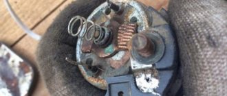
Transition from an electromagnetic-thermal relay to an electronic one.
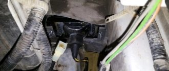
This “barrel” is located under the dashboard of a car. This is an electromagnetic thermal relay. Due to short-term operation (1-2 months), it is recommended to replace it with an electronic one. After this time, it begins to burn or shorts out.
The following are the steps to replace it:
- disconnect the contact terminals;
- We mark each wire with a marker, or use paint to highlight it in different colors;
- contact No. 1 of the electronic relay is connected to the wire with the x sign;
- Contact No. 2 of the electronic relay is connected to the wire marked L;
- contact No. 3 of the electronic relay is connected to the wire marked P;
- Contact No. 4 is ground, we connect it to a separate wire.
All this work must be carried out when using heat shrink.
The replacement of incandescent lamps with LEDs in direction indicators is gaining great popularity due to the fact that incandescent lamps are much inferior to LED lamps in terms of service life and light output.
Source: korchim.ru
Reasons for failure
As a rule, frequent relay breakdowns are explained by the low quality of components, both supplied from the factory and those still alive “cooperatives”. You can only combat this by choosing carefully or having a handful of other replacement parts. Repair is impractical due to the cheap cost, although there are examples of restoration “for fun.” The only difficulty is access to the place where the Niva turn signal relay is located; changing it is a matter of 2 minutes.
Another reason that can kill the breaker is increased voltage in the on-board network as a result of failure of the generator components and the voltage relay regulator. A short circuit is also possible. In any case, the circuit is examined, starting with a simple one - the state of the fuses .
Symptoms
The symptoms of the malfunction have characteristic features and are distinguishable from a burnt-out incandescent lamp or circuit damage. So, if the problem is in the relay, then the driver will see one of the following manifestations when turning on the turn switch:
- The indicator lamp does not light up, the turn signals are extinguished; The indicator on the dashboard and the turn signals are constantly on; There is an uncharacteristic crackling sound (clicking) when the relay operates; There is a change in the pace of functioning within a short time; Different response frequency compared to alarm.
Replacement method
To carry out operations you will need:
- Key head set to “10” (preferably with a ratchet mechanism); Plastic puller or similar device; Pliers; Phillips screwdriver.
Before replacing the Niva turn signal relay begins, disconnect the negative terminal from the battery. Access to the element being replaced is provided by removing the dashboard.
- 1. Take a screwdriver and release the instrument from the two self-tapping screws.
Breaker relay malfunctions
Malfunctions in the operation of the turn signal or low/high beam relays in the VAZ 2106 are quite rare. These mechanisms are quite reliable, but, being part of the overall electrical circuit of the car, they are not immune to problems such as overvoltage, breakdown, etc. In fact, the products are non-repairable - it is almost impossible to eliminate damage to the coil or contacts qualitatively. In other words, if a defect or malfunction is detected, the mechanisms are simply replaced with similar ones, selecting them by catalog number:
- for the turn signal relay - 231.3747-10(11) or 23.3747-10(11);
- for the lighting breaker relay - 113.3747-10(11) or 90.3747-10(11).
VAZ turn signal relay - do-it-yourself diagnostics and replacement
Turn signals are perhaps a very important part of any vehicle. Carrying out maneuvers on the road becomes quite a dangerous task if the turn signals do not work. The VAZ 2107 turn signal and hazard warning relay is responsible for the correct operation of the direction indicators. This device is used on all cars of the classic family. Let's consider why a turn signal relay is needed, how is a relay malfunction determined and how is it replaced?
What are turn signal relays for?
A turn signal relay, also called a breaker relay, ensures that the turn signals operate correctly. Unlike other lighting devices, turn signals operate intermittently, that is, they blink. This ensures additional attention from others to the vehicle driver’s intention to perform a maneuver: change lanes, make a turn, etc.
The intermittent operation of the direction indicators is ensured by the breaker relay. It closes and opens the electrical circuit, causing the turn signal lamps to flash, attracting the attention of others. Also, the breaker relay additionally ensures the creation of an audible click, which reminds the driver of the car that the turn signal switch is on. And the last function of the turn signal relay is the operation of the hazard warning lights, so in modern cars the operation of the turn signals and emergency lights is provided by one relay.
The absence of blinking of the direction indicators is equivalent to their malfunction, so a breakdown of the relay will not allow the driver to pass the inspection. Also, incorrect operation of turn signals is regarded as a failure to comply with traffic regulations to warn other drivers about the maneuver and can lead to a fine from the traffic police in the amount of 500 rubles.
Purpose of the turn signal and hazard warning relays
Everyone knows that direction indicators and hazard warning lights blink during operation. This is necessary in order to attract the attention of other traffic participants. The flickering of lamps cannot be confused with any other signal supplied by lighting devices. A small device called a turn signal relay . In addition to the blinking of the turn signals, the relay provides another function - creating the necessary sound signal (click), which indicates that the turn signals are in operation.
The Zhiguli used two types of relays, which differ both in their design and in their operating principle.
- The first type is electromagnetic type relay, which is mounted in the engine compartment of the car. The basis for the operation of the electromagnetic thermal relay is a special nichrome string, which, when heated and cooled, closes and opens the direction indicator circuit. These types of relays were used on early models of the “classic” family: VAZ 2101-2102 and VAZ 2103.
- The second type of relay began to be used on VAZ 2106 and higher vehicles. It is an electronic circuit built on semiconductor circuit elements. In addition to semiconductors, the relay also includes an electromagnet, which performs the functions of closing and opening. The frequency of operation of the electromagnet (or flickering of lamps) is achieved using a “key”, or a special electronic circuit.
Languages
We manufacture turn relays 12V-233747 (“Zhiguli”), and also carry out repairs. The product is an analogue of the direction indicator breaker 23.3747 “Avtopribor”, Vladimir.
Supply voltage, V
VAZ 1111, 2104, 2105, 2106, 2107, 21213, IZH 2126, 2715
The light signaling system of VAZ cars of the old model range uses several types of electronic relay-interrupters for direction indicators and hazard warning lights, relays 23.3747, 231.3747, 49.3747 or 491.3747.
Electronic relays 23.3747, 231.3747 direction indicators and hazard warning lights.
On VAZ-2106, 2107 cars produced before 1985, a relay 23.3747 assembled on integrated circuits is installed. Relay 23.3747 is mounted under the instrument panel on the wall of the air supply box. If the turn signal lamps are faulty, or there is a burnout or break in the lamp circuit, then the breaker relay ensures that the indicator lamp on the instrument panel is constantly lit.
Electrical diagram of relay 23.3747 direction indicators and hazard warning lights.
Electrical diagram for switching on relay 23.3747 direction indicators and hazard warning lights.
Since 1985, the VAZ-2107 has been equipped with a relay-breaker 231.374, made on the basis of discrete elements. Both relay interrupters have the same technical characteristics. They ensure blinking of turn signal lamps with a frequency of 60-120 cycles per minute at a rated load of 92 W, ambient temperature from minus 20 to plus 50 degrees and a voltage of 10.8-15 Volts.
Diagnostics of malfunction of the direction indicator relay VAZ 2107
If one day the turn signals stopped working. It's time to check what happened and, if possible, replace the faulty part of the circuit. Malfunctions of the turn signal relay can be recognized by several signs:
- The turn signals light up but do not flicker . This directly indicates a breakdown of the relay, or rather, its electromagnetic part. In this case, the electromagnet has closed in one of the positions and cannot return to its original state.
- The turn signals blink too quickly or too slowly . This can happen, but not only due to the fault of the turn signal relay. Sometimes the flickering speed of lamps can change if the turn signals use lamps that are not of the same power as those specified by the manufacturer. However, it wouldn't hurt to install a new relay as a test.
- The turn signals don't work at all . This means that the turn signal lamps and the lamp on the dashboard do not blink and there are no corresponding relay clicks. However, as in the second case, the malfunction does not always concern the turn signal relay. Sometimes the reason is a faulty hazard warning button.
Relay for turning on the direction indicators VAZ 2108, 2109, 21099
The intermittent mode of direction indicators (turn signals) on VAZ 2108, 21081, 21083, 2109, 21091, 21093, 21099 vehicles is provided by a breaker relay.
The following provides complete information on the turn signal breaker relay for VAZ 2108, 2109, 21099 cars and their modifications.
What is the turn signal relay for VAZ 2108, 2109, 21099 cars?
Relay-breaker for direction indicators of VAZ 2108, 2109, 21099 cars, electronic. It has three conclusions. Voltage is supplied to pin “49” from block Ш3/pin 2 of the mounting block, voltage output is from pin 49a of the relay (at Ш3/3), “ground” is pin “31”.
Details about connecting the turn signal relay in the diagram:
Connection diagram for direction indicators on VAZ 2108, 2109, 21099 cars
Where is the turn signal relay installed on VAZ 2108, 2109, 21099 cars
The turn signal and hazard warning relay is installed in the mounting block. In blocks 17.3722 and 2114 this is relay K2.
Mounting block 2108-17.3722
How does the turn signal relay work for VAZ 2108, 2109, 21099
In contrast to electromechanical relays, which are widely used in the electrical equipment of VAZ 2108, 2109, 21099 cars, the turn signal and hazard warning relay is electronic (the contacts in it close and open under the influence of an electromagnetic field).
The blinking frequency of the direction indicator lamps and the warning lamp in the instrument panel is set by the breaker relay 90±30 cycles per minute. When a lamp burns out, the blinking frequency doubles.
Turn signal relay malfunctions
The main malfunctions of the turn signal relay: oxidation of the relay contacts, burnout of the electronic filling as a result of a short circuit. Oxidized relay contacts can be cleaned by removing and inserting it into the mounting block several times. If there are problems with the electronics (the turn signals do not work or are constantly on without blinking), then we replace the relay with a new one or a known good one.
Applicability of the turn signal relay on VAZ 2108, 2109, 21099 vehicles
In the electrical equipment systems of VAZ 2108, 21081, 21083, 2109, 21091, 21093, 21099 vehicles, three-contact turn signal and hazard warning relay relays are used: 43.3747, 491.3747, 493.3747 and similar ones from different manufacturers.
On VAZ 21083, 21093, 21099 cars with an injection engine and a Europanel (panel 2114), the direction indicators are turned on via a relay for monitoring the health of the lamps in the mounting block.
Notes and additions
Twokarburators VK - More information on the topic in our VKontakte group, on Facebook Twokarburators FS , in Odnoklassniki - Twokarburators OK and in Yandex Zen - Twokarburators DZ
More articles on electrical equipment of VAZ 2108, 2109, 21099 cars
— Mounting block 2114
— Connecting blocks for mounting block 17.3722
— Ignition relay 2108, 2109, 21099
— Relays and fuses ECM VAZ 21083, 21093, 21099
— Connection diagram for tachometer VAZ 2108, 2109, 21099
— Relay for low beam and headlights VAZ 2108, 2109, 21099
— Wires for headlights VAZ 2108, 2109, 21099
— Pinout of hazard warning switch wires VAZ 2108, 2109, 21099
Replacing turn signal and hazard warning relays (+ Video)
After detecting any of the listed malfunctions, the turn signal relay must be replaced. Depending on the modification (carburetor or injector), the location of the breaker relay may differ noticeably. Carburetor VAZ 2107 vehicles require installation of the relay behind the dashboard in the vehicle interior. However, starting with an injection engine, the relay can be located in a mounting block in the engine compartment.
In order to remove the relay located in the mounting block, you just need to pry it up and pull it up. After this, a new element is installed in its place.
In the case of a relay located behind the panel, things are much more complicated. Before removing the relay, you must pry the dashboard using a screwdriver and remove it. If the length of the wires allows, you can pull it a certain distance, but if they are too short, it is recommended to pull out the plugs and unscrew the speedometer drive cable. Set the panel aside and disconnect the contact wires from the relay. Now unscrew the ground from the breaker and remove it. Install a new one in place of the old relay and insert the contact wires into it. After this, assemble the dashboard and install it in its original place. This completes the replacement of the turn signal relay.
Where is the turn signal relay on the VAZ 2114: location, replacement and repair
Current traffic rules require drivers to notify other road users before performing any maneuver by turning on the appropriate turn signal. A special relay-breaker for the turn signals, emergency lights and headlights is responsible for the proper operation of these warning lamps.
This device must operate without interruption, providing timely warning to other drivers about a change in direction of the vehicle, and if problems arise, they must be corrected immediately.
Design and operation of turn signal relay interrupters
The breaker relay, or as it is usually called, the turn relay, is designed to turn on the turn signals in a flashing mode, which more effectively attracts the attention of road users, informing them about the upcoming vehicle maneuver.
In addition, the flashing light signal of the direction indicators in all lights of the car - an emergency signal indicates an emergency situation with the vehicle and warns road users of the need for precautionary measures. The breaker relay is used in conjunction with the direction indicator switch, hazard warning switch and direction indicator lights. For optimal perception of the light signal, the blinking frequency of the direction indicator lights should be 60...120 min -1.
Automotive turn relays come in two types - thermionic and electronic. Currently, electronic relays are gradually replacing their thermionic counterparts, since they are more reliable, although they are not without some disadvantages (for example, they create radio interference).
The operation of thermionic interrupters is based on the property of some conductors to greatly elongate when heated, caused by the passage of electric current through them. Let's consider the design of such a breaker using the example of the RS57 turn signal breaker relay, which in the recent past was widely used on domestic cars of various brands.
The thermionic breaker RS57 (Fig. 1) has a core 13 made of electrical iron with a winding 15 placed on it, two armatures (main 7 and additional 12), two pairs of contacts 8 and 10, a nichrome string 5 and an additional resistance 6. The entire mechanism is mounted on textolite base 2 and covered with an aluminum casing 3. Three terminals B, SL and CL are connected to the base.
Rice. 1. Relay-interrupter RS57: 1 – contact clamps; 2 – textolite base; 3 – aluminum casing; 4 – adjusting screw; 5 – nichrome string; 6 – additional resistance; 7 – anchor; 8 and 10 – contacts; 9 – bracket; 11 – emphasis; 12 – additional anchor; 13 – core; 14 – return spring; 15 – winding
The turn signal breaker works as follows. When the turn signal switch is turned on, the current from terminal B passes through the core, armature, string, additional resistance, winding to the SL terminal and further to the turn signal lamps and control lamps. At this time, the lamps burn with incomplete heat, since an additional resistance of 6.7 ohms is included in the circuit.
When current passes, the string heats up and lengthens. The current passing through the winding creates a magnetic field in the core, and the core tends to attract the armature. After the string has lengthened, the armature contact will connect to the stationary contact and the resistance will be disconnected from the circuit. The lamps will burn at full intensity. As soon as the string cools down, the armature moves away from the core, the contacts open and the resistance is included in the lamp circuit.
The blinking frequency (1...2 s -1) is adjusted with a screw located on the base of the breaker on the outside. When screwing in the screw, the voltage of the string increases, and this, in turn, speeds up the opening of the contacts and increases the blinking frequency of the lamps. When the screw is unscrewed, the flashing frequency of the lamps decreases.
The disadvantage of such interrupter relays is the inconsistency of the length of the nichrome string, which stretches over time, and the interrupter needs to be adjusted. In the cold season, the nichrome string of the breaker also changes in length, which affects the frequency of blinking of the direction indicator lamps. In addition, when one of the turn signal lamps burns out, the load on the other lamps increases sharply, which can lead to their premature failure.
For these reasons, modern cars are equipped with more reliable and stably operating electronic turn signal relays, the electrical and wiring diagrams of which are given below.
The electrical circuit for switching on the RS950-P breaker relay in GAZ-2410, GAZ-3102 and GAZ-3129 cars is shown in Fig. 2, installation diagram - in Fig. 3.
Rice. 2. Connection diagram for the RS950-P relay-interrupter in GAZ cars: 1 – RS950-P relay-interrupter; 2 – side repeaters; 3 – direction indicator switch; 4 – alarm switch; 5 – hazard warning lamp; 6, 7 – 6A fuses; 8 – ignition switch; 9 – ammeter; 10 – battery; 11 – rear direction indicators; 12 – front direction indicators; 13 – direction indicator lamp; 14 – trailer direction indicator lamp; R1 – MLT resistor 2.7 kOhm; R2 – MLT resistor 1.3 kOhm; R3 – MLT resistor 10 kOhm; R4 – MLT resistor 7.5 kOhm; R5 – MLT resistor 1.8 kOhm; R6 – 820 Ohm MLT resistor; R7 – MLT resistor 1.5 kOhm; R8, R10 – MLT resistors at 240 Ohms; R9 – 120 Ohm MLT resistor; R11, R14 – 10 Ohm MLT resistors; R12, R16 – MLT resistors 1 kOhm; R13, R15 – 910 Ohm MLT resistors; C1, C2 – capacitors K73-17-250V at 0.68 μF; D1 and D2 – KDS 111B diodes; D3 – diode KD 209A; T1 – transistor KT 315V; T2 – transistor KT 209K; T3 – transistor KT 3102B; T4 and T5 – transistors KT 816G; K – executive relay; K1, K2, K3 – coils with reed switches KEM-2
Problems associated with the operation of turn signals on a VAZ 2114: the main reasons
The main reason why the turn signals stop working or do not work correctly is a breakdown of the VAZ 2114 turn signal relay. However, there are situations that should lead one to believe that the problems are caused by problems with other elements.
- a burnt out/failure of one or more light bulbs will make itself known by excessively rapid blinking when the turn signal is turned on;
- problems with the switch, contacts or wiring should be looked for if the turn lamps do not work when turned on, and the hazard warning lights function properly;
- oxidation of the wires of the contact group directly in the headlight or on the approaches to it is manifested by unstable operation of the turn signals.
Before you begin repairs, you should identify the real cause and only then begin to eliminate it. It is important to know where the turn relay is located on the VAZ 2114, since replacing this particular device in most cases solves the problem.
Signs of a malfunctioning turn signal relay on a VAZ 2114
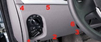
To understand what turn signal malfunctions car owners encounter, let’s look at their electrical circuit diagram.
The mounting block where the direction indicator relays on the VAZ 2114 are located is marked with the number 2. A chip with wires is connected to it from the power source. It should be noted that when the engine is turned off, the battery serves as the power source. As soon as the engine and generator start, the latter takes on the role of a source of electricity. In the mounting block, through relays and buses, the electric current is distributed into separate circuits. The turn signal relay is connected:
- With a switch (4), with which the driver turns on the indicator lights when performing the next maneuver;
- With a dashboard (7), on which indicator lights indicate that the turn signals are on or off;
- With ignition switch - positive contact. This is done so that the warning lights do not come on when the ignition is turned off.
- With another lever switch (8). It is with this switch that the driver turns on the turn signals. It is located under the steering column in the form of a small lever;
- Through switches, the relay is connected to signal lamps (1,5,6).
The electrical diagram image will help you find faults in the electrical circuit.
Damage to the electrical circuit of turn signals and emergency lights
Turn signals, like any other component of the car, periodically fail. For example, one of the system lights flashes quickly. The reason lies in a burnt out light bulb. You need to buy a new one and put it in its place.
The turn signal turns off randomly
Knowing where the VAZ 2114 turn relay is located, you can easily fix this problem. Open the relay and fuse box in the engine compartment, remove the relay and check it with a multimeter. Most often, the damage is hidden in this part. You can try to clean the contact legs with sandpaper and insert the relay into place. If the problem is not solved, then change it. The relay cannot be repaired, but is also inexpensive. Therefore, it is necessary to buy a new relay and replace it in the mounting block.
Turn signal lights are dim
The reason should be sought in the mass.
The ground outlet is located near the headlights. The front ones should be found on the body under the hood, the rear ones - behind the trunk trim. Cleaning the ground contacts and tightening the nut can improve the brightness of the light. If the turn signals do not turn on on only one side, there may be a break in the wiring; you need to ring the wires and try to find a break. If there is no break, check the contact pads of the connector. Practice shows that complete failure of turn signals occurs due to a faulty hazard warning button. And this is just understandable. If you look at the electrical diagram, you will notice that wires coming from the relay are connected to the hazard warning button, and the button itself is connected to the dashboard, lever switch, and through these elements to the lamps. So it turns out that a failed button completely disconnects the network. Therefore, in the event of a complete failure of the turn signals, you should first replace the emergency signal button.
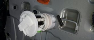
Turn signal relay VAZ 2114: where is it located
The VAZ 2114 turn signal relay is an electronic element that is located in the mounting block. Such a relay (usually an electromagnetic type) is responsible for the uninterrupted operation of the direction indicators, as well as for the blinking of the turn signals when the emergency lights are on. The device has several contacts at once, which makes it possible to control various electrical circuits.
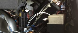
To find the turn signal relay under the hood of a VAZ 2114, you need to pay attention to the block located on the driver’s side almost under the windshield. Such a block is a dark-colored box, inside of which all kinds of relays and fuses are located. Among them you need to find a device marked K2. This will be the turn signal relay.
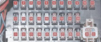
Where is the VAZ 2114 turn signal relay located?
If you are looking for where the turn signal relay is located on a VAZ 2114, everything is quite simple here. You just need to open the hood of the test car. Next, immediately under the windshield on the driver’s side, look for a dark-colored box (block) inside which there are actually various fuses and relays, and the VAZ 2114 turn relay itself is marked K2. The location is shown in the picture:
Symptoms of a problem
As we have already found out, most cases of malfunction of indicator systems are caused by an electromagnetic device, which is marked K2. However, malfunctions of the system as a whole can be caused by its other elements. For example, if when you turn on the turn signals, the flickering of the light bulbs is excessively rapid, this may indicate one or more burnt out or failed light bulbs. Or, for example, a situation where the hazard warning lights are working properly, but the turn signals do not signal - a possible reason may be related to a faulty switch, contacts or wiring. The reason for unstable operation is often not only the relay itself, but also the oxidation of the contact group of wires, both in the headlight and on the way to it. In other words, if you detect incorrect operation of an intermittent light signal, or its complete absence, do not rush to change the relay, sort out and analyze all the elements that can affect the operation of the system (light bulbs, wiring, switches, contacts).
How to replace the turn signal relay on a VAZ 2114
A sign that the relay should be changed is a situation where the emergency stop signals and turn signals fail at the same time.
Replacing the device is quite simple. To do this, perform the following steps sequentially:
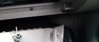
- The hood opens.
- Under it you should find the mounting block in which the relay is located (on the right directly above the driver's shock absorber strut).
- The mounting block opens (you can remove the protective cover by unlatching the two side latches).
- In order to easily remove the relay marked K2 (turn signal relay) from the mounting block, it is better to use plastic tweezers specially designed for this purpose (it lies in the block itself).
- After this, a new one is installed in place of the failed turn signal relay. It is placed in the seat so that the metal contacts (3 pieces) are inserted into the socket.
- After installing the new relay in the mounting block, you need to check whether the turn signals are working in the desired mode. If everything is in order, you can close the block cover and close the hood.
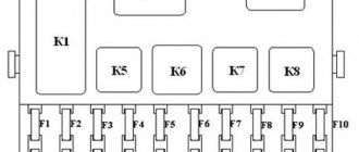
VAZ 2114 fuse mounting block diagram
The fuse box in the VAZ-2114 is located under the hood, to the left in the direction of travel of the car, on the edge under the left wiper you will see a black box. To open it, you need to move two latches on the left. We remove the cover, there are relays and fuses.
There is a marking on the inside of the cover indicating the purpose of the relays and fuses.
Below is the purpose of all relays and fuses in the VAZ-2113 and 2114
| K1 | Electric fan relay |
| K2 | Relay-breaker for direction indicators and hazard warning lights |
| K3 | Wiper relay |
| K4 | Relay for monitoring the health of brake lamps and side lights |
| K5 | Power window relay |
| K6 | Horn relay |
| K7 | Heated rear window relay |
| K8 | High beam relay |
| K9 | low beam headlight relay |
Circuits protected by fuses
| Fuse no. | Protected Circuits |
| F1(20A) | Relay for turning on rear fog lights. Rear fog lamps. Rear fog lamp activation indicator |
| F2(10A) | Turn signal lamps. Relay-breaker for direction indicators and hazard warning lights (in hazard warning mode). Hazard warning lamp |
| F3(10A) | Interior lighting. Individual interior lighting lamp. Ignition switch illumination lamp. Brake light bulbs. Trip computer |
| F4(20A) | Relay for turning on the heated rear window (contacts). Rear window heating element. |
| F5(20A) | Sound signal. Relay for turning on the sound signal (coil). Horn relay (contacts), Relay switching of the electric fan (contacts). Cooling fan motor |
| F6(30A) | Power window switches. Electric windows. Power window relay (contacts) |
| F7(20A) | Heater motor. Washer motor. Rear window washer motor. Rear window wiper motor. Electric windshield wiper relay (winding). Glove compartment lamp |
| F8(7.5A) | Right fog lamp |
| F9(7.5A) | Left fog lamp. Fog light relay (contacts) |
| F10(7.5A) | Turn indicators in turn signal mode and corresponding indicator lamp. Fan motor activation relay (winding). Indicator lamp for fuel reserve, oil pressure, parking brake, brake fluid level. Battery charge indicator lamp. Instrument cluster.Voltmeter. Carburetor electro-pneumatic valve control system. Parking brake warning light relay |
| F11(7.5A) | Side lamps on the starboard side |
| F12(7.5A) | Right headlight (low beam) |
| F13(7.5A) | Left headlight (low beam) |
| F14(7.5A) | Left headlight (high beam). Indicator lamp for turning on the high beam headlights. |
| F15(7.5A) | Right headlight (high beam). |
| F16(15A) | Relay-breaker for direction indicators and hazard warning lights (in direction indicator mode). |
Connection diagram inside the VAZ-2114 and VAZ-2115 fuse box
(the outer number in the designation of the wire tip is the number of the block, and the inner number is the conventional number of the plug)
How to eliminate other causes of turn signal failure
There are several other malfunctions that lead to incorrect operation of turn signals, namely:
- The turn signal does not turn off automatically when you turn the steering wheel - the switch will need to be replaced;
- the turn signal blinks very quickly - most likely one of the lamps has burned out (you will need to check and, if necessary, replace it with a new one), however, the reason may be oxidation of the tracks inside the mounting block or oxidation of the chip in the rear lights;
- The turn signals burn very dimly - you will need to clear the ground on the turn signals and also check the installed lamps to ensure that their power corresponds to the required indicators;
- the appearance of clicking sounds when the turn signal is turned on - the cause may be a defective relay or in the relay contacts (they may oxidize or simply not fit tightly).
As can be seen from the information above, eliminating any of the causes of failure of the turn signal relay on a VAZ 2114 is not difficult. It is important to do this in a timely manner, then any trip will be safe, both for you and for other road users.
Source: remontvazov.com