Device Features
A Hall sensor is necessary to achieve optimal vehicle performance in terms of technical characteristics. The peculiarity is that the corrector achieves a reduction in fuel consumption. This property allows you to save gasoline, which is important for Russian drivers. The second nuance is the possibility of smooth and multi-level ignition control. The driver can independently set the angle he requires for stable and uninterrupted operation of the vehicle.
Full list of benefits of using the octane system:
- ensuring measured operation of the crankshaft to achieve any load indicators;
- stable spark supply;
- eliminating the possibility of burnout of structural parts of the mechanism valves;
- adjusting the performance of vehicle components;
- quick start of the mechanism after a long period of inactivity (no serious warming up is required);
- significant savings in consumables;
- improving the speed characteristics of the vehicle;
- increased dynamic characteristics;
- the ability to make the use of transport, even under unfavorable environmental conditions, economical;
- increase in engine power characteristics.
Octane corrector for electronic ignition systems with a Hall sensor - its circuit looks simple. Connects via wires to structural parts of the car.
How to check VROZ
To check the VROZ, you must first turn off the engine to avoid various critical situations.
Next, the distributor is disassembled:
- You need to remove the distributor cover and the slider itself;
- Next, remove the plastic protection, which is located after the slider;
- Remove the tube through which the vacuum flows.
Then you need to create an artificial vacuum:
- He sucks in air through his mouth;
- At the same time, you need to watch the movement of the diaphragm.
During normal operation of the VROZ, the diaphragm must be retracted into the housing during vacuum, thereby moving the DH plate (Hall sensor). Otherwise, if the diaphragm remains stationary, the VROZ must be replaced.
Here's how the replacement is done:
- The stop washer is dismantled;
- The diaphragm rod is disconnected from the plate;
- The fixing screws of the VROZ housing are unscrewed;
- The regulator is removed from the distributor;
- A new VROZ is installed.
Scope of application
Despite the simplest design of the device, it becomes necessary for a number of domestic and imported cars. The benefits are felt more in one car and less in another, but in any case they will be there.
Electronic equipment is used for domestic vehicles of the brands IZH, VAZ, ZAZ, GAZ and Moskvich. In foreign production it is used in Audi, Opel, Volkswagen and others. To find out exact compatibility, look at the product's service sheet.
Principle of operation
The system is at its simplest. Using a mechanism, the device transmits command signals received from the driver to the structural elements at lightning speed. In this case, the Hall principle responds to determining and switching speeds and switches the located contacts. The octane corrector of the electronic circuit acts as a kind of analog converter. Maybe:
- measure current without destroying the circuit in the event of a short circuit or malfunction;
- increasing the speed of operation of the device mechanisms;
- increasing vehicle engine power.
In addition to it, a number of other devices are installed in modern cars. Together they regulate the functioning of the device and prevent failures and short circuits from affecting the condition of the nodes. These include inductive and optical devices.
It is connected to the distributor block, forming a device similar to a breaker.
Using an octane corrector for the ignition system with a Hall device allows you to make the operation of a domestic or imported vehicle correct and uninterrupted. With the device, the driver will not experience difficulties associated with insufficient power or failure of components. In addition, mechanisms with sensors allow you to save money, which is important in the conditions of Russian realities.
Ignition timing corrector - 2
The economic, power and operational parameters of a car engine largely depend on the correct setting of the ignition timing. The factory setting of the ignition timing is not suitable for all cases, and therefore it has to be adjusted by finding a more accurate value in the zone between the appearance of detonation and a noticeable decrease in engine power.
It is known that if the ignition timing deviates from the optimal angle by 10 degrees, fuel consumption can increase by 10% [1]. It is often necessary to significantly change the initial ignition timing depending on the octane number of gasoline, the composition of the combustible mixture and actual road conditions. The disadvantage of centrifugal and vacuum regulators used on cars is the impossibility of adjusting the ignition timing from the driver’s workplace while driving. The device described below allows such adjustment.
The electronic corrector differs from devices similar in purpose [2, 3, 4] in the simplicity of its circuit and a wide range of remote setting of the initial ignition timing. The corrector works in conjunction with centrifugal and vacuum regulators. It is protected from the influence of bouncing contacts of the breaker and from interference from the vehicle’s on-board network. In addition to correcting the ignition timing, the device allows you to measure the engine crankshaft speed. The described one differs from the digital corrector [5] in that it provides smooth adjustment of the correction angle, contains a smaller number of parts and is somewhat easier to manufacture.
Main technical characteristics: Supply voltage. V 6…17 Current consumption when the engine is not running. And, with closed breaker contacts 0.18 with open breaker contacts 0.04 Frequency of triggering pulses. Hz ... 3.3 ... 200 Installation initial angle of OZ on the distributor, degrees .... '20 Limits of remote correction of the angle of vision. deg…….. 13…17 Delay pulse duration, ms: maximum…. 100 smallest…. 0.1 Duration of the output switching pulse, ms…….. 2.3 Maximum value of the output switching current. A . . . 0.22
Engine operation at the setting angles specified by the corrector is possible if the pulse from the chopper is delayed for a time: T3=(Fr-Fk)/6n=(Fr-Fk)/180*Fn, where Fr, Fk is the initial advance angle ignition, installed by the distributor and corrector, respectively; n — crankshaft rotation speed; Fn=n/30 sparking frequency.
Figure 1 shows, on a logarithmic scale, the dependence of the spark delay time on the crankshaft speed, calculated for various values of the initial ignition timing set by the corrector. This graph is convenient to use when setting up and calibrating the device.
In Fig. Figure 2 shows the characteristics and limits of change in the current value of the ignition timing depending on the engine crankshaft speed. Curve 1 is shown for comparison and illustrates this relationship for a centrifugal regulator with a set initial ignition timing of 20 degrees. Curves 2, 3, 4 are the resulting ones. They were obtained by working together with a centrifugal regulator and an electronic corrector at installation angles of 17, 0 and -13 degrees.
The corrector (Fig. 3) consists of a trigger unit on transistor VT1, two standby multivibrators on transistors VT2, VT3 and VT4, VT5, and an output switch on transistor VT6. The first multivibrator generates a spark delay pulse, and the second controls the transistor switch.
Let us assume that in the initial state the contacts of the breaker are closed, then the transistor VT1 of the starting unit is closed. The forming capacitor C5 in the first multivibrator is charged with current through the emitter junction of transistor VT2, resistors R11, R12 and transistor VT3 (the charging time of capacitor C5 can be adjusted by resistor R12). The forming capacitor C8 of the second multivibrator will also be charged. Since transistors VT4 and VT5 are open, VT6 will also be open and close the “Breaker” terminal of the ignition unit through resistor R23 to the housing.
Design and operation of the vacuum ignition timing regulator
Materials » Automotive electrical equipment » Design and operation of the vacuum ignition timing regulator
Vacuum regulator
(Fig. 3) serves to change the ignition timing depending on the engine load. The vacuum regulator also reduces fuel consumption, especially when the engine operates at low and medium loads. The vacuum regulator operates independently of the centrifugal regulator.
The vacuum regulator is made in the form of a chamber, which is divided into two parts by a diaphragm.
One part is connected by a pipeline to the carburetor mixing chamber, and the other to the environment.
In the part of the chamber that is connected to the carburetor, a special spring is installed, which is adjusted with washers.
The diaphragm is connected by a rod to the movable breaker plate.
Rice. 3. Vacuum regulator device
1 — housing cover; 2 — adjusting gasket; 3 - sealing gasket; 4 — fitting for attaching the tube; 5 - tube; 6 - spring; 7 - diaphragm; 8 — regulator body; 9 — thrust; 10 — thrust axis; 11 — movable breaker plate;
I—position of the vacuum regulator diaphragm:
a - the load on the engine is greater, b - the load is less
When the throttle valve is opened too wide, the vacuum regulator does not work.
As the throttle opening decreases, the vacuum in the mixing chamber increases and the diaphragm bends due to the pressure of the outside air, forcing the draft to move. This rod turns the movable plate of the breaker in the direction opposite to the direction of rotation of the roller, i.e. towards earlier ignition.
To clarify the ignition timing depending on the quality of the fuel used (octane number), an octane corrector located on the distributor body is used (Fig. 4). [5, p. 118]
Rice. 4. Ignition distributor
1 — octane corrector nuts; 2 — screw securing the distributor to the drive housing; 3 - cap oiler; 4 - capacitor; 5 — adjusting eccentric screw; 6 - locking screw.
It consists of two plates: upper and lower. The upper plate is fixed to the distributor body, and the lower plate is attached to the engine block.
The distributor mounted on the engine block can be rotated relative to the shaft using adjusting nuts. The lower plate has divisions, and the end of the upper plate is shaped like an arrow. Each division of the octane corrector scale is equal to 2° of crankshaft rotation.
vacuum ignition rectifier motor
Materials about transport:
Purpose and specialization of the depot The passenger carriage depot is the main production unit of the carriage industry and is intended to carry out scheduled depot repairs of carriages, repair and completion of carriages ...
Lateral controllability of an aircraft The ability of an aircraft to rotate around its longitudinal axis when the ailerons are deflected is called lateral controllability. Rice. 29 Airplane roll when ailerons are deflected The principle of aileron operation ...
Dynamics of the crank mechanism Dynamic calculation of the engine consists of determining the total forces and moments acting on the parts of the crank mechanism. We build a detailed indicator chart based on the calculation results...
How to check the vacuum ignition timing regulator
One of the important parts of the vehicle is the vacuum ignition timing regulator. According to its functions, this element acts as a kind of stabilizer in case of unstable operation of the power unit. The operation of the motor cannot be called stable without the correct functioning of this part. In general, the main task of the vacuum advance regulator is considered to be precisely the regulation of the ignition at the moment of changing the opening angle of the car throttle. That is, it begins to perform its work when the load of the power unit changes. Since at low loads the cylinders are filled less with the working mixture, this means that the pressure at this moment will decrease. At the same time, due to contamination of the mixture with gases, it will increase, and accordingly, the combustion rate will significantly decrease. In this case, a large ignition timing angle is considered a necessary condition. In order to correct the exact ignition timing, a regulator is needed. If the load decreases, the shutter closes at the place where it is connected, which leads to an increase in the diaphragm. The pressure difference acts on the diaphragm, which moves, overcoming the force of the spring, and then, with the help of traction, turns the moving plate towards the rotation of the cam.
Vacuum ignition timing regulator does not work
The vacuum ignition timing regulator is designed to change the ignition timing (ignition timing) depending on the load on the engine (when the throttle valve is opened or closed).
It works due to the vacuum in the intake manifold of the car engine.
Using the example of the vacuum ignition timing regulator of the VAZ 21093 car, we will try to figure out why it happens that it does not work.
Signs that the vacuum regulator is not working
The engine pulls poorly after pressing the gas pedal
Instead of some “pickup” after pressing the gas pedal and increasing engine speed, the driver feels a lack of traction and the engine “goes dull.” This is especially noticeable when driving uphill.
Causes of vacuum regulator malfunction
Loss of tightness
Since the entire operation of the vacuum regulator is based on supplying a vacuum (vacuum) to its body, the slightest violation of the tightness of this system leads to malfunctions.
The “culprits” for the loss of tightness: the tube (jumped off, frayed), the body of the vacuum regulator was leaky.
The diaphragm is “broken”
The main working part of the vacuum regulator is the diaphragm (membrane) in its body. Due to its movement under the influence of vacuum, the distributor support plate moves and the ignition timing increases or decreases. If the diaphragm is damaged, this entire system simply will not work.
Sticking rod and/or support plate
Even a slight wedging of the support plate or rod will lead to the fact that the ignition timing will not change since the vacuum regulator does not have enough power to move it.
Rod of the vacuum ignition timing regulator and the distributor support plate for VAZ 21083, 21093, 21099 cars
Clogged fitting and its channel with the outlet hole in the carburetor
Due to soot deposits emitted into the intake manifold during engine operation, the opening of the vacuum supply channel going into it into the vacuum regulator system becomes clogged over time. In particularly advanced cases, both the channel and the fitting under the tube become clogged. The vacuum from the intake manifold stops flowing into the tube and then into the regulator body, and it stops working.
How to troubleshoot the vacuum ignition timing regulator?
The operation and serviceability of the vacuum regulator can first be checked. To do this, with the engine running, remove the regulator tube from the fitting on the carburetor and create a vacuum in it with your mouth (suck air towards you). The engine speed should immediately increase, since due to the vacuum created, the diaphragm in the housing bends, moves the thrust, and it, in turn, moves the support plate counterclockwise, making the angle earlier. More information about ways to check the serviceability of the vacuum ignition timing regulator on the page: “Checking the vacuum ignition timing regulator.”
If this does not happen, check the condition of the tube and the tightness of its fit on the fittings. We remove the distributor cover and check the condition and ease of movement of the rod and support plate. The regulator body and diaphragm can only be checked by replacing it with a new one or a known good one.
We replace damaged parts and check again.
Notes and additions
If, after eliminating the malfunction of the vacuum ignition timing regulator, the engine continues to be “stupid,” we check the centrifugal ignition timing regulator, the power mode economizer, the gas pump, and the carburetor accelerator pump, since they are also responsible for increasing the power and throttle response of the engine.
More articles on the ignition system of the carburetor engine of the VAZ 21093 car
Design and principle of operation
The main task of the vacuum advance regulator is to regulate the ignition during a change in the throttle opening angle, that is, during a change in the load on the engine. During light loads, the filling of the cylinders with the working mixture decreases, and hence the pressure at the moment of direct ignition.
At the same time, contamination of the entire mixture with gases from the residue increases, and this reduces the combustion rate. This, in turn, requires a larger ignition advance angle. That is, the sparking process must occur earlier. An increase in load brings a decrease in residual gases. The air loss coefficient is placed in the range of 0.8–0.9.
In order to correct the exact ignition timing, a regulator is needed. If the load decreases, the shutter closes at the place where it is connected, which leads to an increase in the diaphragm. The pressure difference acts on the diaphragm, which moves, overcoming the force of the spring, and then, with the help of traction, turns the moving plate towards the rotation of the cam. That is, the sensor rotor. In the process, the ignition angle increases.
If the load increases, the throttle valve itself opens, and the vacuum in the regulator drops. In this case, the spring shifts the diaphragm to the left, and does the same with the thrust. The latter rotates the plate, as well as the breaker, in the direction in which the cam rotates. This reduces the ignition angle.
As for the device, the vacuum ignition timing regulator is usually installed on the distributor. It also consists of a static body with a cover that is made of fabric. These two elements are separated by a special diaphragm. Also, the vacuum ignition timing regulator includes a spring of the same diaphragm and a thrust spring. It is clear that it is he who is responsible for vacuum ignition timing.
Where is the VROZ located and what is the danger of its failure?
VROZ is installed on the distributor. The latter consists of a body with a lid made of fabric. The two elements are separated by a special diaphragm. VROZ includes springs and other components.
How to check ignition timing
A malfunctioning regulator can easily result from problematic engine operation. There will be no ignition adjustment.
It is enough to look at how the crank shaft rotates after insulating the hose with VROZ to understand the importance of the operation of the regulator.
The cause of VROZ failure may be jamming of bearings or loosening of fasteners. The tightness of the VROZ is a very important thing, and it can easily be damaged if the tube leaks air somewhere. Also, the loss of tightness will be affected by low tightness of the fitting, critical damage to the diaphragm and much more.
You can clearly see what happens to the engine when the VROZ is damaged or loses its tightness in the table below.
Article on the topic: Differences between a diesel engine and a gasoline engine - which is better to choose?
| Causes of malfunction | Remedies |
| Insufficient gap between breaker contacts | It will be enough to adjust the gap |
| Contamination of the distributor slider and cover, the appearance of cracks in them, leading to greater leakage of high voltage current, burning of the sockets in the cover | Wipe the slider and lid. If there are cracks or burnt sockets, the faulty slider or cover must be replaced |
| Burning breaker contacts | Clear contacts |
| Excessive wear of the roller bushings, uneven wear of the distributor cam, severe wear of the moving contact axis | Disassemble the distributor, replace worn parts, assemble and adjust the distributor |
| The engine does not develop full power | |
| Breaker lever spring weakening | Check the pressing force of the breaker contacts and, if it is lower than required, replace the spring |
| Ignition installed incorrectly | Check that the ignition is installed correctly |
| The centrifugal ignition timing regulator is faulty | Disassemble the distributor and fix the problem |
| The vacuum ignition timing regulator is faulty | Check the condition of the vacuum regulator tube and, if damaged, replace the tube. If there is no damage, check the vacuum regulator on the stand and replace if necessary. |
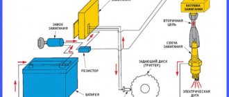
Contactless ignition system
The ignition system (IS) serves to create a pulse voltage and timely ignite the combustible mixture in the combustion chambers of the power unit. It is the main part of the vehicle's energy supply system.
The evolution of the “seven” ignition began with a contact-type mechanism. Its feature was the process of generating an electrical impulse using a group of contacts located in the distributor. The constant mechanical and electrical loads to which the contacts in such a system were subjected led to the fact that car owners very often had to clean them, change them and adjust the gap between them.
In the early 90s of the last century, the “seven” received contactless ignition. It made the life of the owners of these cars much easier, because in its design there were no longer any burning contacts that required constant adjustment. They were replaced by an electronic switch that does not require any maintenance.
The design of the contactless ignition system and the principle of its operation
The contactless ignition system (BSI) of the VAZ 2107 includes:
- electronic (transistor) switch;
- transformer coil (two-winding);
- distributor (distributor) with Hall sensor, contact cover and slider;
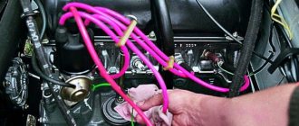
- set of high-voltage wires;
- candles.
Each of these elements is a separate part and performs its functions independently of other components. Sparking in a VAZ 2107 engine with a non-contact ignition system occurs according to the following algorithm:
- When voltage is applied to the starter, its rotor begins to rotate the crankshaft, which, in turn, rotates the distributor shaft with the slider.
- The Hall sensor reacts to this rotation, registers the rotation of the distributor shaft and transmits a signal to the switch. The latter, having received a signal from the sensor, turns off the current supplied to the primary (low-voltage) winding of the coil.
- At the moment the current is turned off, a powerful voltage pulse occurs in the secondary winding of the transformer, which is transmitted through the central wire to the slider (moving contact) located at the end of the distributor shaft.
- The slider, moving in a circle, alternately comes into contact with four fixed contacts located in the distributor cover. At certain moments, it transfers tension to each of them.
- From the stationary contact, current flows through a high-voltage wire to the spark plug, causing sparking at its electrodes.
In a contactless ignition system, the role of a breaker is performed by a Hall sensor and a switch
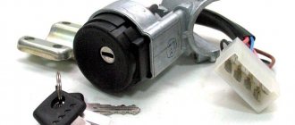
Installation Tools
For all work carried out we will need:
- key to 38;
- open-end or socket wrench 13;
- a 12 V control light with two wires attached to it (each wire is approximately 20 cm long).
DETAILS: Photo report on replacing the cabin filter in Opel Corsa C. Instructions on how to change the cabin filter in Corsa
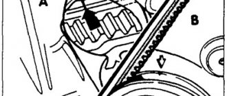
How to work with tags correctly
There are three marks on the engine block next to the crankshaft pulley, each with its own length. You can feel these marks from the driver's side, but only strictly with the engine not running, since the pulley rotates at high speed when the engine is running! The shortest of them will mean that the ignition is advanced by 10 degrees or 10 degrees to the top dead center of the piston in the cylinder, the middle mark by 5 degrees and short - 0 degrees.
Step-by-step description with photos and diagrams
- If during the work you accidentally messed up the ignition setting, then do not rush to remove the valve covers to understand when the compression stroke begins. Do the following: remove the spark plug in the first cylinder and plug the hole with a small, tight plug made from a rag soaked in water. Having made sure that no one is standing nearby and will not be harmed by the impromptu plug flying out, in short series we turn the crankshaft with the starter for literally a split second, turning the starter on and off, and at the moment when the plug flies out with a characteristic sound from the spark plug hole, we stop turning the starter.
- Now, turning the crankshaft a little at a time by the pulley nut with a 38 wrench, we ensure that the marks on the pulley and the cylinder block coincide with the middle mark, which means 5 degrees.
- We unhook the latches from the distributor cover and look at the direction of the slider: when it is positioned as in the photo, then half the job is already done. If not, then use an open-end wrench or a 13-socket wrench to unscrew the nut, remove the distributor and put everything back in the required position.
Required position of the distributor and slider relative to the cylinder block
We make a mark with a marker on the cylinder block to further optimize the ignition settings.
For ease of ignition settings
- Now we connect our light bulb with one wire to the positive terminal of the ignition coil, and the second wire to ground. We remove the central wire of the coil from the distributor cover and fix it at a distance of approximately 1-5 mm from ground. This is done in order to prevent breakdown of the ignition coil to ground.
- Having turned on the ignition, slowly turn the ignition distributor housing (distributor) in the direction of movement clockwise and watch when the light goes out. If it didn’t burn, then we leave everything as is.
- Slowly rotate the distributor housing in the opposite direction, until the light comes on and use a 13 key to secure the housing.
- Turn off the ignition, return the distributor cap and the central wire to their place. Unhook the wires of the control lamp.
What is the danger of failure?
Any malfunction of the regulator can easily result in vacuum ignition timing becoming impossible. You can also judge the performance of this part by observing the change in the crankshaft speed when insulating a vacuum-type hose.
This can also be judged by the movement of the rod of this part with varying crankshaft speed.
The cause may also be jamming of the same bearings or loosening of the fastening screws. As a rule, the tightness disappears after damage occurs to the tube that approaches the regulator from the suction-type manifold. This may be accompanied by low fitting tightness, as well as critical damage to the diaphragm. Because of this, air gets inside the mechanism, which leads to a decrease in vacuum in the cavity of the vacuum chamber itself. As a result, this part is simply deprived of the ability to change the ignition timing within the required limits during differences in engine loads.
If the regulator stops functioning, this means that there is no vacuum ignition timing due to the loss of tightness of its chamber or due to weakened springs of the diaphragm itself.
Regulator malfunction: what is the risk?
The occurrence of malfunctions with the vacuum regulator can result in vacuum ignition timing becoming impossible. In practice, you can understand how exactly a given part works through observations. It is important to pay attention to the change in crankshaft speed when insulating the vacuum hose. The cause may be jamming of the bearings or loosening of the fastening screws. The tightness disappears after damage occurs to the tube that approaches the regulator from the suction-type manifold. This may be accompanied by low fitting tightness, as well as critical damage to the diaphragm. In this case, air enters the mechanism and a vacuum chamber occurs. Because of this, the part cannot subsequently change the ignition timing.
What is VROZ and how does it work?
VROZ is a device that resembles a stabilizer in its operation, the task of which is to control the operation of the motor. Without VROZ, the engine will definitely not function stably.
If you delve into the functional tasks of the device in more detail, it becomes clear that the VROZ not only controls the operation of the engine, but regulates the ignition system during load on the power plant.
Note. As is known, during a heavy load on an internal combustion engine, its cylinders begin to actively fill with fuel assemblies (fuel mixture), thereby increasing the pressure at the moment of ignition. Conversely, if the load is light, the pressure decreases, which also reduces the combustion rate.
VROZ is able to regulate the points described above. When required, the advance angle or SOP is automatically reduced or increased.
VAZ 2109: do-it-yourself distributor repair
Repair of ignition distributor VAZ
Correct operation of the distributor (also known as the ignition distributor) affects the stable operation of the engine, since the ignition distributor controls the supply of spark to the spark plugs, both while driving and at idle. This is especially important for dynamics when the engine picks up speed. The main functions of the distributor are setting (adjusting) the moment of spark formation, in accordance with certain factors (changes in speed, engine load, etc.), as well as correct distribution of the spark among the cylinders. If the engine of a VAZ 2109 car jerks, the car starts poorly or does not start at all, the VAZ 2109 distributor may need to be repaired. The repair process is not difficult, you do not need the knowledge of an auto electrician, our instructions will help you identify and fix the problem.
Diagnostics
To check this mechanism, I advise you to first turn off the engine to avoid critical situations. After this, remove the distributor cover, and then the slider itself. Behind the slider itself there will be a protective plastic screen, which should also be removed. After removing the screen, we proceed to removing the tube responsible for supplying vacuum to our regulator. Its connection is located on the carburetor fitting. Now, with our own efforts, that is, with our mouth, we create a vacuum in the tube, drawing air into ourselves. During this, you need to monitor the movement of the thrust of the diaphragm of the mechanism itself. If everything is normal, then it should be retracted into the body of this part and, thus, move the Hall sensor plate. If this does not happen, then the regulator must be immediately replaced with the same one, only in good working order. To do this, you need to remove the lock washer and disconnect the diaphragm rod from the corresponding lock-type plate. After this, unscrew a couple of screws securing the timing mechanism housing to the distributor. Now the regulator can be safely removed and replaced with a new one, installing it in the reverse order.
As for checking the tightness, it can only be done after removing this part. Such testing work is carried out using a pump. The idea is to lower the part into a container of water and start pumping air directly into its vacuum chamber. If you see air bubbles coming out, then the place where they came out is the damaged area due to which the regulator was not sealed.
If during such a procedure air comes out directly at the fitting, everything can be solved by tightening it. If air escapes at the place of rolling itself, then I strongly recommend sealing the joint as best as possible with a hammer. This can also be done by coating the damaged areas with special epoxy glue, but only after the regulator has been completely dried and cleaned.
If the diaphragm is damaged, then it is impossible to do without completely replacing the mechanism. As a rule, its operation is disrupted due to wear of its parts, corrosion of the bearing races that belong to the contact plate, or due to corrosion of the balls themselves.
Symptoms of a problem
The main signs indicating a malfunction of the ignition distributor:
The most common faults:
It is necessary to replace faulty parts in all of the above cases, except the very last one.
Oil entering the distributor
Let's consider a malfunction such as oil getting into the distributor using the example of a real case:
Removal and installation
In order to easily repair the distributor, you must be able to remove it, and then (after repair) install it in place:
We disassemble the distributor
Before you start disassembling the distributor, you need to remember that each wire on its cover is installed in the sequence of operation of the cylinders (of which only the first is indicated, you need to install the others counterclockwise, while looking from the side of the plastic tank with antifreeze). If necessary, replace the cover or slider - dismantling the ignition distributor is not required. We repair the VAZ 2109 distributor with our own hands in the following sequence:
Slider top and bottom view (1-external contact, 2-leaf spring, 2-1 kOhm resistor)
Unscrew the two screws and remove the Hall sensor support plate
Unscrew and remove the vacuum corrector
Using a screwdriver, pull out the support plate and check the condition of its bushing
Remove the locking ring
We knock out the pin from the coupling
We take out the roller assembly with the centrifugal regulator
We pull off the driven plate from the centrifugal regulator
At this point, the repair of the distributor is completed, install it in place, as already described above , if something is not clear, type in the search: VAZ 2109 distributor repair video. It is also worth recalling that for the VAZ 21093, repair of the distributor is carried out in the same way, because the VAZ 2108-21099 models have such a distributor device.
Ignition adjustment
If, when removing the distributor, you did not leave marks, forgot how it was originally located, turned the shaft, and the piston left the top dead center position, then the cost for you is the time spent on adjusting the ignition. Before proceeding with the adjustment, the following conditions must be met:
Scale on the clutch housing and mark on the flywheel
Let's move on to the adjustment process:
The ignition adjustment for VAZ 2108-21099 is now complete.
How to check VROZ
To check the VROZ, you must first turn off the engine to avoid various critical situations.
Next, the distributor is disassembled:
Then you need to create an artificial vacuum:
- He sucks in air through his mouth;
- At the same time, you need to watch the movement of the diaphragm.
During normal operation of the VROZ, the diaphragm must be retracted into the housing during vacuum, thereby moving the DH plate (Hall sensor). Otherwise, if the diaphragm remains stationary, the VROZ must be replaced.
Here's how the replacement is done:
- The stop washer is dismantled;
- The diaphragm rod is disconnected from the plate;
- The fixing screws of the VROZ housing are unscrewed;
- The regulator is removed from the distributor;
- A new VROZ is installed.