Engine LADA 21099 (VAZ 21099)
- 1. Crankshaft;
- 2. First main bearing cover;
- 3. Camshaft drive pulley;
- 4. Generator drive pulley;
- 5. Front crankshaft oil seal;
- 6. Oil pump;
- 7. Connecting rod;
- 8. Front toothed belt protective cover;
- 9. Piston;
- 10. Inlet valve;
- 11. Exhaust valve;
- 12. Camshaft drive belt;
- 13. Camshaft pulley;
- 14. Rear toothed belt protective cover;
- 15. Camshaft oil seal;
- 16. Front camshaft bearing housing:
- 17. Camshaft;
- 18. Oil separator mesh for crankcase ventilation system;
- 19. Cylinder head cover;
- 20. Oil separator cover;
- 21. Rear camshaft bearing housing;
- 22. Fuel pump drive eccentric;
- 23. Ignition distributor sensor;
- 24. Housing of auxiliary units;
- 25. Cooling jacket outlet pipe;
- 26. Spark plug;
- 27. Cylinder head;
- 28. Cylinder block;
- 29. Retainer with rear crankshaft oil seal:
- 30. Flywheel:
- 31. Bracket with front engine mount support;
- 32. Power unit (engine with gearbox and clutch);
- 33. Bracket with support for left engine mount;
- 34. Bracket with rear engine mount support;
- 35. Front engine mount support;
- 36. Front engine mount bracket;
- 37. Oil sump;
- 38. Oil level indicator;
- 39. Plug for draining oil from the crankcase;
- 40. Left engine mount bracket;
- 41. Left engine mount support;
- 42. Rear engine mount bracket;
- 43. Rear engine mount support.
- 1. Oil pump receiver;
- 2. Oil sump;
- 3. Oil filter:
- 4. Cylinder block:
- 5. An exhaust manifold;
- 6. Inlet pipe;
- 7. Coolant pump inlet pipe;
- 8. Carburetor heat shield;
- 9. Thermostat;
- 10. Fuel pump;
- 11. Oil filler cap;
- 12. Cylinder head cover;
- 13. Front camshaft bearing housing;
- 14. Camshaft;
- 15. Cylinder head;
- 16. Spark plug;
- 17. Cylinder head gasket;
- 18. Piston;
- 19. Piston pin;
- 20. Connecting rod;
- 21. Crankshaft connecting rod bearing shell;
- 22. Connecting rod cover;
- 23. Crankshaft;
- 24. Oil cap;
- 25. Pusher;
- 26. Valve holder;
- 27. Spring plate;
- 28. Adjusting washer;
- 29. Inner valve spring;
- 30. Outer valve spring;
- 31. Spring support washer;
- 32. Retaining ring;
- 33. Valve guide;
- 34. Valve seat;
- 35. Inlet valve;
- 36. A. The clearance in the valve drive mechanism on a cold engine: 0.2 mm for intake valves and 0.35 mm for exhaust valves;
- 37. B.Valve timing diagram;
- 38. I. Inlet of the combustible mixture;
- 39. II.Compression;
- 40. III.Working stroke;
- 41. IV.Issue.
Source
VAZ-2109 diagram
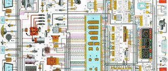
The VAZ-2109 car was produced at AvtoVAZ from 1987 to 1997. Years of production 21099: 1990-2004 - in Russia, 2004-2011 - in Ukraine. Here are colored wiring diagrams (for the injector and carburetor) with a description of all the elements for various modifications. The information is intended for self-repair of cars. Electrical circuits are divided into several blocks for ease of viewing via a computer or smartphone; there are also circuits in the form of a single picture with a description of the elements - for printing on a printer.
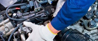
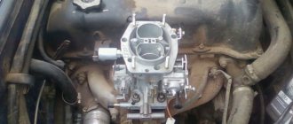
Engine Features
VAZ 21083 (carburetor) has several characteristic features that are important for the owner of a V8 to know. Description of some engine features:
- It is worth refusing to use low-octane fuel for this model. This negatively affects the operation of the carburetor. Initially, the engine was created for 93 gasoline.
- The wad is located on top, which allows you to get rid of inertial moments.
- The engine has a belt drive - the car owner should change the guide rollers and the belt itself every 50 thousand km.
- In this series of units, the piston diameter was increased to 82 mm.
- The reliability of the motor is explained by its design. If the drive belt breaks, the moving pistons do not collide with the valves. This also makes it easier to overhaul the engine.
In addition, the unit is lightweight and economical. Such features appealed to many domestic car enthusiasts. The injector provides more economical fuel consumption, as well as ease of starting the engine in any weather conditions.
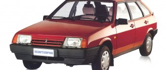
Modifications of VAZ-2109
VAZ-2109 . The basic model, which was produced from 1987 to 1997, was equipped with a 1.3-liter VAZ-2108 carburetor engine with a capacity of 64 horsepower.
VAZ-21091 . Modification of a car with a derated VAZ-21081 engine, 1.1 liter and 54 horsepower. It was mass-produced from 1987 to 1997.
VAZ-21093 . Modification of a car with a VAZ-21083 carburetor engine, 1.5 liters and 73.4 horsepower. Serially produced from 1988 to 2006.
VAZ-21093i . Modification with a VAZ-2111-80 injection engine, 1.5 liters. the first prototype appeared in 1994, mass production began in November 1998.
VAZ 21093-22 . Model made specifically for the Finnish market. It features improved interior trim, pre-installed alloy wheels and a new dashboard. The car was equipped with a 1.5 liter injection engine. Produced from 1995 to 1998.
VAZ-210934 . An all-wheel drive SUV with a VAZ-21093 body mounted on a Niva frame, on which the suspension, steering, engine, gearbox and transfer case from the same VAZ-2121 Niva model were already installed.
VAZ 2109-90 . A variant of the car, which was equipped with a compact two-section Wankel rotary piston engine with a volume of 654 cm3.
VAZ-21096 . Export modification of the VAZ-2109 for countries with left-hand traffic, the steering column was located on the right.
VAZ 21097 . Export modification of VAZ 21091 with right-hand drive.
VAZ 21098 . Another export modification, but this time the VAZ 21093 model with a right-hand steering column.
VAZ-2109 Carlota . A car produced from 1991 to 1996 in Belgium by Scaldia-Volga.
VAZ-21099 . The next independent car model, which is a modification of the “nine”. This car had a 4-door, 5-seater sedan body and a rear overhang extended by 200 mm.
Specifications
VAZ-2108
The VAZ 21099 engine has the following technical characteristics:
| OPTIONS | VALUES |
| Years of manufacture | 1990 - 2011 |
| Weight | N. d |
| Cylinder block material | cast iron |
| Motor power system | carburetor |
| Type of cylinder arrangement | In a row |
| Engine displacement | 1.5 liters |
| Engine power | 73 l. With. |
| Number of cylinders | Four |
| Number of valves | Two |
| Piston stroke | 71 millimeters |
| Cylinder diameter | 82 millimeters |
| Compression ratio | 9.8 |
| Torque Nm/rpm | 106 /360 |
| Environmental standards | EURO 2 |
| Fuel | petrol |
| Fuel consumption | 7.8/100 km |
| Oil | 5W-30 |
| Oil volume in crankcase | 3.5 liters |
| When replacing, pour | 3.2 liters |
| Oil change is carried out | every 15 thousand km |
| Motor life | |
| - according to the plant | 125 |
| - on practice | 250 |
The following models are equipped with this motor: 21093, 21099, 21111,.
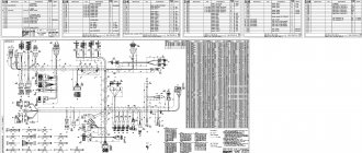
Wiring diagram for VAZ-2109 carburetor
- Headlight.
- Electric motor for headlight glass cleaning system. An optional part, used mainly on export vehicles.
- Limit switch for powering the engine compartment lamp.
- Klaxon.
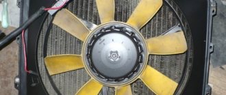
- An electric motor drives a fan installed on the radiator of the cooling system.
- Temperature indicator that provides a control signal for the electric drive of the fan impeller.
- Alternator.
- Fluid supply valve for headlight glasses. Used in conjunction with paragraph 2.
- Fluid supply valve for the glass of the fifth door.
- Fluid supply valve to the front glass.
- Spark plugs.
- Hall sensor used to distribute ignition pulses.
- Coil.
- Limit switch for reverse gear lights.
- Fluid temperature meter in the cooling system.
- Starter.
- Accumulator battery.
- A sensor that measures the fluid level in the brake booster.
- Switch that controls the ignition system.
- Sensor for determining the position of the top dead center of the piston of the first cylinder. Installed on some export VAZ 2109 with a diagnostic system. Found only on cars before 1995.
- Diagnostic block. Optional element, installed together with item 20.
- Controller for controlling the solenoid valve installed in the carburetor.
- Starter switch contact block.
- Limit switch on the carburetor.
- Economizer valve.
- Sensor signaling an emergency decrease in oil pressure.
- Washer pump drive.
- Fan impeller motor for ventilation and heating systems.
- Resistance providing additional fan speeds.
- Speed shifter.
- Windshield wiper drive.
- Cigarette lighter.
- Illumination system for levers for adjusting heater operating parameters.
- Socket for additional equipment.
- Lamp for auxiliary lighting of the engine compartment.
- Illumination system for the glove box on the instrument panel.
- Relay and fuse link mounting block.
- Instrument panel light switch.
- Parking brake lamp limit switch.
- Brake lamp limit switch.
- Steering column switch lever block.
- Exterior lamp switch.
- Hazard switch.
- Turn on the rear fog lamp.
- Bimetallic fog lamp fuse.
- Heated glass switch on the fifth door.
- Turn signal repeaters on the front fenders.
- Central interior lighting.
- Individual lampshade.
- Switches for backlight operation on the middle pillars.
- Ignition switching unit.
- Egnition lock.
- “Low” type instrument cluster.
- Choke limit switch on the carburetor.
- Rear lights.
- Fuel level meter in the tank.
- Heated glass.
- Rear wiper drive.
- Two lamps for room illumination.
Malfunctions
| Causes | How to fix the problem |
| Foreign objects and debris got into the fuel line, which led to severe blockage. The fuel pump, carburetor filter, fuel line may be clogged. | Carry out a complete cleaning of the fuel supply systems to the engine. This can be done either with water pressure or with compressed air. |
| Failure of the pump supplying fuel to the engine. | Conduct a full diagnostics of the pump, identify the breakdown, and replace the faulty part with a working one. |
| Foreign objects or debris have entered the fuel filter. | Cleaning the filter yourself is quite difficult and time-consuming. It is much cheaper and faster to replace it with a new one. |
| Ignition problems. The engine starts poorly or does not start at all. | Conduct diagnostics of the ignition system, seek help from specialists. Partial or complete disassembly of the VAZ 2109 engine may help find the fault. |
Problems and malfunctions during operation of the solenoid valve. This part is part of the carburetor and affects the ignition process, which is why its breakdown leads to the following troubles
| Causes | How to fix the problem |
| Broken or damaged wiring. This problem affects the operation of the valve control unit, which leads to faulty fuel supply and reduces the power of the VAZ 2109 engine. | Carry out a full check of each circuit, find the damaged wire, replace it with a intact one, and check the operation of the system. |
| The solenoid valve control unit does not work. | In this case, replacing or repairing it yourself is risky due to the complex structure of the device. It is advisable to entrust repairs to specialists. |
| During the initial operating cycle of the engine, the carburetor air damper does not operate, which should open at the first flashes in the engine cylinders. | The cause of this breakdown may be depressurization of the starting device in the carburetor. |
Engine problems
| Causes | How to fix the problem |
| The idle speed of the engine is difficult to adjust and does not work properly. The engine is breathing. | In this case, you will need to carry out a complete setup and adjustment of the idle speed. Disassembling the VAZ 2109 engine also helps to identify the fault. |
| The system responsible for controlling the carburetor solenoid valve is faulty or partially broken. | Carry out a full check of each circuit, find the damaged wire, replace it with a intact one, and check the operation of the system. |
Problems in the operation of the VAZ 2109 carburetor engine
Causes How to fix the problem The carburetor does not work due to severe contamination of the channels or jet. The mentioned parts of the carburetor are cleaned using compressed air. It is important to control the air supply to prevent damage. Liquid has entered the carburetor or jet. Also, use compressed air to clean carburetor systems from residual liquid. Check the fuel tank for sediment and drain if necessary. The starting device does not work due to depressurization of the system. The trigger diaphragm is broken. This may reduce the productivity of the VAZ 2109 engine. Check for damage to the diaphragm, replace it if a malfunction is detected. Problems with the ignition system. Complete or partial inoperability. Carrying out diagnostics of the ignition system, replacing faulty parts with new ones. Air entering the brake booster compartment. This usually happens due to a torn vacuum hose. Such a breakdown affects the performance of the econometer, ignition distributor and vacuum regulator-sensor. Check the hose, find damage and repair it. You can also completely replace the hose
It is necessary to pay attention to the mounting clamps; if necessary, they should be tightened. Damage to the gasket in the intake manifold connections. Such a breakdown leads to air leaks into the intake manifold.
Affects the performance of the carburetor and engine of the VAZ 2109. Check for damage to the intake pipe. Tighten all nuts. If this does not help, then most likely you will need to replace the gaskets with new ones.
Equipment diagram for VAZ-2109 injector
The VAZ 2109 wiring for the injector has many connectors for connecting sensors to the computer.
- TPS (throttle position sensor);
- DPKV (crankshaft position sensor);
- DT (temperature sensor);
- DSA (vehicle speed sensor);
- Canister purge valve;
- MAF (mass air flow sensor);
- DD (knock sensor) and others.
The weak point of the harnesses is the power wiring on the bottom shelf of the radiator, which is constantly exposed to high temperatures and in this place it is in no way protected from water and dirt. Another problem is a harness under the carpet next to the driver's seat. Moisture constantly accumulates there, and in order to remove it, you need to dry the floor, inevitably tugging on the rope.
Since the mid-90s, VAZ 2109 began to use engines with an injection system, which greatly changed the electrical layout of the engine compartment and instrument panel. Below is an electrical diagram of a 1999 car with an ECM type GM ISFI-2S and January 4/4.1.
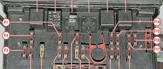
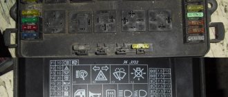
Relay and fuse box diagram 2109
The fuse blocks do not depend on the fuel injection system used - carburetor or injector. BP will differ only by year of manufacture of the car. That is, the mounting blocks for the carburetor and injector are the same. The VAZ 2109-099 fuse box (carburetor, injector) is located under the hood, in the compartment in front of the windshield on the left side.
Fuse block 2114-3722010-18
K1-relay for turning on headlight cleaners; K2-relay-breaker for direction indicators and hazard warning lights; K3 - windshield wiper relay; K4-relay for monitoring the health of lamps; K5-power window relay; K6 - relay for turning on sound signals; K7-relay for turning on the electric heating of the rear window; K8-relay for high beam headlights; K9-relay for low beam headlights; F1-F16 - fuses.
Fuse block 2114-3722010-60
K1 - Headlight wiper relay, K2 - Turn signal and hazard warning relay, K3 - Windshield wiper relay, K4 - Brake light and parking light relay, K5 - Power window relay, K6 - Horn relay , K7 - Rear window heating relay, K8 - Headlight high beam relay, K9 - Headlight low beam relay, F1 - F16 - Fuses, F1 - F20 - Spare fuses.
Attention! The power terminals on the generator often become loose, heat up, spark and melt the wiring. Pay attention to this point when searching for possible faults yourself.
Source
Engine tuning
- direct-flow exhaust system - spider circuit 4/2/1 and resonator with banks;
- sports camshaft – gas distribution modes change.
Tuning 2108
Tuning is usually used to add about 10 horsepower. With. by replacing the carburetor with an injector or a direct-flow muffler. There is a time-consuming option to replace the crankshaft with the following crank diameter. The piston stroke increases by 2 mm, but a KShG kit, precise calculation and adjustment of the mechanism are required.
Thus, the 2108 engine uses advanced technologies from the German automobile industry. The weight and dimensions of the engine have been reduced for transverse placement under the hood of a front-wheel drive car. In two versions, 1.1 l and 1.5 l, the modernization was carried out by employees of the manufacturer's plant.