07/18/2021 14,953 VAZ 2107
Author: Ivan Baranov
As with any car, the generator on the VAZ 2107 injector works in parallel with the battery - these are two power sources for the car, which are used in different modes. The article discusses the generator 37.3701, the principle of operation of the generator with different characteristics, including a maximum current of 80 Amperes, and provides instructions for connecting the unit. The G222 generator set is similar, you just need to pay attention to some differences.
[Hide]
Generator VAZ 2107: purpose and main functions
As with any other car, the generator on the “seven” works in tandem with a battery. That is, these are two power sources in the car, each of which is used in its own modes. And if the main task of the battery is to maintain the functionality of electronic devices during the period when the engine is turned off, then the generator, on the contrary, produces current only when the engine is running.
The main task of the generator set is to generate electrical energy by charging the battery. That is, in many ways (if not all) the performance of the machine depends on how well the generator and battery work.
Generator sets for the VAZ 2107 have been produced since 1982. Their factory marking is G-221A.
Technical characteristics of the generator G-221A
The VAZ 2107 was equipped with two types of generators (carburetor and injection), each of which had its own factory marking: 372.3701 or 9412.3701. Therefore, the operating characteristics of the devices may differ, since injection models consume more electricity, and accordingly, the generator power must be higher.
All VAZ 2107 generators have the same rated voltage - 14 V.
Table: comparison of characteristics of different modifications of generators for VAZ 2107
| Generator name | Maximum output current, A | Power, W | Weight, kg |
| VAZ 2107 carburetor | 55 | 770 | 4,4 |
| VAZ 2107 injector | 80 | 1120 | 4,9 |
Shendys › Blog › VAZ classic generators
What are they, how do they differ in connection?
First, briefly about the operation of the generator. Who knows - scroll down to two lines. If you wrap a wire around something metal and apply electricity to it, you get an electromagnet. This should have been taught in physics classes at school. If you move a magnet or electromagnet next to a winding (made of wound wire), then electricity will appear in the coil, electrons will run in one direction along the wire, then in the other. If you connect a light bulb, for example, it will glow. A car generator works the same way.
The generator pulley rotates through the belt, which turns the rotor (moving part), power is supplied to it through the brushes, and an electromagnetic field appears in the winding.
The stator (the stationary part with three windings) surrounds the rotor, and when the rotor with an electromagnetic field rotates, electricity is generated in the stator windings. The current there is variable (it goes one way and then the other), and that’s why there are diodes. They pass current only in one direction and the result is a constant current.
The generation of generator voltage is made with a reserve so that there is no shortage at low speeds and if there are many consumers of electricity. And the generator can produce, for example, 15 Volts, this is a lot, since at 14.5 V the electrolyte in the battery begins to boil away, and the life of the light bulbs will decrease. When the voltage is high, you can notice it by flickering headlights, for example. In order for the generator to produce 13-14.3 V (it’s different for everyone), variable power is supplied to the rotor from the voltage regulator; if 12V goes to the regulator, then it does not reduce the voltage to the rotor, the magnetic field is large and the voltage generated by the generator increases. If it is higher than the desired value, the regulator reduces the voltage to the rotor and the voltage produced by the generator decreases. We look at the diagram of classic VAZ cars with “round headlights” (VAZ-2101, 2102, 2103 and 2106)
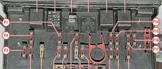
The classics come with three types of generators for connecting G221 - used on VAZ-2101, VAZ-2102, VAZ-2103 and VAZ-2106 The relay regulator is located next to the expansion tank. It is protected through fuse 10 (the latest one) at 8 Amperes.
G-222 was used on old VAZ-2104, VAZ-2105 and VAZ-2107; its voltage regulator is installed directly on the generator itself. Powered by fuse 9 (8 Amp). You can put a mounting block where this fuse will be on the rear fog lights, and then the generator will not work. Then you can connect the orange wires of plug 11 together. The charge light was not connected on all machines, since there was a voltmeter.
And with the advent of the VAZ-2108, instead of the G-222, they began to install the 2108 generator (catalog number 2108-3701010). There is no difference in mounting. But it connects a little differently. Ignition occurs through a light bulb in devices with 61 voltage regulators. When the generator produces current, a plus appears on pin 61 and the lamp goes out. Addition from Dragon2140
:
On the 2108 and subsequent modifications of the generator, the excitation goes through the light bulb - if it burns out, then after stopping the engine the generator will not charge at all and accelerate even to the cutoff. If it self-energizes and charges without a light bulb, it means there are broken diodes in the bridge.
What generators can be installed on the “seven”
The design of the VAZ 2107 allows the installation of not only the G-221A generator. Therefore, if necessary, the driver can install a more powerful device, however, this will require making some changes to the electrical circuit of the car. The question arises: what is the reason for the desire of a car enthusiast to change his “native” generator?
The G-221A was the optimal device for equipping cars at the beginning of their mass production. However, a lot of time has passed since the 1980s and today almost every driver uses modern electronic devices:
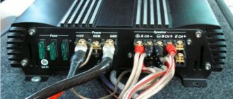
- acoustic system;
- navigators;
- additional lighting devices (tuning), etc.
Accordingly, the G-221A generator cannot cope with high loads, which is why drivers begin to look for more powerful units.
The device of the VAZ 2107 generator
Structurally, the generator on the “seven” has the shape of a cylinder. The cast body contains many small parts, each of which performs its own functions. The main elements of the G-221A are the rotor, stator and covers, which are cast only from a special aluminum alloy.
Rotor
The G-221A rotor consists of a shaft with a corrugated surface, onto which a steel sleeve and poles are pressed. The bushing and beak-shaped poles together form the so-called core of the electromagnet. The core produces an electromagnetic field during the rotation of the rotor shaft.
The excitation winding is also located inside the rotor. It is placed between the poles.
The moving element of the rotor - the grooved shaft - rotates thanks to two ball bearings . The rear bearing is mounted directly on the shaft, and the front bearing is fixed on the generator cover.
Stator
The stator is assembled from special plates 1 mm thick. The plates are made of electrical steel. It is in the stator slots that the three-phase winding is located. The winding coils (there are six in total) are made of copper wire. Strictly speaking, the electromagnetic field coming from the rotor core is converted by the coils into pure electricity.
Rectifier
The generator in the described configuration produces only alternating current, which is clearly not enough for the smooth operation of the car. Therefore, in the G-221A case there is a rectifier (or diode bridge), the main task of which is to convert alternating current into direct current.
The diode bridge has the shape of a horseshoe (for which it received the corresponding nickname among car enthusiasts) and is assembled from six silicon diodes. On the plate, three diodes have a positive charge and three have a negative charge. A contact bolt is installed in the center of the rectifier.
Voltage regulator
The voltage regulator on the VAZ 2107 is made together with a brush holder. The device is a non-separable unit and is fixed to the back cover of the generator. The regulator is designed to maintain the rated voltage in the network in any operating mode of the engine.
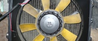
The pulley is not always considered an integral part of the generator, since it is mounted separately on an already assembled housing. The main task of a pulley is to transmit mechanical energy. As part of the generator, it is connected by a belt drive to the crankshaft and pump pulleys. Therefore, all three devices work in an inextricable connection with each other.
Operating principle of the unit and charge indicator lamp
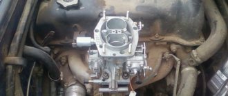
The operating principle of the generator 37.3701 and G222 are identical. The generator device converts the mechanical energy that appears when the crankshaft rotates into electrical energy. The resulting electricity is needed to power the on-board network and recharge the battery. Alternating current is converted into direct current with a power of 80 Amps thanks to a rectifier unit consisting of 6 diodes.
A three-level regulator maintains the voltage at the required level. After turning on the ignition, the voltage passes through the control lamp, reaches a three-level regulator, and then goes to the excitation winding.
This process can be clearly represented in the form of a diagram:
Generator wiring diagram
In the diagram, the main parts of the on-board network are marked with the following numbers:
- Battery.
- Generator set.
- Mounting block.
- Egnition lock.
- Voltmeter for measuring voltage.
- A lamp that monitors battery charging.
Power comes from three diodes, which are located in the rectifier unit. If, after turning on the ignition, the indicator light does not go out, this means that the battery is not sufficiently charged. In this case, it is necessary to check what voltage is in the on-board network. Technical characteristics of the generator: at a voltage of 13 V, the maximum current is 55/80 Amperes (video author - Vladimir Zagrivy).
Generator faults
Unfortunately, mechanisms have not yet been invented that would not fail under the influence of time and constant loads. The VAZ 2107 generator is designed for many years of operation, but in some cases this is hampered by minor breakdowns and malfunctions of its components.
You can identify problems with the generator without the help of service station specialists: you just need to carefully monitor all the changes that occur with the car while driving.
The charging indicator light on the instrument panel came on
In the interior of the VAZ 2107, there is a terminal for several signaling devices on the dashboard. One of them is the battery charging indicator light. If it suddenly lights up red, it means there is not enough charge in the battery or there is a problem with the generator. But the alarm does not always indicate a problem with the generator itself; most often the lamp goes off for other reasons:
- slipping of the generator belt drive - you will need to stop the machine and adjust the degree of belt tension;
- there is damage in the warning lamp relay, so it does not work correctly - it is recommended to “ring” the relay in the mounting block and, if necessary, replace it;
- breakage of contacts in the excitation winding is a more serious damage that requires removing the generator from the car, disassembling it and searching for a break;
- severe wear of the brushes in the brush holder - they will need to be replaced, which is quite simple;
- short circuit in the rectifier (most likely, one of the silicon diodes has burned out) - it is recommended to disassemble the generator, test the diodes and replace the failed element.
The battery is not charging
VAZ 2107 drivers often encounter this problem: the generator seems to be working properly, but there is no power to the battery. The problem may lie in the following malfunctions:
- the alternator belt has stretched - you need to check the degree of its tension or replace it with a new one;
- loosening the fastening of the wire tips - just tighten all the fastening connections and thoroughly clean the contacts and connectors;
- malfunction of the battery itself;
- Damage in the wiring - it is recommended to ring all the wires between the battery and the generator and replace the damaged areas.
The battery is boiling over
Battery boiling over is a sign that the battery does not have long life left. After this, the battery will not be able to function fully, so it will have to be replaced soon. However, so that the replacement does not lead to the same sad consequences, it is necessary to find the cause of the boiling, which may be:
- contamination of the contact between the ground and the housing of the generator regulator - cleaning of the contact is necessary;
- damage to the voltage regulator board itself - replacement of the board is recommended;
- defective battery - if the battery began to boil away immediately after replacement.
When driving there is noise and grinding noise from the generator
The generator has a rotating rotor, so it must make noise during operation. However, if these sounds become increasingly loud and unnatural, you should understand the cause of their occurrence:
- loosening the nut on the pulley - you need to tighten the nut and check the degree of belt tension;
- deterioration of the bearings - in this case, the driver may hear a loud grinding noise and even a howl while driving; it will be necessary to press out the old bearings from the shaft and install new ones;
- short circuit in the winding - the entire stator needs to be replaced;
- creaking brushes - it is recommended to clean the brushes from adhering dirt.
Video “Removing the generator from VAZ 2101-2107 models”
This video from Nikita Shurikov demonstrates how to remove a generator set from a VAZ classic with your own hands.
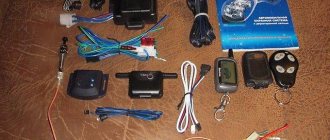
Depending on the year of manufacture of the car, the connection diagram for the VAZ-2107 generator may vary. Over the years, various devices have been added to the car, and electricity consumption has increased. If in the early 80s you could find a radio or (in very rare cases) a cassette recorder on cars, today the list is supplemented by central locks, alarm and security systems, and acoustics (subwoofers, powerful amplifiers).
Various types of devices help the driver - video recorders, navigators, inverters, chargers, pumps, etc. And they all consume electricity, and a generator helps replenish the charge, which charges the battery to the optimal level.
Generator check
Problems with the generator set can be avoided if the condition of this unit is periodically diagnosed. Checking the functionality of the generator gives the driver confidence that it is working properly and there is no cause for concern.
You cannot test the generator by disconnecting it from the battery while the engine is running. This is fraught with power surges and short circuits . The easiest way is to contact a service station specialist to check the functionality of the generator on a stand. However, convinced “seven guides” have long adapted to checking the G-221A on their own using a multimeter.
For diagnostics, you will need a multimeter of any type - digital or indicator. The only condition: the device must work correctly in both AC and DC measurement modes.
Operating procedure
Two people will be required to diagnose the generator's functionality. One of them should be in the cabin and, upon a signal, start the engine, the second should directly monitor the multimeter readings in different modes. The operating procedure will be as follows.
- Switch the device to constant current mode.
- With the engine turned off, connect the multimeter first to one terminal of the battery, then to the second. The network voltage should not be less than 11.9 and more than 12.6 V.
- After the initial measurement, start the engine.
- When starting the engine, the measurer must carefully monitor the instrument readings. If the voltage drops sharply and does not rise to operating condition, this indicates the exhaustion of the generator's life. If, on the contrary, the voltage indicator is higher than normal, then the battery will soon boil away. The best option is that when you start the engine, the voltage drops slightly and immediately recovers.
Video: procedure for checking a generator with a light bulb
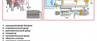
Connecting devices
The generator is connected in parallel to the battery. The relay regulator monitors the voltage level and controls the excitation current of the generator. Figure 1 shows a connection diagram for a 37.3701 generator with a built-in relay regulator.
Let's list the elements of the scheme:
- Battery.
- Diode "-".
- Additional diode.
- Generator.
- Diode "+".
- Stator winding.
- Regulator.
- Excitation winding.
- Capacitor.
- Mounting block.
- Charge indicator lamp.
- Voltmeter (not available on VAZ-2105).
- Ignition relay.
- Ignition switch.
Figure 1. Connection diagram for generator 37.3701 with built-in relay regulator.
Note that several electrical circuits have been developed for the “sevens”. They may vary. For example, the VAZ-2107 circuit with fuel injection is not suitable for Zhiguli cars that have a carburetor.
Voltage measurements are carried out with the engine idle and running. The tester switch is set opposite the 20 V mark. We measure the battery voltage before starting the engine. The numerical value will be 12-13 V.
After startup, the voltmeter readings will rise to 14.2-14.5 V.
Such indicators indicate the serviceability of the generator unit and charging circuit.
Generator set belt for VAZ 2107
The VAZ 2107 car was produced from 1982 to 2012. Initially, the model was equipped with a smooth drive belt (old model). Over time, the “seven” was modified several times and at the end of the 1990s, the generator began to work with a new type of belt with teeth.
The most popular among car owners are rubber products from the German company. These belts fit perfectly into the operation of a domestic car and serve for the entire period specified by the manufacturer.
The design numbers and sizes of the belts are indicated in the vehicle’s service book:
- 2101–1308020 (smooth surface), dimensions - 10.0x8.0x944.0 mm;
- 2107–1308020 (toothed surface), dimensions - 10.7x8.0x944.0 mm.
How to tension a belt on a generator
The operation of the generator, as well as the water pump, primarily depends on the correct tension of the belt on the pulley. Therefore, existing rules cannot be neglected. The belt is installed and tensioned in the following order.
- Place the assembled generator in place, lightly tightening the fixing nuts.
- Take a pry bar and use it to fix the gap between the generator housing and the pump.
- Place the belt on the pulley.
- Without releasing pressure from the pry bar, pull the belt onto the pulley.
- Tighten the top nut securing the generator until it stops.
- Check the degree of belt tension - the rubber should not sag, but it should not be too tight.
- Tighten the lower nut securing the generator.
What to do if there is no charge, weak charge (battery is discharged)?
If the battery of your VAZ 2107 is discharged, then one of three elements may be “to blame”: the generator, the voltage regulator, and the connections between them. Determining “who is to blame” can be very simple, even without additional devices. How this article will help.
We carry out testing using standard equipment
To monitor the operation of the generator on the “seven” there are two instruments: a voltmeter and a control light on the instrument panel. With their help, you can track the cause of your troubles.
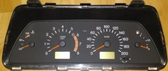
1) Turn on the ignition without turning on the starter and look at the warning lamp. It should shine at full intensity, as in the photo. The voltmeter needle, normally, stands on the white part of the scale (photo). Let's say everything is OK - go to point 2
The battery charge control lamp is on
Position of the voltmeter needle before starting the engine (ignition on)
The lamp does not light, the voltmeter needle remains at zero when the ignition is turned on.
Check fuse No. 10 in the mounting block. 99% of the time it will be burnt out. In this case, all other lamps on the instrument panel will also be de-energized. Replace it with the same one and test again. If the fuse burns out again, you need to look for the cause, that is, a short circuit. We check whether the wires from the generator are disconnected, whether the insulation is frayed somewhere, etc. Diagram 3 at this link
The lamp does not light up, the voltmeter needle shows normal
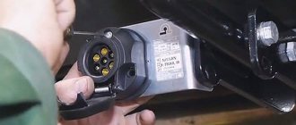
We check the wires on the generator to see if the wire has come loose from terminal “61”. If everything is normal there, you need to check whether there is a “plus” on this wire using a test lamp, an indicator screwdriver or a multimeter.
Terminal “61” of the VAZ-2107 generator
If there is a “plus” , we check the “tablet” (aka “chocolate”) and the generator.
There is no “plus” - you will have to remove the instrument panel and check the lamp. Replace the burnt out one. How to remove the panel, watch the video
2) Start the engine . The control lamp should go out, the voltmeter needle goes into the green sector and is located from the middle to the right edge (photo). If everything is so, then most likely the generator is working normally .
The voltmeter shows normal voltage (charging is present)
The lamp remains on or dims slightly
If you give it gas, it goes out at high speeds and lights up again when they decrease. The voltmeter needle is in the white sector and goes to the edge of the green when the speed increases. The generator output is faulty . The same conclusion if the lamp continues to light at any speed, and the voltmeter needle is in the white sector and even goes to red.
Voltage too low (motor running). Weak charge
3) If the generator seems to be working, but the battery is gradually discharging, we will perform another check. We start the engine, turn on the heater fan and low beam, take the key to “10” and, loosening the negative terminal of the battery, remove it. An idling engine (about 900 rpm) should not stall. If the engine stops, put the terminal back in place and start it again. While holding the speed at 1200-1500, remove the terminal again. Has the engine stalled again? Then turn off the headlights, leave the heater fan on and repeat the test. Now the engine with the negative terminal disconnected from the battery continues to run. output works, but does not produce the required current; it needs to be repaired.
Note! During such a check, it is better and safer to work together. You cannot disconnect the battery terminal without at least turning on the heater fan or other load. A voltage surge at the time of shutdown can “burn” the electronic elements of the ignition systems. You need to be especially careful on a car with an injection engine.
Differences in generator connection diagrams.
The VAZ 2107 charging scheme differs depending on the year of manufacture of the car, but not significantly. The difference lies in the presence or absence of a charge indicator lamp on the instrument panel, the method of connecting it, and the presence or absence of a voltmeter. But this only applies to carburetor cars. On cars with an injection engine, the circuit does not change and is exactly the same as on the first cars.
Charging diagram before 1986.
Let's consider the VAZ 2107 charging circuit with a control lamp that operates through a relay. It was used on cars produced until 1986. This circuit is characterized by the presence of a battery charge indicator lamp.
When the ignition is turned on, the plus from the lock through fuse No. 10 “Instrument panel, direction indicators” is supplied to the relay of the battery charge indicator lamp to the contact and output of the coil. The second terminal of the coil is connected to the central terminal of the stater, where all three windings are connected. The relay contacts are constantly closed, the control lamp lights up. When the engine is running, when the generator begins to produce current, an alternating voltage of about 7V appears on the windings. Current begins to flow through the relay coil and the armature is attracted, opening the contacts.
At the same time, current flows to the output of generator No. 15 through fuse No. 9. The excitation winding receives power through the brush voltage regulator.
Connection diagram after 1996 (carburetor engine).
The VAZ 2107 charging circuit differs from the previous one only in the absence of a warning lamp relay. Excitation in this case occurs in the same way as in the previous case. The presence and level of charge is determined by a voltmeter on the instrument panel.
Charging circuit for injection engines.
This scheme is the same as on other VAZ models. The difference from the previous ones is in the method of exciting and monitoring the health of the generator. Monitoring is carried out using a warning lamp and a voltmeter on the instrument panel. Through the charging lamp, the initial excitation of the generator is also carried out at the moment of operation. During operation, the generator operates autonomously, that is, excitation comes directly from output 30 of the generator.
When the ignition is turned on, power through fuse No. 10 is supplied to the charging lamp in the instrument panel. Then through the mounting block to output 61 of the generator. The voltage regulator receives power through three additional diodes, and through it the excitation winding of the generator. At the same time, the control lamp will light up. When the generator starts working, a voltage higher than the battery voltage will appear on the plates of the rectifier bridge. In this case, the control lamp will go out, since the voltage on the side of the lamp on the additional diodes will be lower than on the side of the stator winding and the diodes will close. If the control lamp lights up when the generator is running, then one or more additional diodes are broken.
What to do if the battery is boiling
The lamp goes out, the voltmeter needle goes to the right into the red sector, and there is a sharp “chemical” smell in the cabin. At idle, the needle is in the green sector, but as soon as you accelerate, it goes all the way to the right. This indicates that the voltage regulator (chocolate) has failed . If this happens, moving on is more expensive! All the electrical equipment of the car may burn out, and the battery will get damaged, the electrolyte will “boil”, the plates may become warped. To get to the repair site, you can temporarily turn off the generator by removing the wire from terminal “61” of the generator. You can drive for quite a long time on a good battery, just don’t forget to turn off unnecessary electrical appliances - heater fan, heated rear window, radio, etc. Headlights or running lights will have to be left.
Voltage too high (overcharge)
This article describes a simple way to determine if the alternator, voltage regulator, or connections between them are faulty. How to repair all this in the next article .
I have a VAZ 2107 injector, the voltmeter needle goes to the left to red, while charging is normal both at idle and under load
Sergey! I've seen this happen; all the dial gauges were lying. Replaced the dashboard assembly. The reason was found out of curiosity - broken diodes.
VAZ 2107 injector, the generator produced 12.5 V, the lamp is on when the ignition is turned on, the voltmeter is in the white zone, when the lamp is turned on, the lamp goes out, the voltmeter remains in the white zone, I changed the tablet and the diode bridge, it gave 13.2 V, a day later it was 12.5 again
Unfortunately, the quality of spare parts today is simply terrible. Most likely the diode bridge has failed again. Sometimes, according to acquaintances from the car service center, they go through several pieces until it “takes root.” Or you can try to buy a used generator at a salvage yard.