Models, characteristics, location
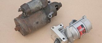
The designers did not borrow a starter from other VAZ models, but made a new one - for Oka engines. The impossibility of unifying starters for owners of this small car often results in problems, since the “native” starter is not a particularly reliable unit.
It is noteworthy that Oka’s power electric motors were produced by several manufacturers. The most common is the unit with the factory index 39.3708 (KZATE Samara plant), which we will consider in the future. Also, the VAZ-1111 was equipped with Belarusian-made components (1111-3708010-5) and Slovenian ones - AZE-1517.
The main characteristics of model 39.3708 are as follows:
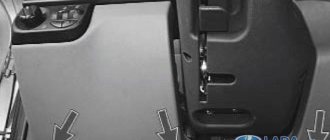
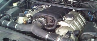
This unit is mounted on the left side of the engine (in the direction of travel) above the gearbox, and the thermostat housing is located above it. Fixation is carried out with only two fasteners - a bolt and a nut, with which the starter is attracted to the clutch housing. This arrangement is convenient because you can dismantle the unit from the car without removing anything additional.
Standard starter for VAZ-1111
This car is equipped with a unique starter, a little similar to the device from the VAZ-2108.
The electric motor is specifically designed for Oka engines, which often leads to problems. The original starter is not particularly reliable, and when it fails, difficulties begin with unification. The original electric motor has a left-hand rotation and a single-support armature that is smaller than the standard ones. The starter is installed on the left side in the direction of travel, directly above the gearbox. Above the device is the thermostat housing. The starter is secured with two thick bolts and nuts on the protrusion of the clutch mechanism. This is a convenient location, which makes it possible to easily remove the unit from the car - there is no need to dismantle a lot of parts, as on foreign cars.
One of the main disadvantages of a native starter is the absence of a “dome” - an additional reference point for the anchor. Instead, the support function is performed by a recess in the engine block with a bushing. It is she who often fails.
Starters for Oka cars are produced by several manufacturers. The most common Samara model is KZATE 39.3708. It is almost impossible to find it separately in the markets, but you can purchase it in Oka spare parts stores for a crazy price - 12,500 rubles. Recommended retail price - 4 thousand rubles.
BATE models with article number 1111-3708010-5 and Iskra AZE-1517 are also in demand. Belarusian devices are cheaper - 3.5-4 thousand rubles. BATE currently produces many parts for its starters, so repairs are also possible:
- drive 2111.3708600;
- solenoid relay - 426.3708800-10;
- rotor - 2111.3708200;
- brush holder or traverse - 63.3708311.
Analog starters can also be installed on Oka. For example, from a VAZ 2110. However, in this case, modifications will have to be made. In particular, the launch unit for the “ten” is equipped with a “dome”. Therefore, you will have to upgrade the clutch housing, disassemble the transmission, etc. The surfaces of the “dome” will need to be sanded with a grinder, reducing the diameter. Mounting lugs - cut off. Remove the partition from the inside of the crankcase and grind the adjacent surfaces.
| KZATE 39.3708 | BATE 1111-3708010-5 | Iskra AZE-1517 | |
| power, kWt | 1.5 | 1.4 | 0.9 |
| Voltage, Volt | 12 | 12 | 12 |
| Number of teeth | 9 | 9 | |
| Gear module | 2600 | 2100 | 1800 |
| Gear rotation direction | the opposite | left | ACW |
| Weight, kg | 3.7 | 4.7 | 4 |
| Capacity, Ah | 66 | 55 | 50 |
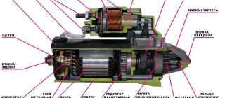
Design
The starter on the Oka is a commutator electric DC motor. Its main components are:
All elements are assembled into a single structure and secured with coupling bolts.
The stator due to the passage of electrical energy through its windings, ensures the emergence of an electromagnetic field. The second magnetic field is created by the armature winding. Electric current is supplied to it through graphite brushes to the commutator, to the plates of which the ends of the armature winding are soldered. The magnetic fields generated around the windings lead to the rotational movement of the armature.
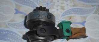
On one side of the armature shaft there are splines on which a bendix is mounted, consisting of a gear and an overrunning clutch. Bendix has the ability to move along the shaft, and due to the spline connection, rotation is transmitted to it.
The Bendix gear is designed to engage with the crankshaft flywheel and transmit rotational motion to it. By default, the gear is not engaged with the flywheel and there is no interaction between the engine and the power electric motor.
The task of the overrunning clutch is to interrupt the transmission of rotation after starting the power unit. Even at minimum speeds, the rotation speed of the crankshaft is higher than the starter speed, so after starting the engine, reverse rotation is transmitted - from the flywheel to the electric motor. engine (until the gear is disengaged), which significantly reduces the service life of the starter. To prevent this negative effect, the gear interacts with the armature shaft not directly, but through a roller clutch, consisting of two cages and rollers placed between them.
The essence of the clutch is this: while the rotation speed of the starter armature is higher than that of the flywheel (the engine is not running), the rollers “jam” the cages among themselves, thereby transmitting rotation to the gear. As soon as the engine starts and the flywheel accelerates, one of the races moves relative to the second and the rollers “wedging” occurs, due to which the transmission of rotation from the gear to the armature is interrupted.
The movement of the bendix along the shaft splines is carried out by a retractor relay installed on the starter housing. This unit is also “responsible” for supplying electricity to the electric motor windings.
The peculiarity of the starter is that the gear is first engaged, and only after that the electric motor is turned on. And all this is provided by the retractor relay.
Solenoid relay - located on the starter
The relay consists of a housing with windings located inside, a contact disk and power contacts (“nickels”), as well as an armature that engages with a fork that interacts with the bendix.
Characteristics of the starter on Oka
First, let's look at the main functional features of starter devices. Let's start with the design and principle of operation.
Location and purpose
The starter unit is a device used to convert electrical energy into mechanical energy, which is necessary to start the engine. In Oka cars, this mechanism is located under the cooling system thermostat. It is secured with a screw and nut on the clutch housing.
Design and principle of operation of the unit
The mechanism body contains the poles of the excitation winding, which are fixed with special screws. Three of these windings are series connected and one is a shunt winding. The entire structure is secured by two housing covers, secured with screws. On the back cover there is a special brush mechanism with four brushes.
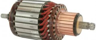
In the body itself there is an armature - this is a shaft with an installed core with a winding, its ends are brought out to the plates of the commutator device. The latter is an end-type part. There are splines on the front part of the anchor element; the mechanism drive, which, in turn, is equipped with internal splines, moves along them. The drive itself is directly fixed to the halyard using a special bushing installed on top of the locking ring, which, in turn, is located on the groove of the shaft.
A traction relay is installed on the upper part of the housing, in particular the lid. This element structurally consists of a housing with winding elements, a core, as well as a cover and a return spring. On the relay cover itself there are screws that also serve as the power contacts of the element. There is also a contact plate designed for closing power contacts.
The relay itself is equipped with two windings - a pull-in winding and a holding winding, and an additional contact is installed in its cover, which is used to power them. Voltage is transmitted to it from the ignition switch when the driver tries to start the engine.
Photo gallery "Main components"
As for the drive, or as it is commonly called, the Bendix, this element is a freewheel, and at one end there is a drive gear. The design of the starter mechanism provides for the presence of a coupling, which is necessary to supply torque in one direction from the unit to the power unit. When the unit is started, the mechanism will be disconnected from the motor. The purpose of the relay is to feed the gears of the drive element into connection with the flywheel.
Briefly about the principle of operation:
- The driver turns the key to the Start position.
- The mechanism relay supplies power to the winding elements, and then to the windings of the traction relay.
- As a result, an electromagnetic field is formed, which promotes retraction of the core. When this element is retracted, a drive lever is pulled behind it, the purpose of which, as stated above, is to engage the gear of the device with the flywheel.
- When the core is fully retracted, as a result of the movement of the plate, the contacts close, which leads to the supply of voltage to the windings of the electric motor. At this moment, the winding is also de-energized.
- When the power unit is started, the overrunning clutch comes into operation, which breaks the supply of torque from the power unit to the anchor element. Thus, it prevents damage to the latter. When the engine is started, the key will exit the Start mode, which will open the contacts on the relay. The heart element returns to its original position.
Which node is suitable?
Many car owners are interested in the question - what can make a starter suitable for Oka? Since standard devices are not particularly reliable and our compatriots are often faced with the need for repairs, we have to look for analogues for installation. The best option is the mechanism from Katek for the VAZ 2110; it has identical fastenings (the author of the video is the Expert R channel).
Connection diagram. Principle of operation
The starter is powered from the on-board network as follows: a large cross-section wire is laid from the “positive” terminal of the battery to one of the contacts of the solenoid relay. From the second contact of the relay there is a bus to the brush holder and stator windings. This circuit is the main one for powering the electric motor, but there is a break in the relay, which prevents the constant supply of current to the windings.
From the same “positive” terminal there is another wire, passing through the additional relay, the ignition switch and leading to the solenoid relay. The task of this circuit is to power the relay windings.
To turn on the starter, the driver must set the key in the lock to position “2”. Thus, it closes the power circuit of the solenoid relay, and current flows to its windings. As a result, a magnetic field arises, which leads to the movement of the relay armature - it is “pulled” into the housing.
Moving inside the body, the anchor pulls the fork along with it, and it moves the Bendix along the splines of the armature shaft, engaging the gear with the flywheel.
At the same time, the anchor pushes the rod on which the contact disk is fixed. Having reached the stop, this disk is pressed against the “nickels” of the power contacts, as a result of which the electrical power supply circuit is closed. engine, and it begins to rotate, and the gear will already be engaged.
After starting the Oka motor, the clutch is activated, preventing reverse rotation.
By returning the key to position “1”, the driver opens the relay power circuit, the return spring “pushes” the armature. Moving back, it stops acting on the rod of the contact disk, due to which the electrical power supply circuit is opened. engine. At the same time, the anchor pushes the fork, and it disengages the bendix.
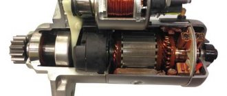
Starter of the OKA VAZ-1111 - 1113 car
Starter of the OKA VAZ-1111 - 1113 type 39.3708 : 1 - overrunning clutch; 2 - restrictive ring; 3 - drive gear; 4 - drive side cover; 5 — drive lever; 6 — relay anchor; 7 - relay holding winding; 8 - relay pull-in coil; 9 — contact plate; 10 — relay cover; 11 — contact bolts; 12 — casing; 13 - collector; 14 — back cover; 15 — brush; 16 — body; 17- pole; 18 - anchor.
Starter type 39.3708 is a four-brush DC electric motor with mixed excitation and an electromagnetic two-winding traction relay.
Technical characteristics of starter 39.3708:
Rated power, kW 0.9 Current consumption at rated power, A, no more than 230 Current consumption in the inhibited state, A, no more than 310 Current consumption in idle mode, A, no more than 60
Four poles with field windings are secured in the starter housing with screws:
three series (connected in series) and one shunt. The body and covers are secured with two bolts. The anchor is with an end commutator. The rear end of the armature shaft rotates in a metal-ceramic bushing pressed into the cover, and the front end rotates in a bushing pressed into the clutch housing. (When installing the starter, make sure the bushing is in place.) The drive shaft has a freewheel (overrunning clutch) with a drive gear. It transmits torque in only one direction - from the starter to the engine, separating them after the engine starts. This is to protect the starter armature from damage due to excessive speed. The traction relay is used to engage the drive gear with the ring gear of the engine crankshaft flywheel and turn on the power to the starter motor. When the ignition key is turned to the “starter” position, voltage is supplied through an additional relay type 113.3747-10 to both windings of the traction relay (retracting and holding). After closing the contacts of the traction relay, the retractor winding is turned off. The operating voltage of the traction relay should be no more than 9 V at (20±5)°C. If this is not the case, there is a fault in the relay or actuator. The serviceability of the drive is determined by inspection after disassembling the starter. The faulty relay is replaced. On some vehicles, a starter type 1111.3708 with a rated power of 1.0 kW is installed with excitation from permanent magnets (it does not have poles with windings). Six segment magnets are located on the inner surface of the starter housing and are held in place by two plastic holders located near the covers. The covers are secured with two pins, the latter also securing the pole holders.
OKA starter parts with codes:
1111-3708020 Lever 1111-3708043 Cap 1111-3708100 Housing assembly 1111-3708110 Series pole coils 1111-3708160 Parallel pole coils 1111-3708200 Armature 1111-3708300 Cover 1 111-3708340 Brush with tip 1111-3708350 Insulated brush 1111-3708401 Cover 1111 -3708600 Drive 1111-3708800 Starter relay 2101-3708418 Cover plug 2101-3708676 Gear travel limiter 2101-3708678 Retaining ring 2108-3708081 Tie bolt
Main malfunctions and why the starter does not turn?
Malfunctions of the Oka starter, as well as the power electric motors of cars, are divided into two categories - mechanical and electrical. The first includes:
The most common mechanical failure is wear of the support bushings, which subsequently becomes the cause of other breakdowns. Due to significant wear of the bushings, the position of the armature and, accordingly, the bendix are disrupted. As a result, it is more difficult for the gear to engage, the wear rate of the teeth increases, and they may crumble.
Electrical faults include:
To this category of breakdowns you can also add problems with the power circuits of the electric motor and relay.
Malfunctions of the Oka starter manifest themselves in different ways:
If such signs occur, the unit should be repaired.
Unit dismantling, disassembly
Removing the starter on an Oka is not a difficult operation due to its relatively convenient location. The work algorithm is as follows:
Next, the unit is disassembled and diagnosed.
First, the retractor relay housing is dismantled, for which you need to unscrew two nuts. When dismantling the housing, the relay armature will remain in place, since it is hooked onto the fork with an eye. If necessary, we also remove the anchor.
To disassemble the electric motor itself, unscrew the two coupling bolts, after which you will be able to remove the back cover and pull the brush holder off the commutator. After this, you can remove the stator housing with the winding.
For further disassembly, remove the retaining ring from the front of the armature shaft and pull out the armature. All that remains is to pull out the fork axle and remove it along with the bendix.
Mechanical faults can be identified visually by carefully inspecting each component part. If signs of severe wear or damage are detected, the part should be replaced.
As for electrical faults, they can only be identified by testing the windings. For such a check, it is better to contact an experienced electrician.
Device and electrical diagram
The starter from KZATE has a simplified design of a conventional commutator electric motor. The main details are:
- field windings;
- rotor;
- brushes;
- traction relay;
- overrunning clutch;
- covers;
- fork.
Article on the topic: Starter Vaz 2112
All elements are assembled in a housing, the covers are secured with studs and bolts. The starter on the VAZ 1111 is powered from the on-board network. The scheme is implemented as follows. The control cable is routed from the battery to one of the contacts of the traction relay. Next, from the retractor there is a bus to the starter brushes and windings. It turns out the main chain, but there is also a break in it. It is needed to eliminate the constant supply of voltage to the windings.
The additional power circuit starts from the positive terminal through an additional relay, the ignition switch and closes at the solenoid relay. The task is to provide power to the relay windings.
Starter for OKU: what cars is it suitable for?
One of the significant disadvantages of the Oka starter is the absence of the so-called “dome”. In those nodes where it is present, the “dome” acts as a second reference point for the anchor. In Oka, due to the absence of this component, the second support for the shaft is a recess in the engine block. The support sleeve is also installed in it. Therefore, if the bushings wear out - and this is the most common malfunction - replacing them becomes a serious problem for the owner.
OKA starter catalog number: 391.3708 - if you decide to install the same one.
One of the options for solving problems with bushings is to install a starter from another car on the Oka. As a replacement, you can use the VAZ-2110 starter, which has a “dome”.
But in order to install a “ten” starter, you will have to make certain modifications to the unit itself, as well as the clutch housing, for which you will have to remove not only the starter itself from the car, but also disassemble the transmission - remove the gearbox, clutch and dismantle the clutch housing.
To install the VAZ-2110 starter on the Oka, you need to use a grinder. machine to grind the surface of the “dome”, thereby reducing its diameter. You will also have to cut the mounting lugs.
In the crankcase, you need to cut out the partition from the inside and grind the surfaces adjacent to the mounting hole.
All these modifications are aimed at ensuring that the new unit fully “fits” into the crankcase hole.
Some craftsmen, instead of the “native” starter on the Oka, even installed a unit from a VAZ of the classic family, the same VAZ-2106. But in this case, the improvements were significant, since the starter from the “classic” is larger. The installation issue in this case was resolved by using an adapter plate.
Replacement and size of bushings
Those car enthusiasts who have no desire to redo anything to eliminate armature play will have to change the bushings.
There will be no problems with the interior, since it is installed in the back cover and it is not difficult to get it out after removing and disassembling the starter. But the bushing, which is installed in a recess in the block, is difficult to get.
There are several options for extracting it:
If everything is clear with the first two methods, then the third should be considered in more detail. The method is based on the property of a liquid not to compress.
The extrusion technology is quite interesting - we select a rod whose diameter exactly matches the hole in the sleeve. Next, fill the bushing completely with grease (for example, “Solidol”). Then we insert the rod into the hole and hammer it inside. Due to compression, Solidol will penetrate under the bushing and begin to squeeze it out.
After removing the worn bushing, we install it in its place with a new one, after which all that remains is to put the starter in place.
Why does the starter bushing break on the eye?
Tell me, who thought of placing the starter bushing in the clutch housing?!
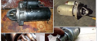
It all started on a frosty morning when I was trying to start the car. On the 3-4th start of the engine I heard a terrible grinding noise. He used a screwdriver to bend the timing case, put a passerby behind the wheel and asked him to turn the starter. The belt moved slightly and stood still, and the grinding noise came from the starter area. So far it hasn't told me anything. I didn’t torture the car further, but called my friend, who lives on the floor below, and asked me to ride me on a cable to the nearest service station, where his friends worked. The guys there turned out to be smart, Okushki didn’t get scared (as in most car repair shops in Yekaterinburg), but immediately removed the starter and showed me the reason for the grinding noise:
We removed the bushing fragments by removing the casing from below. Then they inserted a new bushing, which went in too easily, and the repair one (larger in size) did not go in at all. Therefore, we decided to put this one on cold welding.
We warmed it up with a special hairdryer and put the starter in place. A couple of attempts to start the engine, and voila! We hear the familiar grinding noise again. It was too late. There was no time to poke around any further, so the guys helped me push it, and I drove to the house. The next day, after disassembling the starter at home, I saw a miserable picture. The shaft itself was walking along its axis, there was crumpled cardboard and dirt inside. When I tried to clean everything and reassemble it, the play disappeared, but the next time I tried to insert the turned repair bushing and this starter into place, it did not produce any results. Bendix hit the hub with force and cracked it again.
I saw only one way out - buy a new starter and not suffer. Moreover, from all subsequent experiments, the already broken clutch housing, the price of which reaches 6,000 rubles, could have suffered. I started it again from the pushrod and went to Olmi, where I bought a brand new gear starter.
Since the hole in the crankcase was oval, I had to carefully file the repair sleeve so that the outside would be shaped like a hole and fit tightly into place. I installed the new starter and started the engine! I didn’t regret buying a starter, because it spun the flywheel so powerfully that it now started the engine in 1.5-2 seconds. At intervals I turned off the car and started it again. No grinding was heard, but some extraneous sound was sometimes heard. Just for fun, I removed the starter and looked at what was wrong with the bushing:
The bushing was slightly chipped, but it stayed firmly in place. Now there's another problem. To the left you can see that a tooth has been torn off on the flywheel crown! I planned the repair for this weekend, but for now I’m driving like this. I heard the grinding sound only once, when the extracted tooth stood right next to the bushing. To start, I pushed the car into gear. The “sick” tooth went to the side, and I started up calmly from the starter.
The starter cost 2600, the rest I spent on bushings + 200 rubles. to the guys from the service.
See the further adventures of the stupid bushing soon in my logbook. I'm also looking for advice in the comments, thanks in advance
There are quite a lot of weak points in the engine of the OKA car. Because of them, some parts require some improvement or significant design changes. One of them is the front OKA starter bushing, pressed into the gearbox housing. It is a support that supports the front toe of the rotor.
Its main problem is that it is made using technology taken from powder metallurgy. In fact, it consists of chips of graphite and bronze that have been pressed. Of course, manufacturers came to this technology solely to reduce the cost of production.
But, unfortunately, such an OKA starter bushing is incredibly fragile, which is why it lasts a very short time, constantly breaking. The worst consequence of such a breakdown is that because of this the entire mechanism is deprived of support and then fails.