Checking the fuel pump activation circuit
If the fuel pump does not turn on when the ignition is turned on (its operation can be checked by ear), there may be a malfunction of both the fuel pump itself and its activation circuit. We begin checking the fuel pump activation circuit by assessing the integrity of fuse F111 (15 A), located in the mounting block in the passenger compartment.
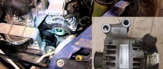
We replace the faulty fuel pump fuse with a new one, first checking to see if one of the terminals of the fuse socket is shorted to ground. A malfunction in the fuel pump switching circuit may be caused by damage to the pump relay R19 in the mounting block. To check the relay...
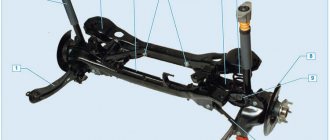
...remove it from the mounting block and replace it with a known good one. For this purpose, you can use the horn relay R2. If the fuel pump turns on with the newly installed relay, the fuel pump relay has failed and must be replaced. However, the most likely reason for the fuel pump to turn off is the activation of the fuel supply system emergency switch. Under operating conditions, if a wheel (especially the front left one) gets into a pothole on the roadway or hits an obstacle, as well as even a slight collision with another vehicle, the negative wire of the fuel pump is disconnected.
The switch is located behind the driver's door sill trim. It can be switched to a closed state by pressing it with a finger through a hole in the lining.
By removing the upholstery, you can check the functionality of the switch
Having disconnected the connector, we close the contacts of the wire block with a piece of wire. If power supply to the fuel pump is restored, the switch is faulty and must be replaced.
Prevention measures
What you need to know about the electrical network:
- If you carry out wiring repairs, it should be carried out exclusively with the on-board network de-energized.
- Connecting and disconnecting the battery is only possible with the ignition off.
- If you diagnose electrical circuits, any short circuits are excluded, since this can contribute to the failure of the equipment as a whole.
- When replacing fuses, use only parts specified by the vehicle manufacturer. If the elements are designed for higher current, they should not be used, like any other homemade fuses.
- To prevent a short circuit when replacing a fuse, it is prohibited to use any metal tools to dismantle and install them.
- When the power unit is running, the battery cannot be disconnected, as this will damage the voltage regulator and other components of the electrical circuit.
- When diagnosing a generator diode bridge, you cannot use a megohmmeter that is powered by more than 12 volts. In principle, increased voltage is not recommended for diagnosing system components.
- If you are welding elements of a vehicle body, then to do this you need to disconnect the battery, as well as the generator device. In addition, if welding is carried out without dismantling the body element, it would not be superfluous to turn off the power to the electronic control unit. If the ECU and alternator fail, it will result in large financial losses.
- When the engine is running, do not touch the wiring of the ignition system under any circumstances.
- Clean the battery terminals and terminals from time to time.
Shop
Skip to content
×
- Car service in Samara
- Photos of our works
- Price list
- Chip tuning ADACT
- Chip tuning Ayashev
- Chip tuning Beletsky
- Chip tuning Paulus
- Chip tuning MotorSoft
- Chip tuning in Samara
- Ford diagnostics
- Ford firmware
- PowerShift Repair
- Editor As-Built
- Electrical circuits
- SYNC update
- SYNC navigation
- Unlocking the radio
- Additional options Ford
- Online store
- FORD spare parts
- Ford spare parts catalog
- Catalog of spare parts for maintenance
- Equipment installation
Ford Focus 2014-
Fog lights
- SYNC II
- Rear View Camera
- Front parking sensors
- Cruise control
- Center speaker
- Autostart
- Cruise control
- Daytime Running Lights
- Rear parking sensors for Ford Kuga 2
- Hood shock absorbers for Ford Focus 2
- Ford Focus 2
What is included in the electrical circuit?
The electrical circuit of Ford Focus 1, 2, 3, 4, Ford Transit, Ford Scorpio cars includes many different components. The main components that power the electrical network are, as is known, the battery and the generator device. The ignition system is designed in such a way that the spark to ignite the combustible mixture is transmitted through high-voltage wires. Below you can find diagrams and designations of the main components.
Like any other car, Ford Mondeo 1, Focus 1, 2, 3, 4, restyling is equipped with a fuse box, the elements of which allow you to protect the car’s electrical equipment from power surges. But in addition to the main power supply, Focus 4, 3 or any other is also equipped with another unit in which relays are installed.
Electrical diagram of the block with relay
Relay designation
Common faults
Below are the main malfunctions that appear in the operation of the electronics of Ford Focus 3, 4, 2, 1:
- On these cars, the cables in the tailgate lid often break off. The problem is solved by removing the plastic trim and replacing the electric lock.
- Models 1, 2, 3, 4 suffer from the “disease” of failure of license plate lamps. As a rule, the main reason for the appearance of a defect lies in the rather poor sealing of the lighting sources, so when installing the lamps, everything must be done correctly. In addition, when purchasing, you should give preference to higher quality devices. Today you can find five types of light bulbs on sale from different manufacturers.
- Both the first and second Focuses, as well as other models, often suffer from such a problem as failure of the electric windows, especially in difficult climatic conditions. If this happens, the only way out is to remove the fuses from the installation socket for 10-20 minutes and then install them back. After installation, the window regulators must be raised all the way up, while the control button must be held for several seconds. If such actions do not solve the problem, you can try to dismantle the gear with the Hall sensor and rotate it 180 degrees (video author - SPN).
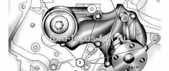
Generator
Generator Ford Focus 2: 1 — contact bolt; 2 — generator connector; 3 - casing; 4 — tie rod; 5 — back cover; 6 — front cover; 7 - pulley
When the generator is running, the battery is charged. The vehicle is equipped with a starter battery with a capacity of 60 Ah. The generator is a synchronous AC electrical machine with a built-in rectifier unit and voltage regulator. The generator pulley is driven by a poly V-belt from the auxiliary drive pulley. The stator and generator covers are secured with four studs. The rotor shaft rotates in ball bearings installed in the generator covers. The bearings are closed type and the lubricant contained in them is designed for the entire service life of the generator. The rear bearing is pressed onto the rotor shaft and is mounted in a plastic sleeve in the rear cover. The front bearing is installed in the front cover and covered with a pressure plate; the bearing has a sliding fit on the rotor shaft. The generator stator contains a three-phase winding. The ends of the phase windings are soldered to the terminals of the rectifier block, consisting of six silicon diodes (valves) - three “positive” and three “negative”, pressed into two horseshoe-shaped aluminum holder plates in accordance with the polarity (positive and negative on different plates). The rectifier unit is mounted on the back cover of the generator. The field winding is located on the generator rotor, and its leads are soldered to two copper slip rings on the rotor shaft. Power is supplied to the excitation winding through two brushes, which are installed in the brush holder. The brush holder is structurally combined with the voltage regulator and is mounted on the back cover of the generator (under a plastic casing). The voltage regulator is a non-separable unit; if it fails, it is replaced assembled with the brush holder.
The negative side of the battery should always be connected to the vehicle ground, and the positive side to the generator terminal. Reverse connection will lead to breakdown of the generator rectifier diodes.
When operating the generator, do not
disconnect the battery, as the resulting voltage surges can damage the electronic components of the circuit.
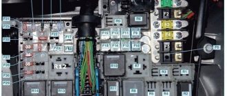
Fuse diagram and location for Ford Focus 2
Check whether all the buttons work, you can check, for example, by turning on the interior lighting mode, in which the light comes on when any door is opened. Also check the trunk lock contact, which transmits information to the unit about its closing. If you have no experience, it is better to contact a car service. F F48, 20A - backlight during daylight hours.
F F47, 15A - windshield washer pump, heated washer nozzles. If your washer stops working, check the fluid level in the washer reservoir. Perhaps the pump itself has stopped working and needs to be replaced.
Fuse. Ford Focus2. Replacing the fuse. The bc keeps going off. The clock is lost
The jets could become clogged or the liquid in the channels of the windshield washer system could freeze in the cold season. F F57, 10A - sound signal of an autonomous alarm siren, electric folding of side mirrors.
If the gas pedal does not work, check the 2 position sensors installed in its base, as well as the wiring to the electronic unit and to the throttle valve unit. The gas pedal may also not work due to a malfunction of any of the units or sensors. Read more about the electronic gas pedal. F F38, 10A - high beam in the right headlight.
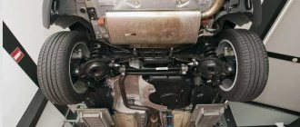
Disassembly of the interior, location of wires and equipment units.
To access the fuse box, remove the soft protection. Why do you need to unscrew the 2 plastic nuts. Then we turn the 2 clips securing the block and lower it.
We remove the left part of the torpedo and the steering column trim.
Installation location of the siren, hood switch and temperature sensor.
The wire under the hood can be pulled along the standard braid.
Email diagrams, connection diagrams, pinouts, etc.
from Russian_Mouse on GEM (fuse box in the cabin)
Using the first digit of the chain number, you can get some more information from this table (source):
You are wrong, here is the information from ETIS:
In a communication system module (data bus system), modules of different systems are connected to each other via one or more wires.
The data bus system exists to transfer data between connected modules, as well as between connected modules and the global diagnostic system (WDS).
Instead of simple ON/OFF commands, complete data blocks are transmitted in the data bus system. Such data blocks contain, along with the actual information, also data on the addresses of the modules being accessed, the size of the block, as well as information to control the contents of each individual data block.
Data bus systems offer the following advantages:
simple data exchange between modules via a standardized protocol fewer sensors and connectors improved diagnostics possible lower cost Via a standard 16-pin connector (DLC) WDS (connects) to various data bus systems and power supply. The signal is transmitted through the DLC when programming the module.
If one or more wires of the data bus system are broken, or there is a short circuit to ground or voltage appears, communication between the modules and the WDS is disrupted or disappears completely.
To restore communication with each other, the modules of individual systems must communicate in the same language. This language is called a protocol.
Ford currently uses four different data bus systems. Depending on the vehicle model and its equipment, all three systems are used. Each data bus system has its own protocol.
Data bus systems:
Standard Corporate Protocol (SCP) bus. This bus has two twisted wires. The bus serves for communication between the powertrain control module (PCM) and the WDS via the DLC. To program the PCM, depending on the engine brand and year of manufacture, a third cable, the ACP bus, is used. This bus is used exclusively in conjunction with the SCP bus. bus standard ISO 9141 of the International Organization for Standardization. This bus consists of a separate wire and serves exclusively for communication between the modules and the WDS. The data from various fault memory devices is read via the ISO 9141 standard bus. LIN (Local Interconnect Network) is a standard for cost-effective communication between smart sensors and vehicle actuators. The control subnetwork (LIN) is widely used where the range and versatility of the CAN bus is not required. The LIN specification contains the LIN protocol, a unified format for describing the overall LIN network, and the interface between LIN and the application. A LIN consists of a LIN master module and one or more LIN execution modules. To control access to the LIN bus, it uses the “Master-Slave” principle. The decisive advantage of this principle is that the execution module requires few resources (CPU performance, ROM, RAM) to operate the bus. The master module is implemented in a control module or gateway, which has the necessary resources for this. Any communication is initiated by the master module. Therefore, the message always consists of a header, which is created by the master module, and a response from the execution module. Data transfer speed is up to 20 Kbps. The LIN master has information about the time sequence of all transmitted data. This data is transmitted from the corresponding LIN execution module (eg ultrasonic sensors) if requested from the LIN master. LIN is a single-wire bus, i.e. Data is transmitted through only one cable core. Usually the supply voltage is supplied through the same cable. The mass of the supply voltage is also the mass of the data transmission line. The LIN bus does not use termination resistors. Controller Area Network (CAN) bus This bus consists of two twisted wires and operates in series (data is transferred one after another). The bus is used for communication between modules, as well as for communication between modules and WDS. The modules are connected to the bus in series. New modules can be easily connected here without changing the cable routing. The transmitted data is received by each module connected to the CAN (Control Area Network). Since each data packet has an identifier, which, along with the content designation, also sets the priority of the message, each module can determine whether the data is important for the information processing itself. Thanks to this, several modules can simultaneously work with one data packet and receive data. This ensures that important data (eg from the anti-lock braking system (ABS)) is sent first. Other modules can transmit data to the data bus only if the information arrives with high priority. To ensure high noise immunity, two load resistors with a resistance of 120 Ohms are installed on the CAN bus. These resistors are installed in the first module connected to the CAN bus and the last module connected to the CAN bus, and are used to eliminate interference, as well as to remove voltage peaks. To ensure reliable operation of the data bus system, the modules must be connected with a built-in load resistor.
What is included in the electrical circuit?
The electrical circuit of Ford Focus 1, 2, 3, 4, Ford Transit, Ford Scorpio cars includes many different components. The main components that power the electrical network are, as is known, the battery and the generator device. The ignition system is designed in such a way that the spark to ignite the combustible mixture is transmitted through high-voltage wires. Below you can find diagrams and designations of the main components.
Like any other car, Ford Mondeo 1, Focus 1, 2, 3, 4, restyling is equipped with a fuse box, the elements of which allow you to protect the car’s electrical equipment from power surges. But in addition to the main power supply, Focus 4, 3 or any other is also equipped with another unit in which relays are installed.
Electrical diagram of a block with a relay Relay designation
It will not be possible to start the engine without the ignition system, so we suggest that you familiarize yourself with the diagram of its connection and the designation of the main components.
Ignition system Ford Focus 1,2 3, 4
Also worth mentioning is the ECM - the electronic engine control system.
Engine control system and designation of main components and elements
An equally important point that any focus guide should be familiar with is the connection diagram for the generator device. As stated above, a lot depends on the functioning of this device, so you need to know about its connection in any case.
Generator connection diagram and element designation