As in any other modern model, Renault Scenic 2 fuses are responsible for the uninterrupted operation of electrical circuits. Without them, the electronics would not be able to function properly, and any problem could result in short circuits and other potentially dangerous situations. Produced until 2009 with a gasoline engine and a diesel engine, the Scenic 2 modification is equipped with four mounting blocks, two of which are located in the passenger compartment and 2 in the engine compartment. The specific content of each greatly depends on what specific model you have. The interior blocks are designed for fusible elements responsible for ride comfort, and the engine compartment blocks are for engine reliability.
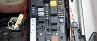
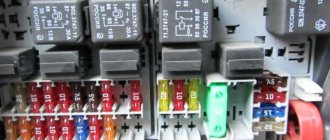
Fuses under the hood of Scenic 2
The second largest number of elements is installed in the engine compartment. There are inserts responsible for protecting the engine electronics, as well as headlights and other important devices.
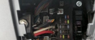
Since 2004, it has been placed in a specially designated area next to the battery. To get to it you will have to remove the cover of the generator, and then the unit itself. The features of its location are clearly visible in the photo.
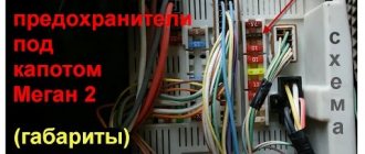
Characteristics and location
- gray – 2 and 3 A
- light brown – 5 A;
- brown - 7.5 A;
- red – 10 A;
- light blue – 15 and 30 A;
- yellow – 20 A;
- white – 25 and 30 A;
- light beige, dark green – 30 A;
- orange - 40 A, etc.
Such visual markings help to navigate when replacing elements. These parts have different functionality and sizes. It is important to further study the diagrams of their location on a specific block, pay attention to the configuration and year of manufacture of a particular Renault model. The correct selection of parts is the topic of a separate review.
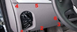
There are several similar node blocks in the car. In addition to fuses, there are various relays. These devices are located like this:
- to the left of the steering wheel under the hatch cover;
- under the driver's seat;
- under the battery (protective switching unit);
- under the protective switching unit (power circuit protection);
- on the positive terminal of the battery.
Car owners of Renault cars most often have to deal with the first and third devices. Let's look at how to get to everything.
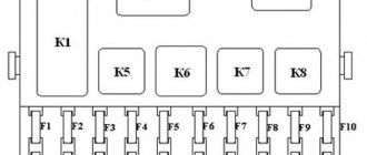
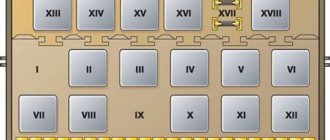
Scenic 2 fuse diagram
Below are options that are suitable for standard and Grand, gasoline engines and diesel engines. The scheme corresponds to that for the parallel generation of Megane and Coupe conso, produced in the same period between 2004 and 2008. The main unit is similar to the one installed on the 2000 car. Only an additional location has been added under the passenger seat.
The explanation of each scheme is presented in the form of a table. Inside the car
| Circuit breakers | Power, A | What protects |
| C | 40 A | Interior fan |
| D | 40 A | Rear door impulse windows or power window relay (left-hand drive vehicles) |
| E | 20 A | Electric sunroof |
| F | 10 A | ABS control unit and trajectory stabilization systems |
| G | 15 A | Audio system; headlight washer relay; cigarette lighter in front; heated seats; windshield washers; diesel fuel heater relay; climate control; Climate control unit; rear view mirror with electrochromic coating; security alarm; central communication unit |
| H | 15 A | Stop signal |
| I | 5 A | Xenon lamp ECU power supply relay; power supply unit for the actuator of xenon lamps; glove box light |
| J | 25 A | Driver's door power window |
| K | 25 A | Passenger's door window regulator; power window relay (right-hand drive vehicles) |
| L | 20 A | Audio system; electrically adjustable exterior rear view mirrors; signaling; tidy; center console |
| M | 15 A | Sound signal; diagnostic connector; headlight washer relay |
| N | 15 A | Rear window wiper motor |
| O | 20 A | UCH; Air conditioning control unit; brake light relay (B) |
| T | 20 A | scenic 2 cigarette lighter. |
| S | 3 A | Electric fan and interior temperature sensor; rearview mirror; rain and light sensors |
| U | 20 A | Central locking or internal door handle locking system |
| V | — | Spare |
| W | 7.5 A | Heated exterior mirrors |
Relay:
- Electric windows or xenon lamps
- Brake light relay
Additional unit in the cabin
| Circuit breakers | Power, A | What protects |
| 1 | 25 A | Automatic parking brake |
| 2 | 20 A | Heated driver and passenger seats |
| 3 | 10 A | Spare |
| 4 | 10 A | Power socket for equipment on the console, electric locking drive and glove box illumination lamp |
| 5 | 10 A | Power outlet 2 rows of seats |
| 6 | 10 A | Main cigarette lighter |
| 7 | 50 A | Consumer appliance relay, second power relay for the above fuses 2, 4, 5 and 6 |
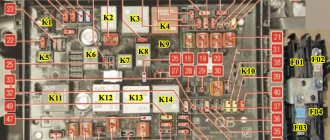
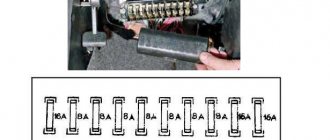
Mounting block under the hood
| Circuit breakers | Power, A | What protects |
| 3 | 25 A | Starter traction relay |
| 4 | 10 A | Air conditioning compressor clutch |
| 5A | 15 A | Electric steering column lock |
| 5C | 10 A | Reversing light |
| 5D | 5 A | Injection computer and electric steering column lock (“+” after the ignition switch) |
| 5E | 5 A | Airbag computer and electric power steering (“+” after ignition switch) |
| 5F | 7.5 A | “+” after the ignition switch (in the cabin): selector lever position indicator; speed controller and limiter; additional interior heater relay; diagnostic connector; rearview mirror; rain sensor and solar radiation intensity (depending on modification); Security alarm control unit; Parking control ECU; audio system |
| 5H | 5 A | Automatic transmission (“+” after ignition switch) |
| 5G | 10 A | Not used (or “+” after the ignition switch to the liquefied gas supply system, if equipped) |
| 6 | 30 A | Rear window heating element |
| 7A | 7.5 A | Right dimensions; parking control switch; trajectory stabilization system switch; lever position indicator from the selector; Parking brake control lever |
| B7 | 7.5 A | Dimensions on the left; cigarette lighter; central locking and alarm switches; headlight range control switch; climate control panel; audio system; remote display; central communication unit; CD changer; driver's door power window switch; power exterior mirror switch; Passenger door power window lock switch; rear door power window switch; Navigation ECU; heating elements for driver and passenger seats |
| 8A | 10 A | High beam right |
| B8 | 10 A | Far left |
| 8C | 10 A | Middle right ; headlights corrector; right headlight corrector; Xenon lamp ECU |
| 8D | 10 A | Near left; left headlight corrector |
| 9 | 25 A | Windshield wiper motor |
| 10 | 20 A | Fog lights |
| 11 | 40 A | Engine cooling fan at low speed |
| 13 | 25 A | ABS control unit and trajectory stabilization systems |
| 15 | 20 A | + battery for automatic transmission (or liquefied gas power system, if available) |
| 16 | 10 A | Spare |
Main relay
It is located next to the ignition switch inside the car.
Parking brake fuse
The fusible element for protecting the electric handbrake is located in the additional interior mounting block number 1 with a power of 25 A. An additional fuse for the parking brake control handle is installed - it takes place 7A in the engine compartment with a power of 7.5 Amperes.
Air conditioner relay and fuse
The compressor clutch protection takes place 4 in the mounting block of the Scenic 2 engine compartment and is rated at 10 Amps. Its switch can be found on the compressor itself.
Starter fuse and relay
The retractor should be looked at next to this device, but its fuse No. 3 is in the engine compartment. Its power is 25 A.
Cigarette lighter fuse: where is it located?
The main element of Scenic 2 is located in the block behind the dashboard hatch cover and is indicated in the diagram by the letter T, rated at 20 Amperes. The cigarette lighter in the armrest is controlled by fuse element G, with a rating less than 5 A.
Dimension fuse
There are two of them, each responsible for its own side of the headlights, and they are located in a block under the hood. If the left side does not light up, then problems arose with fuse element B7, and if the right side, then with 7A. The power of both is 7.5 Amperes and they are simultaneously responsible for a number of other devices.
Fuel pump fuse and relay
The fuel pump element for Scenic 2 Grand px4 is located directly on the device itself.
Reverse
The fusible element is located in the engine compartment block under number 5C and has a power of 10 A.
Wiper relay
No. 7 in the additional block of the car interior.
Dashboard
The protection element for the Scenic 2 shield can be found in the cabin unit; in the diagram it is indicated by the letter L. It is designed for 20 Amperes.
Fog lights
The PTF fuse is located in the main compartment, indicated by the number 10 on the block diagram. Its power is 20 A.
Charging fuse
The plus on the battery is protected by element 15 in the motor block, rated at 20 Amperes.
Stove
Power 7.5 A, located in the engine compartment - 5F. The relay itself is next to the heater.
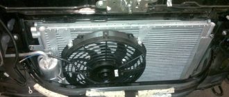
Cooling Fan
It can be found in the main block, in the diagram it is indicated by the number 11. The power of the element is 40 Amperes.
Low beam
Two adjacent elements are responsible for it - 8C and 8D with the same power of 10 Amperes.
ABS
Two elements are responsible for protection, one of which is located in the cabin, and the second in the engine compartment. The first in the diagrams is designated by the letter F, and the second by the number 13. Their power is 10 and 25 Amperes.
Wiper
The relay must be installed additionally.
Relay regulator
Located on the battery.
Scenic 2: glow plug relay
For K9K it is indicated in the diagrams by the letter G and is located in the cabin.
Window lifters
The fusible protective element of Scenic 2 is located in the engine compartment and has the number B7. Its power is 7.5 Amps.
Turns relay
Requires independent installation in a spare place.
Radio tape recorder
Indicated on the diagram of the interior mounting block by the letter G. Designed for a power of 15 Amperes.
Mirrors
Several fuses are responsible for protection, depending on the presence or absence of an electric drive, as well as the electrochromic coating. If the drive is present, then the responsibility lies with the fuse element L of the block in the car interior. If the mirror has an electrochromic coating, then - G. In the first case, the power is 15 A, and in the second - 20 A.
Interior transformation
According to drivers, Renault Scenic 2 has better sound insulation than its predecessor. But this is not enough. That is why such a topic is relevant on social networks. There are enough step-by-step manuals with photos. Insulation material is available in hardware departments, tools can be found in the garage. When complete sound insulation is done, take into account:
- work takes a long time (almost the entire vacation or several months);
- sectional installation (doors, floor, ceiling, hood, trunk).
Another popular solution is LED lighting in the interior and trunk. Materials: LED strip and wires. The length of the tape is selected according to the plan. First, suitable diode sections are cut and soldered. Then, using double-sided tape, everything is secured in the cabin or trunk. Such a system is connected to different sources (interior lighting, power supply to a light bulb in the trunk, etc.). The choice depends on the required LED backlight mode.
Replacing fuses Scenic 2
It does not require any special knowledge; the car owner will need two screwdrivers - one of which is slotted. Need to:
- remove the end cover of the instrument panel or the battery;
- Unscrew the block holder screws with a regular screwdriver;
- disconnect the electrical wires;
- use a slotted screwdriver to pry off the board with fusible elements;
- carefully pull it out;
- check the functionality of the fuses;
- replace non-working ones.
New fuses must be of the same rating as the ones that were installed.
Thermostat
There is no need to dwell separately on replacing the fuse, since the fuse element is located in the fuse block. For convenience, on the back of the protective cover there are all the symbols indicating where each fuse is located.
The procedure for replacing a thermostat is much more serious. As mentioned earlier, it may not allow antifreeze to flow through the heater radiator, which will make the cabin cold, although at the same time the Renault Scenic 2 engine itself will begin to overheat. Such a breakdown is dangerous not only for the heater, but also for the entire motor and its associated components.
Heater fan repair process
To replace the thermostat, you need to follow these instructions:
- remove the negative terminal from the battery and throw it to the side;
- relieve pressure by unscrewing the cap of the expansion tank;
- drain all antifreeze from the system (an excellent reason to replace the coolant);
- to make it more convenient, remove the air filter, remove the fasteners, move the wiring and hoses;
- Next, remove the cooling system hoses from the thermostat;
- release the cover of the problematic device;
- unscrew the fasteners holding the thermostat;
- remove the casing gasket;
- take out the thermostat itself and the old o-ring.
It is better to take a new thermostat complete with a gasket, since the old seals are hardly suitable for further use.
When assembling the assembly in reverse order, keep in mind several important rules:
- be sure to change the O-ring during assembly;
- make sure that the thermostat is installed with the spring inward;
- the gasket on the casing should be replaced;
- Fill in a new portion of coolant in small portions to prevent the occurrence of an air lock.
Now try out the new thermostat and check whether everything now works and whether the behavior of your heating system has changed. If yes, you have done a quality job.