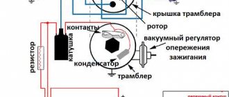
The ignition system of the VAZ 2106 car in the figure is represented by a distributor (3), a reel (6), spark plug elements (5), an ignition switch (2), wires with high voltage insulation, which are distributed to spark plug elements and a coil from the distributor and low-voltage connecting wiring .
In addition to the contact ignition system of the VAZ 2106, the “sixes” also use an ignition circuit using transistors that switch the current pulse and supply it to the spark plugs.
These include:
- Breaker-distributor. Initially, the first models until the 80s of the twentieth century were equipped with the R-125B device. It was equipped with a mechanical octane corrector, which adjusted the angular value of the ignition timing in a small range, but it was not equipped with a vacuum type regulator. After this, the ignition and fuel supply systems were modernized, as a result of which a distributor with a regulator of the vacuum operating principle and a compatible “Ozone” carburetor appeared.
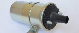
- Bobbin B117-A is a contour type, with a disconnecting magnetic circuit, filled with special oil, sealed.
- Spark plugs A17DV or their export analogues.
- Ignition switch VK347 with an anti-theft gadget, operating on the following principle: after the ignition key is moved to position III “Parking”, a metal lock pops out of the body part, which falls into a special groove in the steering shaft and does not allow it to rotate.
For emergency repairs of the ignition system of a VAZ 2106 car, it is necessary to have in stock the parts that most often fail. This is a reel and a distributor capacitor; they do not take up much space. Unfortunately, they cannot be repaired.
Malfunctions of the “six” ignition system
When operating a vehicle, the following malfunctions of the ignition system occur, which must be eliminated before further driving the vehicle.
| Malfunction | Remedy |
| The contact group has a coating of dirt, is oxidized or there are contact burn points, the distance between the contacts is increased | It is necessary to clean the contact group and adjust the gap |
| Weak fasteners or wiring caps in the low-voltage circuit have oxidized, a broken wire or a short circuit to the car body | Test the wiring and their connections, replace damaged sections of the circuit |
| Defective ignition switch (no contact closure) | Test the area, replace the defective contact element of the ignition switch |
| The capacitor is broken and does not hold capacity | Replace the product |
| There is no voltage in the primary type bobbin winding | Replace the product |
| Incorrect adjustment size in the distributor contact group | Set recommended size in contact group |
| Excessive wear of the PCB pad or increased diameter of the distributor lever bushing | Replace contact group |
| Defect in the bearing of the movable type distributor plate | Replace the bearing or the entire distributor |
| The ignition spark plug elements have an uncertain contact in the threaded part of the cylinder head, the spark plug caps from the insulated HV wires have broken or become oxidized; the insulated HV wires are dirty or their insulating layer is damaged | Test the contacts and, if necessary, restore the joints, clean or change the wiring |
| The corner of the distributor cover has undergone severe wear or has become defective and is in a non-contact state | Check the carbon of the distributor cap and, if necessary, replace it |
| Loss or loss of voltage through chips, through cracks or burnout points in the cover or rotor part of the distributor, as well as through a layer of soot or drops of moisture on the internal cavity of the distributor cover | Carry out a check, clean the cover from foreign layers of moisture and soot, replace the distributor elements (cover and rotor) if they are damaged |
| Failure of the resistance in the slider (distributor rotor) | Replace the slider resistance |
| The car bobbin has external or internal defects | Replace the car bobbin |
| The glow elements of the spark plugs (electrodes) are dirty with oil or the gap between the interacting elements is set incorrectly | Clean the spark plug elements and carry out adjustments to align the gap between the interacting elements |
| Ignition spark plug elements have external defects in the form of cracks and chips on the insulator element | It is necessary to replace spark plug elements with updated products |
| Incorrect connection of high-voltage wires to the contacts on the car distributor cover | Connect the high voltage wires according to the appropriate diagram (1-3-4-2) |
| Incorrect installation of the ignition in the vehicle | Test the installation of the MH and, if necessary, adjust it |
The table below will help you diagnose and troubleshoot problems that may arise.
The car is equipped with an engine start lock, typical for the entire line of VAZ cars, consisting of three main parts: a contact part, an anti-theft device and the lock itself.
When the anti-theft device of the lock is released, the device is replaced as a complete set. The contact part, secured in the ignition housing with a snap ring, can be replaced separately. The vehicle starting device is installed under the instrument panel on the driver's left side on the steering shaft bracket.
The flawless operation of any car depends on the trouble-free and coordinated operation of all its mechanisms. Not the last place in this series is the correct installation of the ignition system. After the car leaves the assembly line, the correct clearance is set by factory specialists. During long-term use of the car, a malfunction may occur, which may lead, as one of the reasons, to excessive fuel consumption, or as one of the main reasons, the car will stop starting. In this case, it will be necessary to install the VAZ 2106 ignition according to the factory technical parameters. You can do this yourself, having done all the necessary work yourself, or contact a professional who is familiar with all the nuances of correctly installing the ignition system.
How to remove the lock
- Be sure to remove the negative terminal from the battery. Some car enthusiasts do not do this, explaining this by low circuit voltage. However, if the wires short out during repair work, this will lead to malfunction of some electrical equipment elements.
- Turn the key to the zero position. This will make it easier to dismantle the device due to the fact that the steering wheel holding shaft will fit slightly into the secret part.
- Remove the steering column cover. To do this, unscrew the five screws connecting the top and bottom of the casing. Pull the upper part of the casing up, acting very carefully. We remove and put away all the elements of the casing.
- Having removed the casing, unscrew the screws that secure the lock itself. There are two of these screws, they are located below the switch.
- Disconnect the wires from the lock.
- In order not to break the latch during dismantling, we find a small gap on the left side of the bracket. We insert an awl or a thin nail into it and press the latch.
- Use a slotted screwdriver to remove the mechanism from the bracket.
If the latch cannot be fully pressed, you need to simultaneously slightly turn the key left and right, without turning it all the way. This will allow you to find a position in which the latch will be squeezed out completely and the lock will easily come out. Please note that anti-theft may also interfere. It moves with the key. If you turn the key to the starter position, it will take the most convenient position for removing the lock.
Another important tip: mark how the wires were connected. This will help you avoid any confusion when installing a new device.
Electronic ignition VAZ 2106
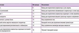
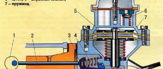
Ignition system. 1. Insulator; 2. Ignition coil housing; 3. Insulating paper windings; 4. Primary winding; 5. Secondary winding; 6. Primary winding insulating tube; 7. Output terminal for the end of the primary winding; 8. Contact screw; 9. High voltage terminal; 10. Cover; 11. Terminal “+E” for the output of the beginning of the primary and end of the secondary windings; 12. Central terminal spring; 13. Secondary winding frame; 14. External insulation of the primary winding; 15. Fastening bracket; 16. External magnetic circuit; 17. Core; 18. Contact nut; 19. Spark plug insulator; 20. Rod; 21. Spark plug body; 22. O-ring; 23. Heat sink washer; 24. Central electrode; 25. Side electrode of the spark plug; 26. Distributor roller; 27. Roller oil deflector clutch; 28. Washer; 29. Wire for power supply and distributor; 30. Cover locking spring; 31. Vacuum regulator housing; 32. Diaphragm; 33. Vacuum regulator cover; 34. Nut; 35. Vacuum regulator spring; 36. Vacuum regulator rod; 37. Cam lubrication wick; 38. Ignition timing regulator support plate; 39. Distributor rotor; 40. Side electrode with terminal; 41. Distributor cover; 42. Central electrode with terminal; 43. Angle of the central electrode; 44. Central rotor contact; 45. 5-6 kohm resistor to suppress radio interference; 46. External rotor contact; 47. Ignition timing regulator spring; 48. Centrifugal regulator plate; 49. Weight of ignition timing regulator; 50. Insulating sleeve; 51. Breaker cam; 52. Lever insulating block; 53. Breaker lever; 54. Stand with breaker contacts; 55. Breaker contacts; 56. Movable breaker plate; 57. Capacitor 0.20-0.25 µF; 58. Engine start distributor housing; 59. Bearing of the movable plate of the breaker; 60. Oiler body; 61. Terminal clamp screw; 62. Bearing lock plate; 63. Distributor; 64. Candles; 65. Ignition switch; 66. Ignition coil; 67. Generator; 68. Battery; 69. Sensor-distributor; 70. Switch; 71. Ignition timing; 72. To power supplies; 73. I. Ignition coil; 74. II.Spark plug; 75. III. Ignition distributor; 76. IV. Scheme of the classical system; 77. V. Scheme of operation of the centrifugal ignition timing regulator; 78. VI. Diagram of a contactless system.
Ignition installation for VAZ-2106
Before installing the ignition system, it is necessary to check the gap of the breaker contacts, which should be within 0.35 ± 0.05 mm. If the gap does not correspond to these parameters, then it will be necessary to install it using a twelve-sided wrench measuring 39 mm. A control lamp helps to set the ignition correctly on the VAZ 2106.
If there is no test lamp available, then you can install it on a spark by connecting a spare spark plug, which will help prevent system failure during work. The ignition is considered to be correctly set when the spark in cylinder I or IV jumps between the first and second exhaust marks. It is worth adding that in the event of oxidation of the breaker contacts, the control lamp will light constantly, regardless of the position of the distributor body.
The most common cases of malfunction of the VAZ 2106 electronic engine start include: failure of the 900706U ball bearing in the distributors, especially the latest years of production, which are equipped with a vacuum corrector diaphragm, breakdown of the distributor cap, slider and resistor in the slider.
The destruction of the ball bearing leads to uneven operation of the car engine at idle and it stops working at full power, while the tachometer needle can “walk” across its entire scale, regardless of engine speed. This situation can be corrected by performing a few simple steps:
- disconnect the vacuum hose from the distributor;
- Having tied a strong knot at its end, put it away so that it does not dangle;
- use a bar to press the vacuum corrector rod in accordance with Figure 24a; if the bar does not fit between the bend of the rod and the body, then its end is made slightly narrower, as shown in Figure 27b;
- re-adjust the gap in the breaker contacts, as described above;
- set the ignition angle to +7°30'
Now you can drive as with the ignition distributor of the first editions, but it is worth considering that in this case there will be an increase in fuel consumption by approximately a third and an increase in exhaust toxicity.
In many ways, the correct operation of the engine starting system depends on the spark plugs installed on it. With just a visual inspection of the spark plugs, you can determine the malfunction of the piston group, ignition and power systems. A spark plug with an oily working surface cannot be restored.
You can try to restore the spark plug by installing it on the second or third cylinders of a well-heated engine, or sandblast the working part. It is recommended to replace spark plugs after every 30,000 km. mileage
02/23/2013Found a mistake? Select the text with the mouse and press Ctrl+Enter Was this information helpful?
The VAZ-2106 car was produced from 1976 to 2008. This guide provides color-coded wiring diagrams (for the injector and carburetor) with a description of all elements for various modifications. The information is intended for self-repair of the six. Electrical circuits are divided into several blocks for ease of viewing via a computer or phone; there are also circuits in the form of a single picture with a description of each element - for printing on a printer. All electrical equipment of a car can be divided into the following components:
- engine starting system;
- battery charge elements;
- fuel mixture ignition system;
- elements of external and interior lighting;
- sensor system on the instrument panel;
- sound notification elements;
- fuse block.
VAZ 2107: classic type ignition adjustment
There are still quite a few 7s with the classic system installed on the roads. As practice shows, it is the most capricious and demanding, which is why we will consider it first. To adjust the angle of the closed state of the distributor, you need to remove the cover from the distributor and install the crankshaft in the position at which the gap in the contact group will be greatest. In this state, you need to loosen two bolts and place a feeler gauge with a thickness of 0.44 mm between the contacts. This is exactly what the correct gap should be. Then tighten the bolts and replace the cover.
And then the advance is adjusted. If you don’t care much about the condition of your car, then this adjustment can be done by ear. But setting the ignition timing of the VAZ 2107 will be most accurate if you use a strobe light, for example. Before tuning, be sure to remove the tube from the vacuum-type ignition corrector and plug the hole. Next, warm up the engine to operating temperature and turn it off, loosen the distributor fasteners. Connect the strobe to the battery, the wire with the sensor to the first spark plug. Please note that the sensor is non-contact, so you can simply place it on the high voltage wire.
This is exactly how the contactless ignition of the VAZ 2107 and early models is installed. Install the strobe so that its beam hits the crankshaft pulley. In this case, the beam should be parallel to the mark located on the timing cover. It is necessary to ensure by rotating the distributor body that the beam passes clearly at the moment it passes the mark on the crankshaft pulley. This, perhaps, is the whole scheme for making adjustments. All that remains is to check all the settings in motion and enjoy a comfortable ride.
VAZ2107 fuse and relay diagram
The electrical wiring of the machine is protected by fuses, which are mainly installed in the central and additional units, located at the bottom of the instrument panel on the left side next to the steering column. The circuit from the battery to the terminals and connections is closed when the car ignition is turned on.
Owners of 2106 should be aware that the old design of fuses has long become obsolete, since each time they operate they overheat, which affects the density of the cells. Lack of tight contact between the fuse and the connectors leads to their burning. Therefore, replacement of the fuse blocks is necessary. To avoid unnecessary problems with the electrical wiring, you should inspect the safety devices every six months. If the contact part burns, it is necessary to replace the fuses and clean the sockets. Today, many VAZ 2106 owners are modernizing classic blocks, replacing them with modern blade fuses.
Modifications of the VAZ-2106 car
VAZ-21060 . Modification with the symbol VAZ-21060, Izhevsk assembly of recent years of production with a VAZ-21067 injection engine with a catalyst that meets the Euro-2 environmental standard
VAZ-21061 . Modification with a VAZ-2103 engine, some cars with a similar index were equipped with a simplified engine cooling system and did not have an electric fan. Instead, an impeller was installed on the end of the coolant pump shaft. Already Russian cars were equipped with bumpers from the VAZ-2105, some examples were equipped with cleaners and headlight washers.
VAZ-21062 . Export, right-handed modification of the base six.
VAZ-21063 . A car with an improved VAZ-21011 engine, with an oil pressure sensor and an electric engine cooling fan. The release of this modification was completed in 1994.
VAZ-21064 . Export, right-handed modification, like the VAZ-21062, but the VAZ-21061 modification was taken as the basis
VAZ-21065 . A modification of the car with improved equipment, which was produced from 1990 to 2001. An engine with a volume of 1569 cm3 was installed as a power unit. Other differences from the base model include a more powerful generator, a 5-speed gearbox, a rear axle gearbox with a gear ratio of 3.9, a contactless ignition system, and a Solex carburetor. There were other changes both in the exterior and in the interior, in general it was a “luxury” version of the VAZ-2106 sedan.
VAZ-21065-01. The same VAZ-21065 but with a VAZ-2103 engine
VAZ-21066 . Export, right-hand drive modification of the VAZ-21063 car.
VAZ-21068 . A car that was produced as a carrier of units during the development period of the new VAZ-2108 and VAZ-21083 engines.
VAZ-21069 . Modification of the VAZ-2106 manufactured by order of the special services. It was equipped with a two-section rotary piston engine VAZ-411 with a power of 120 hp, VAZ-413 with a power of 140 hp.
Contact ignition system VAZ 2107
The classic contact system used on the VAZ consists of 6 components:
- Ignition switch.
- Breaker-distributor.
- Spark plug.
- Low voltage wires.
- Ignition coil.
- High voltage wires.
The ignition switch combines two parts: a lock with an anti-theft device and a contact part. The switch is secured with two screws to the left of the steering column.
The ignition coil is a step-up transformer that converts low voltage current into the high voltage needed to produce a spark in the spark plugs. The primary and secondary windings of the coil are placed in a housing and filled with transformer oil, which ensures their cooling during operation.
The ignition distributor is the most complex element of the system, consisting of many parts. The function of the distributor is to convert constant low voltage into high pulsed voltage with the distribution of pulses across the spark plugs. The design of the distributor includes a chopper, centrifugal and vacuum ignition timing regulators, a movable plate, a cover, a housing and other parts.
Design and principle of operation of a typical ignition system
On the technical side, the ignition system is part of the engine electrical equipment complex. Structurally, it consists of the following elements:
- Battery or other power source. It supplies a low voltage of 12 volts to the network.
- Switch. When you turn the key, the switch closes and low voltage flows into the energy storage device.
- Energy storage. There are two types: inductive (a transformer-type ignition coil that converts low voltage into high voltage up to 30 thousand volts) and capacitive (capacitor).
- Energy storage and distribution control unit. Depending on the type of ignition system, this may be a chopper, a transistor switch, or an ECU (electronic control unit).
- Distributor. This unit can be mechanical or electronic. It supplies certain candles with energy at a given point in time.
- High voltage circuit wires. They supply high voltage to the electrodes of the spark plugs.
- Spark plug.
The operation of the ignition system is based on the following principle: when low-voltage voltage is supplied to the network, energy is accumulated and converted, which is then distributed among the spark plugs, on the electrodes of which a spark is formed, provoking the ignition of the air-fuel mixture.
Contactless ignition system VAZ 2107
The electronic ignition circuit of the VAZ 2107 received the name “contactless” because the circuit is opened/closed not by the breaker contacts, but by an electronic switch that controls the operation of the output semiconductor transistor. The electronic (non-contact) ignition system kits for the VAZ 2107 on carburetor and injection engines are somewhat different, so there is a misconception that electronic and non-contact ignition are different systems. In reality, the operating principle of electronic ignition systems is the same.
Like a contact ignition system, electronic ignition includes spark plugs, wires, an ignition coil and a distributor. The only difference is the presence of a switch that controls the supply of high voltage to the spark plugs.
Replacing and adjusting the distributor
We can say that this is the main element, since it is with its help that an electrical impulse is distributed to the electrodes of the spark plugs, and the moment when this needs to be done is also determined. On VAZ 2107 cars, and indeed on the entire classic series, to replace the distributor you need a wrench with “13” pliers. Remove all high-voltage wires from the cover and unscrew the nut from below. Pull out the washer and remove the entire distributor. But you will be hindered by the low-voltage wire, which will need to be disconnected using a “6” key or pliers.
Installing a contactless ignition on a VAZ 2107 is not much different from the procedure for adjusting a classic one. The advance angle is the most important parameter during engine operation. The correct operation of the motor depends on how accurately it is adjusted. The more accurately the angle is set, the lower the gasoline consumption, the higher the power, torque and engine life. If we are talking about setting up a classic system, then we can distinguish several stages:
- Carrying out adjustments to the angle of the closed state of the breaker contacts.
- Setting the normal ignition timing.
Please note that on VAZ 2107 vehicles, the ignition installation is performed slightly differently if the engine is equipped with an injection system. There, the control unit is responsible for supplying an impulse to the electrodes, which analyzes the operation of the engine according to many parameters read from the sensors.
All settings can be checked only during a test drive. You need to accelerate to 50 km/h, engage 4th gear and move evenly. Then sharply press the gas pedal - detonation knocks may appear for a couple of seconds, and the engine should gradually gain speed. The contactless ignition of the VAZ 2107 is configured in the same way, the only difference from the classic one is that there is no contact-type breaker in the circuit. The advance angle is adjusted by rotating the distributor body around its axis.