To help the auto electrician, all the electrical circuits of the Russian OKA car (VAZ-1111, VAZ-11113, VAZ-11116,) are collected here. Circuit diagrams are in high resolution, so click on it to enlarge or download to your computer to view in full screen. For greater reliability and convenience, several options for electrical circuits are provided. There is also a photo of the blocks, diagram and functions of all Oka relays and fuses. At the end of the article there are some tips on repairing and maintaining the electrical part of this car.
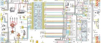
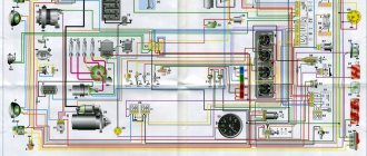
Wiring diagram VAZ-1111
1 — headlights; 2 — front direction indicators; 3 — sensor for turning on the electric fan; 4 — sound signal; 5 — electric fan of the engine cooling system; 6 — side direction indicators; 7 — spark moment sensor; 8 — spark plugs; 9 — ignition coil; 10 — electric motor of the windshield washer pump; 11 - battery; 12 — OKA generator; 13 — oil pressure warning lamp sensor; 14 — carburetor solenoid valve; 15 — coolant temperature sensor; 16 — reverse light switch; 17 - switch; 18 — plug socket for a portable lamp; 19 — brake fluid level sensor; 20 - starter; 21 — windshield wiper gearmotor; 22 — relay-interrupter for direction indicators and hazard warning lights; 23 – relay for turning on the high beam headlights; 24 — relay for turning on low beam headlights; 25 — starter activation relay; 26 — relay for turning on the electric fan; 27 — fuse block; 28 — relay-interrupter for the parking brake warning lamp; 29 — windshield wiper repeater; 30 — rear window wiper and washer switch; 31 — rear window heating switch; 32 — rear fog lamp switch; 33 — switch for the carburetor air damper warning lamp; 34 — fog light circuit fuse; 35 — control lamp for the carburetor air damper; 36 — OKA alarm switch; 37 — external lighting switch; 38 — relay for turning on the heated rear window; 39 — heater fan motor switch; 40 — brake light switch; 41 — cigarette lighter; 42 — additional resistor of the heater fan electric motor; 43 — ignition switch relay; 44 — ignition switch; 45 — three-lever switch; 46 — interior lamp; 47 — lamp switches located in the door pillars; 48 — instrument cluster; 49 — parking brake warning lamp switch; 50 — sensor for level indicator and fuel reserve; 51 — heater fan electric motor; 52 — rear lights; 53 — rear window wiper gearmotor; 54 — rear window heating element; 55 — license plate lights; 56 — rear fog lamp OKA; 57 — electric motor of the rear window washer pump; A - the order of conditional numbering of the plugs in the block of the spark torque sensor; B - the order of conditional numbering of the plugs in the gear motor blocks of the windshield and rear window wipers and the windshield wiper relay breaker; B - the order of conditional numbering of plugs in the ignition switch and three-lever switch blocks; D - the order of CONVENTIONAL numbering of plugs IN the BOXES of the instrument cluster.
Maintenance, repair
Of all the car’s electrical appliances, only power supplies require maintenance:
- Battery (periodic recharging using chargers, monitoring the level and density of the electrolyte);
- Generator (periodic check of drive tension, replacement of worn graphite brushes).
It is also important to monitor the condition of the wire insulation and prevent it from being damaged to avoid a short circuit. Oxidation of contacts often occurs at the wiring junctions, which can lead to failure of electrical appliances.
Most of the electrical network components are maintenance-free and must be replaced if they fail. Such elements include light bulbs, small electric motors, switches, relays, fuses, and sensors.
In the starter, generator, electric. In the heater and cooling system fan motors, mechanical breakdowns may occur - wear of bearings, bushings, brushes. All these components are repairable and it is often possible to restore their functionality by disassembling, troubleshooting and installing new parts to replace worn ones.
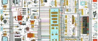
Wiring diagram VAZ-11113
The second version of the schematic diagram of the electrical equipment of the VAZ-1111, VAZ-11113 Lada-Oka car.
1 — side turn signal repeater; 2 — front direction indicator; 3 — headlight Lada Oka; 4 — electric motor of the cooling system fan; 5 — sound signal; 6 — fan motor activation sensor; 7 — electric motor for windshield washer; 8 — spark moment sensor; 9 - battery; 10 - starter; 11 - switch; 12 — spark plugs; 13 — ignition coil; 14 - generator; 15 — coolant temperature indicator sensor; 16 — sensor of the warning lamp for insufficient oil pressure; 17 — socket for a portable lamp; 18 — windshield wiper relay; 19 — brake fluid level sensor; 20 — brake signal switch; 21 — electric motor for windshield wiper; 22 — carburetor solenoid valve; 23 — reverse light switch; 24 — starter activation relay; 25 — relay for low beam headlights; 26 — relay for turning on the high beam headlights; 27 — relay-breaker for alarm and direction indicators; 28 — cigarette lighter Lada Oka; 29 — heater fan switch; 30 — additional resistor of the heater electric motor; 31 — external lighting switch; 32 — fuse block; 33 — fog lamp circuit fuse; 34 — relay for turning on the heated rear window; 35 — relay for switching on the electric motor of the cooling system fan; 36 — relay-interrupter for the warning lamp for turning on the parking brake; 37 — rear window wiper and washer switch; 38 — rear window heating switch; 39 — rear fog lamp switch; 40 — control lamp for covering the carburetor air damper; 41 — alarm switch; 42 — ignition switch; 43 — ignition relay; 44 — heater fan electric motor; 45 — fuel level indicator sensor; 46 — lamp switch in the door pillar; 47 — instrument cluster; 48 — windshield wiper switch; 49 — windshield washer switch; 50 - horn switch; 51 — headlight switch; 52 — direction indicator switch; 53 — switch for the parking brake warning lamp; 54 — interior lamp; 55 — switch for the warning lamp for covering the carburetor air damper; 56 — rear door glass washer motor; 57 — rear light; 58 — rear anti-fog lamp; 59 — license plate light; 60 — rear door glass heating element; 61 — rear door glass wiper motor; A - the order of numbering of contacts in the connecting blocks.
Similar products
The Legion-Avtodata Internet portal was created for convenient purchases: auto literature, programs for car diagnostics, diagnostic instruments, elm327 adapters, auto accessories and tools for auto repair. You can buy books and equipment for diagnosing and repairing a car in our online store. It is convenient to pay for repair and operating manuals for your chosen car brands using any of the payment systems. Order delivery of a car book by mail without prepayment, by courier in Moscow, regions and to more than 200 pick-up points throughout Russia.
Wiring diagram SeAZ VAZ-11116
in high resolution (1 MB).
1/1 — High beam headlights; 1/2 — Low beam headlights; 1/4 — Side light lamp; 2 — Front direction indicator lamp; 3 — Side direction indicator lamp; 5 — Generator with built-in voltage regulator; 9 — Hall sensor; 10 - Ignition coil; 12 — Starter Lada Oka; 13 - Spark plugs; 14 — Sound signaling device; 17 - Water temperature indicator sensor; 18 - Oil pressure warning lamp sensor; 23 - Battery; 25 - Reversing lamp switch; 26 - Brake light switch; 30 — Relay-breaker of direction indicators; 31 — Relay-breaker for the handbrake warning lamp; 32 - Windshield wiper relay; 33 - Additional resistance of the heater electric motor; 35 - Windshield wiper motor; 37 - Electric heater motor; 38 — Radiator cooling fan electric motor; 39 - Electric fan relay; 42/1 — Turn indicator switch; 42/2 — Headlight switch; 42/3 — Windshield wiper and washer switch; 42/4 - Switch for sound warning device; 44 - Ignition switch; 46 — External lighting switch; 48 - Hazard switch; 49 - Heater motor switch; 52 - Instrument cluster; 63 — Speed sensor Lada Oka; 74/1 — Thermal cigarette lighter element; 74/2 — Cigarette lighter lamp; 75 — Brake fluid level sensor; 76 - Handbrake warning lamp switch; 77 — Diagnostic block; 81 — Cartridge for connecting a portable lamp; 83 - Windshield washer pump; 87 — Interior lighting switch in the front door; 89 — Interior lamp; 93 — Sensor for level indicator and fuel reserve; 98/1 — Side light lamp; 98/2 — Turn signal lamp; 98/3 — Brake light lamp; 98/4 - Reversing lamp; 99 — License plate lamp; 104 - Electric fan thermal switch; 108 — Rear fog lamp; 112 - Rear window wiper motor; 113 — Rear window washer motor; 115 — Rear window heating element; 121 — Relay for turning on the heated rear window; 125 - Additional relay; 126 - Relay for high beam headlights; 127 - Relay for low beam headlights; 129 - Starter relay; 133 — Rear window heating switch; 136 — Rear fog lamp switch; 137 - Rear window wiper switch; 138 — Rear window washer switch; 158 - Fuel injectors; 159 — OKA watch; 168 — Relay for rear fog lights; 169 - Additional brake signal; 170 - Fuel pump relay; 171 - Electric fuel pump; 172 - Idle speed regulator; 173 - Throttle position sensor; 174 - Knock sensor; 175 - Canister purge valve; 176 - Oxygen sensor; 177 - Absolute pressure sensor; 178 - Main relay; 221 - Controller.
Useful: VAZ-2108 diagram
Common electrical faults
Common problems with electrical equipment on VAZ-1111 and 1113:
- Failure of external lighting devices. A common cause of failure is burnt out lamp filament; the unit must be replaced. If the light bulb is intact, then there may be a defect in the electrical wiring, due to which a short circuit occurs and the fuse fails. The fuse link is replaced with an identical one; it is prohibited to use parts designed for a higher current. It is also unacceptable to install homemade jumpers (“bugs”), as this can cause a fire. If a repeated burnout occurs, it is necessary to check the circuit and eliminate the wiring fault.
- Wire breaks occur at points where the insulation is subject to bending or friction against moving surfaces. An example of such a point is the junction of the door and the body. Damaged areas must be replaced with products made of similar material with an identical cross-section.
- Oxidation of contact surfaces due to moisture or aggressive liquids (for example, battery electrolyte). It is necessary to clean the surfaces down to metal, restoring the transmission of electric current.
- Relay failure associated with burnt contacts or coil breakage. The unit cannot be repaired; it must be replaced with a new one. In the event of a rapid re-failure, the vehicle's electrical system must be checked at a car service center.
- Sudden battery discharge is due to an internal short or current leakage. In winter, a partially charged battery may lose capacity due to low air temperatures. You need to charge the battery and check the condition of the wiring. If necessary, the power source must be replaced.
- Pulsating operation of external lighting lamps with an unusually bright glow indicates a breakdown of the relay regulator on the generator. Repair requires removing the unit and replacing failed components.
- Insufficient battery charge (the warning light does not go out when the engine is running). The cause may be wear on the brushes or commutator, or insufficient tension on the drive belt. The generator needs to be repaired, since the battery charge is enough for 150-200 km during the daytime.
- Poor contact between the ends of the cylindrical fuses and the spring-loaded elements in the mounting block. It arises due to the design features of the unit. Many owners, tired of dealing with the defect, install homemade blocks for knife inserts. Usually a short section from the GAZ-3110 is used, designed for 13 seats. There are self-assembled units designed for fuses and relays.
Photo gallery
The process of installing a new mounting block with blade elements.
Burnt contact of the standard unit
Destruction from local heating is clearly visible
Jumpers on the new block required to reduce the number of insertion locations
Wired unit
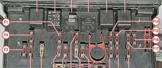
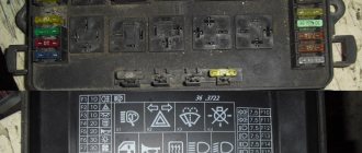
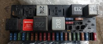
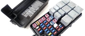
OKA relay and fuse block
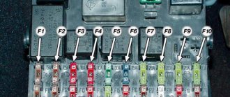
Auto fuse box
The fuse box is located inside the car under the instrument panel, on the left side of the steering column. The top is closed with a lid with a latch.
1 (16A) - Heater fan electric motor / Relay (winding) and sensor for turning on the engine cooling fan electric motor / Relay (winding) for turning on the rear window heating / Electric motors for the rear window wiper and washer and windshield washer.
2 (8A) - Carburetor solenoid valve / Relay and windshield wiper motor / Turn signals and relay-breaker for turn signals and hazard warning lights (in turn signal mode) / Turn signal warning lamp / Rear lights (reversing lamps) / Field winding generator (when starting the engine) / Carburetor choke warning light / Relay breaker and warning light for parking brake system and insufficient brake fluid level / Oil pressure warning light / Battery discharge warning light / Coolant temperature gauge / Fuel level gauge with warning light reserve.
3 (8A) - Left headlight (high beam) / High beam indicator lamp.
4 (8A) - Right headlight (high beam).
5 (8A) - Left headlight (low beam).
6 (8A) - Right headlight (low beam).
7 (8A) - Left headlight (side light) / Left rear light (side light) / License plate lights / Side light indicator lamp.
8 (8A) - Right headlight (side light) / Right rear light (side light) / Instrument cluster lighting lamp / VAZ-1111 cigarette lighter lighting lamp.
9 (16A) - Direction indicators and relay-breaker for direction indicators and hazard warning lights in hazard warning mode / Rear window heating element and relay (contacts) for its activation.
10 (16A) - Electric motor of the engine cooling system fan and relay (contacts) for turning it on / Sound signal / Socket for a portable lamp / Interior lighting / Rear lights (brake lamps) / Cigarette lighter.
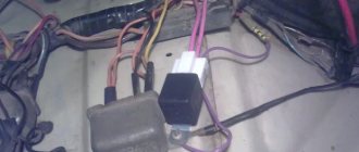
Car relay block
A block of five relays is located in the car interior under the instrument panel, on the left side of the steering column. There are also additionally placed relays.
- Engine Radiator Fan Relay
- Low beam relay
- High beam relay
- Starter relay VAZ-1111
- Heated rear window relay
The front wiper relay (RS-514 (2101-5205150)) is located under the upholstery, left side panel. The parking brake warning lamp relay (RS-492 (2101-3803150)) is located behind the instrument cluster, next to the turn signal relay. The ignition relay (90.3747-10 / 113.3747-10 / 2105-3747210-20) is secured with a self-tapping screw from inside the instrument panel. The hazard warning and direction indicator relay (494.3747 / 2105-3747010-01) is located behind the instrument cluster.
Separation by purpose
By purpose, the equipment is divided into:
- Power supplies;
- Protective means;
- Controls;
- Instrumentation;
- Actuators;
Some circuit components have dual purposes. These include relays, which are both control elements and protective devices.
Power supplies
Power sources include the battery and generator. The battery powers the electricity. devices and ensures their operation when the power unit is turned off. After starting the engine, the on-board network is powered from the generator, which also ensures that the battery is recharged.
Protective components
Protective means prevent burnout of electrical appliances and electrical circuits during short circuits. The main protective elements are fuses. For convenience, all protective elements are collected in one place - the fuse box, which in Oka is located under the front panel on the driver’s side.
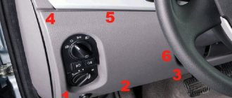
Controls
Control elements include all components responsible for turning on, switching and turning off electrical appliances. This category combines the ignition switch, all kinds of switches and switches. Most of these elements are located within direct reach of the driver - on the front panel, steering column. But there are switches that the driver acts on through certain components - brake light switches, a sensor for turning on the choke warning light, etc.
instrumentation
Control and measuring devices provide the driver with information about the operation of certain components and mechanisms, operational indicators - fuel level, coolant temperature, oil pressure, etc. Some types of these devices display accurate information, while others are presented in the form of warning lamps that are triggered only when an emergency occurs. malfunctions.
Measuring instruments combine sensors installed on the required components and mechanisms, and signal elements located on the dashboard.
Actuating devices
Actuators are components that perform one or another function - they illuminate, operate components, etc. These include electric motors, lighting lamps, a sound signal, a cigarette lighter, etc.
Basic Switch Elements
The switch circuit is quite simple, but making this unit yourself is pointless, since buying a ready-made version will be much easier. Installation must be carried out as competently as possible, otherwise the device will not operate correctly. In addition, when using transistors, you need to carefully select them according to their parameters, and for this you need to have high-quality measuring equipment. Unfortunately, for two identical semiconductors, the spread of characteristics can be very large. And this affects the operation of the device.
The switch is. Switch diagram. How to check the ignition switch
The switch is an electronic component to ensure the operation of a contactless ignition system. It is transitional between contact and microprocessor. The latter, the most advanced, allows you to control the torque using data read from sensors - oxygen, speed, engine speed and others. But there are still many cars on the roads that have both contact breakers and contactless ones. Therefore, for maintenance and diagnostics, you need to know the purpose of all elements, as well as troubleshooting methods and their main symptoms. Before testing the switch, review all parts carefully.