Preparing the car before connecting
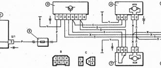
What controls the central locking? A special block to which the lock actuator wires fit. There are also two wires connected to it, connected to the driver's door microphone. More precisely, this wire is used alone in “Grant”, it has a brown sheath, and the second contact from the “micrik” is connected to ground.
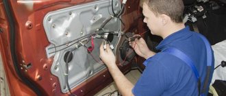
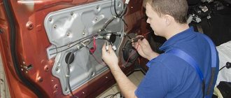
The “micric” itself is located inside the actuator. So, the first piece of advice: after removing the left front door trim, you need to find the cable going from the actuator to the 7-pin connector.
Depending on the configuration, under the trim you will see the following:
- There are 6 wires suitable for the connector (from 2 microphones and a drive);
- The cords from the electric drive (pins “2/7”) are not connected, but there is still a brown wire connected to pin “1”;
- Only those wires that, according to the diagram, should be connected to contacts “4/6” are missing.
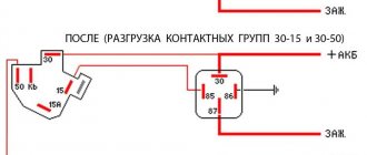
Connecting the signaling means that the wires from contacts “2/7” are still connected to the central locking control unit. The cords coming from the three actuators are always connected to the standard unit. You need to connect a fourth one, if this is not done by the factory. You may have to lay a two-wire cable from the door to the central lock control unit:
The central locking control unit is located under the fuse block, it is designated BUBD-2190.
Here's how one of the car owners coped with the task:
The cords that come out of the door are connected to the wires of the standard terminal block. The following connector pins are used: “3” and “4”. The main thing is not to confuse them. Take another look at the diagram to see what exactly we are talking about.
How to make a remote control
Speaking about connecting a central locking system from China, we will discuss the installation of a central locking remote control
A blue cable comes from the universal remote control unit for opening/locking the trunk. When a key is pressed, there is a minus sign on it. It is possible to connect the trunk using an additional four-pin relay.
By connecting the brown wire, installation and removal from the alarm involves blinking of the side lights or turn signals. Green cable – control of glass finishing. When the doors are closed, a signal is given to it for about half a minute, which is enough to raise the windows from the fully retracted position.
Pay attention to the insulation and cable connections. Do not start connecting without understanding the electrical circuit and the basic operation of the central locker. An incorrect connection diagram for a central lock from China may result in a fire.
The attractive low-price remote control with Ali is now extremely popular. Thanks to this block, the remote control is connected to a common system or the car is equipped with central locking (you need to have four two-wire activators). Of course, we are not talking about any kind of car protection from theft. This cheap central locking control unit is capable of performing only a service task. The best option to choose a central locking system is to look at reviews. For example, 18650 batteries from China, which ones are better? and much more, you can choose and see in action, as some have videos.
Connecting the signaling to the central locking system
Now we get to the most interesting part. The contacts of the signaling relay must be connected to the gap in the brown wire (see diagram in Chapter 1). Moreover, this will be required regardless of the configuration. Oddly enough, we won’t need power cables at all. And the task now looks like this: you need a two-wire signal cable connected to the break in the brown cord.
The moral here is:
- If you were able to remove the central lock control unit, connect the cable to the break in the wire connected to pin “7” of the control unit;
- If you have removed the door trim, then pull the cable out of it (from the point where the brown cord breaks).
It is clear that the second side of the cable must reach the relay connector of your alarm.
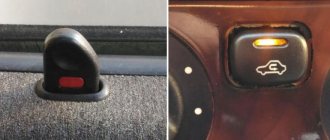
Option for the “Lux” package
So, this means that there is a button on the armrest in the cabin that allows you to lock the locks. From one of the contacts of the button, to which a “plus” is applied when pressed, you need to stretch the cord to the signaling unit. Nothing else is required, and you can connect the alarm according to the following scheme:
According to reviews, this option is suitable if we are talking specifically about the “luxury” configuration. By the way, the resistor can be connected to the gap in the wire designated “blue” (the common contacts are then connected with a jumper).
It must be remembered that when working with any electrical equipment, you must first remove the negative terminal from the battery.
Each cord that is re-laid must not touch metal surfaces. Otherwise, in places of contact, the wire is protected with a tube that can withstand temperatures of 250 degrees. This is how you can protect yourself from unforeseen consequences.
Option for the “Norma” configuration
Let's say there is no button in the cabin that allows you to perform emergency closing. Then you need to connect the signaling to the central locking system according to the following scheme:
As you can see, unlike the first option, there are no resistors here, and positive voltage is not used at all. But in the luxury configuration the effect that is characteristic of this scheme will not be observed:
- We perform closing from the key fob - all locks are locked;
- We try to open the locks with the key fob - only the driver's lock unlocks.
If you are satisfied with this property, try to implement the scheme in practice. And other options, more advanced, look much more complicated.
Read what is said about installation safety in the previous chapter. Do not neglect the advice about disconnecting the negative terminal. We work only with signal circuits, so nothing will fail even if connected incorrectly. However, be careful not to confuse the locking and unlocking relays, which are located in the alarm unit. This unit is usually equipped with a 6-pin connector (for details, see the signaling manufacturer's instructions).
GAZ 31 Volga Schrödinger › Logbook › installation of a Chinese central lock and window closer
I spent three days and about two thousand rubles, but it was worth it in my opinion!
To implement my plan, I purchased a central lock with a flip key like this
First, I chose the place where the central locking unit would be located. I decided to place it on the right under the side trim directly on the control unit, since there are so many things crammed on the left
Next, it remains to stretch the wires from the activators to the central locking and connect the positive wires from both activators with a gray wire, and the negative wires with a gray/black wire. If the lock does not work correctly, then simply swap the wires. minuses are gray, and pluses are gray/black. Next, pull the red wire to the positive. I took the positive from the fuse box under the hood. We hook the black wire to the body. The green wire goes to where the closer unit will be located. The green wire is the control minus for the closer. And blue is the control minus for opening the trunk. Let's take it to the lever to open the trunk. As a result, we were left with a yellow and yellow/black rein, as well as an orange and orange/black one. I tried for a long time to figure out what these wires were and what they were for, but I still couldn’t figure it out. As a result, I found information on the Internet that the yellow wires need to be hooked to + and the orange wires to the body. And everything worked!
After making sure that everything worked as it should, I assembled the interior and began to disassemble it again. But in a different place. I decided to place the closer block in the dashboard behind the newly installed pocket. Since it’s close to pull the wires to the power window buttons from here and it’s easy to get there if something happens. Plus I also took it from the same wire that I ran to the central locking. This is the red wire with the fuse on the closer. Black wire to the body. There are also two control wires. For the yen, this is the manager plus brown-black and the manager minus brown. Since the control minus comes with the central locking system, I connected it with the control minus of the Brown Closer. Next we need to cut the wire that goes from the button on the ESP to the window lift. Mine was brown. We attach the gray wire from the closer to one end of the cut wire, and the gray/white wire to the other. On the other button we do the same, but connect the yellow and yellow/white wires of the closer.
All. The door closer works and locks the doors and raises the windows. However, I want to be able to sometimes leave the windows ajar, so I open the plus on the closer with a button via a relay
Source
Granta and Starline - all options
Security systems with remote control provide additional protection for vehicles from burglary or theft. The correct control of the standard equipment of the car depends on the correct choice of the alarm connection point on the Lada Granta. It is also important to ensure stable power supply to the signaling head unit and protect components from unauthorized access through technological openings in the car body.
Installation
Installing an alarm system on a Lada Granta with your own hands consists of several stages:
- Removing the plastic trim of the steering column. Then the instrument cluster is removed and the card installed on the driver's door is removed. The parts are secured with screws and plastic pistons, which are removed with a special mounting spatula.
- The installation point of the head unit depends on the dimensions and characteristics of the product. Small-sized modules of Starline or Pandora products are located behind the instrument cluster.
- Connect the control diode to the front roof pillar trim on the driver's side. The antenna unit (some of the complexes contain an impact detection sensor) is glued to the upper edge of the windshield. If the owner has previously installed the unit on a different point on the glass, it is recommended to replace the layer of 2-sided adhesive tape that is applied to the module body at the factory.
- The siren horn is placed in the engine compartment, the cable is routed into the vehicle interior through standard channels made in the engine panel. Since overheating of the housing leads to damage to the electronics of the unit, the horn is protected from the exhaust manifold. The base of the siren is secured with screws that are screwed into pre-drilled holes.
- When installing an alarm with auto start, it is necessary to install a sensor that measures the temperature of the engine block. The device is secured with a nut in accordance with the manufacturer’s recommendations; it is prohibited to squeeze the element during installation.
Installation Rules
An alarm installation map (individual for each device model) is attached to the factory installation instructions. When performing installation work, secure fixation of the elements with screws or plastic clamps is ensured. When using 2-sided adhesive tape, the adhesive layer may be destroyed due to temperature changes, loose parts are damaged and can destroy the standard electrical wiring of the car.
It is not recommended to install parts of the security system next to the standard electronic controllers of the car. The location of the head unit is located at a distance from the ventilation ducts of the standard air conditioning unit. To ensure cooling, natural ventilation must be provided.
All work related to connecting electrical wiring is carried out with the vehicle de-energized.
The wires are connected by twisting; to improve the quality of contact, solder or special metal tubes are used. It is not recommended to cut cables that are not used for switching. The cords are neatly rolled into rolls and attached to the car’s structural parts with plastic clamps.
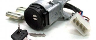
Immobilizer and its location
The immobilizer is a ring antenna located in the ignition circuit control lock. The plant equips cars with 2 keys, inside of which there is a special chip. If the microcircuit is correctly recognized, the blocking of the engine starting circuits is disabled. Automatic engine start, performed without a key, is only possible when an immobilizer bypass is installed. The device is a separate unit with a chip or a copy of the key; some alarms use an electronic unit that simulates the signal from a standard key.
Wiring connection
After the alarm components are installed on the Grant with your own hands, you should connect the nodes with standard wiring bundles. The central harness is connected to the on-board network and additional components according to the circuit recommended by the equipment manufacturer. The positive signal is supplied from the battery terminal or from the lock, the negative terminal is connected to the car body. For connection, bolts located inside the instrument panel are used.
To use autostart, you need to connect the switches located under the brake pedal and under the parking brake lever. The contact group under the pedal is designed for additional protection of the car; when you try to brake in a stolen car, the engine is turned off. Additionally, it is necessary to use the cord that controls the operation of the power unit. The signal comes from the tachometer; some of the alarms support voltage control in the on-board network.
The central harness is connected to the direction indicator control unit. Fuses should be provided in the power circuits; the rating of the products depends on the type of security system. The design of the machine does not provide end elements that fix the position of the doors. The parts are installed in separate holes, which are made on the body pillars. The connecting cables are routed under the sill trim.
Connection to central locking
The head units of the security complex are connected to the central locking system, which is used on Grant vehicles. For switching, you need to cut the wire covered with a layer of brown insulation. The switching takes place in the driver's door or near the central locking control unit. The opposite end of the cord is connected to the corresponding output of the head alarm module (the location of the contact depends on the model and manufacturer of the complex). There is no need to connect power cables to ensure operation of the nodes.
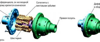
Types of central locking in a car
Based on the principle of operation of the device and connection diagram of the central lock from China, it can be divided into two types:
- Pneumatic. The activator moves due to a change in gas compression in the system. Now it is not used; previously they were installed by Audi, Volkswagen, BMW, Mercedes. It is financially unreasonable to renew this system or install it yourself. It is much easier to install electric activators by connecting everything to the remote control unit.
- Electrical. Electric activators are installed in the doors. Various mechanisms either have a personal control unit or are controlled by one unit (this scheme is used in cheap machines).
Electric ones, regardless of the method of connecting the central lock from China, are in turn divided into two types:
- with plus control (the same is installed mainly on glass closers from China);
- with negative potential control.
Source