For the first time, the option to control the central locking from a button on the instrument panel was implemented in a luxury vehicle (GLS) in March 2014, but from October 2021, the central locking control scheme was changed in accordance with the description in this section. We tell you how the standard central lock on a Chevrolet Niva works and how to install it yourself.
The central locking of this vehicle is controlled by:
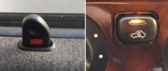
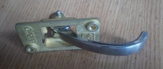
- A latch in the driver's door, which is the factory design of the central locking system on a standard Chevrolet Niva car; however, a feature of the luxury configuration is that in this version the central locking is controlled by a latch only when the ignition is turned off.
- A button on the instrument panel when the ignition is on, which is also a feature of this car.
- Key fob installed security alarm, but this option will not be considered in this section.
When the car's ignition is turned on, control of the central locking switches from the latch to a button located on the dashboard, which is used both to close all the car's locks and to open them when pressed again.
The button does not directly control the servos of the latch in the car doors - it controls the car's central locking via the standard BUDM. 30 seconds after turning off the ignition, control of the central locking returns to the driver's door latch, and all the car's locks are adjusted to the position of the latch.
In addition to the standard illumination of the button when the dimensions are turned on, it also features illumination of the central locking status based on the position of the driver's door latch: orange means that the car's locks must be closed.
Causes of central locking malfunctions
Most often, the electrical part of the solenoids control fails , and the locks themselves are considered relatively reliable.
The central locking of a Chevy Niva car works on the following principle: the signal for opening or closing the doors is transmitted by pressing a button on the key or turning the cylinder in the driver's door, while the signal passes through the central locking control unit and the on-board computer.
This scheme has its weaknesses, and the main reasons for failure are the following factors::
- short circuit in the circuit and fuse failure;
- chafing of wiring in flexible corrugation, loss of contact at joints due to vibrations and moisture ingress;
- central locking relay malfunction;
- error in the central locking control unit;
- lock motor failure.
Advice! If the car has an alarm system, the central locking may not open due to a malfunction of the alarm system. Perhaps the reason lies in the dead battery of the alarm control panel.
Operating principle and central locking diagram
Central locking has been installed on the VAZ 2123 since 2004 . Since then, the Chevy Niva central locking scheme has not changed fundamentally and is installed on cars starting with the “Norma” configuration. To control the remote door opening, a remote control (remote control with a flip key) is used. It combines the functions of an immobilizer, ignition key, and door key. The signal from the remote control is received by the electrical package control unit (1118-6512010), which is responsible for opening the doors.
Pressing a button on the remote control opens or closes all car doors , including the trunk door. In the same way, the central locking is triggered when the key in the driver's door is turned half a turn to the right or left.
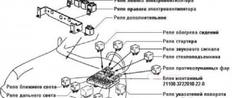
The operation of the electrical network is controlled by a standard relay type 90.3747 , a 20 A fuse, limit switches in each door, and gearmotors on the lock mechanisms.
A special feature of the Chevrolet Niva Central Locker is the ability to manually open and close the doors, even with the battery removed.
Important! The gearmotors are equipped with protection against overheating and turn off for a while after repeated activation of the central locking system.
Preparing to connect the alarm
Before directly connecting and connecting the signaling system, you should first find out how the lock itself works. After this, find the access points that are shown in the instructions on the transport. Alarms are mostly universal. They are installed on turbocharged, diesel or gasoline Niva Chevrolet engines.
Also interesting: How to bleed the brakes on a Chevrolet Niva correctly
Further actions:
- Before installation, you need to remove the protective structure from the steering wheel, remove five self-tapping screws with two screws. Then unscrew the panel screws that cover the mounting block and pull out the block.
- Remove the instrument panel trim and remove all screws. Unfasten the dashboard.
- Place a siren with a temperature sensor and a hood limit switch in the car engine compartment.
- Connect the antenna unit in the upper corner of the windshield. Place the LED type indicator on the left pillar.
- Attach the shock sensor to the steering wheel bracket, and place the service button in a hidden but easy to access place.
Ways to solve problems with central locking Niva Chevrolet
Before starting work, it is recommended to evaluate your repair skills and experience with electrical wiring in a car. Special equipment may be required, and at a minimum, a tester is required to diagnose electrical circuits. Troubleshooting always starts from simple to complex.
Fuse failure
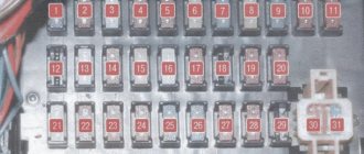
The fuse is the first thing every car enthusiast should check if the central locking stops working . The symptom will be the failure of all doors to close with the button at the same time. It's easy to check - just open the mounting block and replace it with a serviceable one of the same rating.
Most often, the cause of its burnout is a short circuit or overload in the circuit . In the mounting block of cars manufactured before 2009, it is designated F6; on cars after 2010, it is located under the number F10.
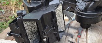
Gearmotors
Their breakdown does not occur often, but repairing or replacing motors in doors requires partial disassembly of the door and removal of the upholstery . A faulty motor can be detected by the silence on its part when the central locking system is activated or incorrect operation (does not open completely, fires every other time, extraneous sounds).
Functionality is checked with a multimeter or by connecting to the battery directly. Replace the gearmotors with a new assembly if the old one cannot be repaired.
Advice! It happens that the sounds of the motor operating are heard, but the door does not respond to signals from the key. In this case, it is necessary to check the rods coming from the locks to the gearmotors and door handles.
Wiring
This is probably the weakest point in the entire electrical circuit of the central locking system . The problem is that the door is a moving element, so the wiring harnesses are constantly being twisted in these places.
In addition to the central locking system, alarm wires, limit switches, audio systems, and power windows enter the door. Despite the rational S-shaped bend of the door wiring in the corrugation, damage to one or more wires occurs. The second weak point is the contacts inside the door.
The integrity of the wiring is checked by “ringing” suspicious sections of the circuit . The found break is cleaned and connected by soldering or crimping bushings. Replacing a broken wire entirely with a new one is not always advisable due to the complexity of the work.
Relay circuit
Power to the central locking can be supplied through the main relay used for low beam headlights and interior lighting. There are also schemes with a separate relay for the central locking, which is installed next to the control unit of the door opening system.
Typical 4-pin relays rarely fail, but if they do, the problem is easy to diagnose . To do this, replace the relay with any working one from the mounting block. If after this the central locking works, the cause of the breakdown has been found. An alternative option is to check the relay with a tester.
Central locking control unit
This block is present only on cars with the “Norma” configuration and higher . A common reason for its failure is a short circuit in the circuit or large voltage surges, leading to melting of the microcircuit contacts. Diagnosed visually (traces of melting on the body) or with an electrical tester.
The central locking unit, as a rule, is not repaired and is simply replaced with a new one.
On-board computer (ECU)
On Chevy Niva, the central locking scheme on later cars involves the participation of the on-board computer in the processes of opening and closing doors, as well as setting the alarm. Such a scheme allows you to expand the functionality of the central locking system, connect an alarm system with auto start and make the operation of the car more comfortable.
Information about errors and malfunctions of the central locking is obtained through a scanner or PC , which is connected to the car via a standard OBD2 connector. Errors in the computer are one of the reasons why remote opening does not work. In the application you can reset errors and find out the cause of the problem. In difficult cases, the control unit is reflashed.
Installing a car alarm on a Chevrolet Niva - Connection points, location and colors of wires
The versatility of the Tomahawk anti-theft system allows it to be installed on Chevrolet Niva cars.
How to install a Tomahawk alarm on a Chevrolet Niva yourself? It is not difficult to install the device; it is enough to have a small set of tools, instructions, and strict adherence to the diagram. Unscrew the four screws securing the instrument panel. Remove the decorative protection under the dashboard. Then we connect the door open alarm wire to the trunk end switch. Open the hood and install the engine temperature sensor on the engine itself.
Renault Logan installation of Alarm StarLine B9 installation map. Install an Alarm Car alarm in Riga - installation,
Signals from the door and trunk switches are located on the wires in pins 30 and 40 of the green insert of the black BCM connector. Wires must be laid in dry places. Following the instructions for a specific alarm system, any owner can install security on a Renault Logan.
The wires are located in the black insert of the white BCM connector. They are located on the door, in the passenger compartment and in the trunk. Unscrew the four screws securing the instrument panel. Remove the decorative protection under the dashboard.
We remove the decorative protection under the torpedo - on the left there is a clip. We remove the decorative protection under the torpedo - on the right there is a clip. We remove the decorative protection under the torpedo - there are 3 clips in the center. We unscrew the screw and remove the BCM unit. Work under the hood. Attaching the siren to the screw and M6 nut. General view of the siren. Install the hood end cap, cut off 3 division.
The hood switch is installed. We lay the wire under the hood through the standard rubber band on the driver's side.
Almost every owner of his car has thought about how to equip his iron horse with protection against theft. This also applies to owners of the Lada Granta, because the standard and standard configurations are not equipped from the factory with any anti-theft system other than an immobilizer. And in this article we will tell you how to install an alarm system on a car with your own hands, because in essence, despite the wide variety of different types and companies, the procedure for installing them is quite similar.
Every modern car must be equipped with a reliable anti-theft system that will prevent break-ins and theft of the vehicle. Since standard anti-theft installations are not particularly reliable, car owners have to install alarms on their cars themselves. What are the alarm connection points in a Niva Chevrolet car, and how to connect the alarm correctly - find out from this material.
Control module location
Depending on the configuration, the Niva's electrical circuit can be supplemented with a standard alarm system, which, in essence, is a central locking system. If there is a lock, the system is controlled using one module - a block, which represents the signaling system.
The standard anti-theft system is characterized by the following monitoring features:
- it monitors the condition of the internal perimeter of the vehicle body using ultrasound;
- in the same way, the system monitors the safety of the car interior;
- The standard anti-theft installation also protects the hood and luggage compartment of the car from break-ins.
Since this system is standard, it does not have a notification function. That is, unlike a traditional signaling system, a standard anti-theft installation is not equipped with a siren. In other words, its main function is to lock the car doors, but if someone tries to break into the car or steal it, the driver will not know about it.
It is better to connect power cables by twisting, but knowing how to do it correctly is an art.
Many car enthusiasts are faced with a situation where they need to connect an alarm system to a Chevrolet Niva. Although this is a labor-intensive process, it can be done on your own. From the article you will learn how to prepare the system, install an alarm system on a Chevrolet Niva with your own hands and test it in action.
Driver's door - white/bluePassenger's door - yellow/blackrear doors - white/blacktrunk - white/redhood - green/blackAll limit switches are negative
Turns - blue and blue/black
The central locking block is behind the mounting block. Central locking (-) - closing - 7th leg, opening - 2nd leg. To control the central lock, you need to solder to the central locking block.
On this car, the first press of the standard key fob opens the driver's door, the second press opens the passenger door. One of the well-known sites has connection points using an additional relay. But I don’t think this method is the best. That's why I offer mine. The central locking unit on the Chevy Niva is from Kalina.
We remove the instrument panel of Mitsubishi Pajero 4.
To do this, remove the front cover, unscrew the 3 screws securing the shield and remove it 4. We install a siren, an engine temperature sensor and a hood switch under the hood of the Mitsubishi Pajero 4.
We route the wires through the standard seal on the right side of the engine shield 5.
We install an antenna with a built-in shock sensor and mitsubishi pajero alarm connection points on the Mitsubishi Pajero windshield, an LED in the left pillar of the windshield, a service button in any convenient place 6.
Author Alexander
Author Alexander
Many car enthusiasts are faced with a situation where they need to connect an alarm system to a Chevrolet Niva. Although this is a labor-intensive process, it can be done on your own. From the article you will learn how to prepare the system, install an alarm system on a Chevrolet Niva with your own hands and test it in action.
Central locking does not work on Niva Chevrolet
The failure of the car's central locking is more associated with a malfunction in the electrical part than in the mechanics. So, most motorists go to auto electricians to fix the problem, because they do not imagine the reasons why this problem may appear.
Factors
So, let's consider what factors influence the malfunction of the central locking unit:
- Fuse.
- Drive motors.
- Wiring.
- Relay.
- Central locking control unit.
- On-board computer.
Methods for solving the problem
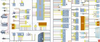
Central locking connection diagram.
When all the causes are identified, you can begin to eliminate the problems. It is worth noting that the electrical part is quite complex, and therefore it is necessary to have some knowledge and skills to troubleshoot the problem. If a car enthusiast has no idea about the design features of auto electrics, then it is recommended to contact a professional car service center to fix the problem.
Before you begin to solve the problem, you need to understand the structure of the central locking system.
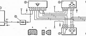
Central locking connection diagram
Diagram of the door lock system: 1 – mounting block; 2 – control unit; 3 – gear motor for locking the passenger door lock; 4 – rear door locking motor; 5 – driver’s door locking motor; A – to power supplies; B – scheme of conditional numbering of plugs in the control unit block; C – scheme for the conditional numbering of plugs in the blocks of geared motors for locking locks
Fuse failure
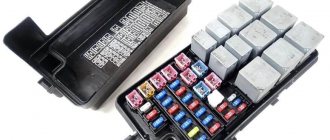
The problem should be looked for in the fuse box, namely in a blown fuse.
The first place where all malfunctions occur in the electrical part of the car is the mounting block. A blown fuse may cause the central locking to stop working. Simply replacing this element can fix the problem. Of course, if you examine the fuse, and it is intact and not damaged, then you should look for a breakdown in another place.
Drive motors
Drive motor malfunction.
There are cases when drive motors in car doors burn out. This malfunction is quite rare, but it should not be excluded.
To troubleshoot the problem, you will have to disassemble each door step by step and remove each motor for diagnostics. You can determine the operability of the elements using a conventional multimeter, or in its absence, connect the drive to the battery. If after checking it turns out that the motors are working, then you should look for the reason elsewhere.
Wiring
Malfunction caused by a wiring problem.
Repeatedly, the problem with the central locking being inoperable was the wiring.
So, a short circuit or broken wire does not conduct a signal to the central locking control unit. To determine the lack of contact, you need to ring each wire with a multimeter. If it is discovered that there is a break in the circuit, then it is worth replacing the broken element with a new one. But, as practice shows, most motorists simply cut the wiring at the point where contact is lost, strip and insulate the wires.
The relay has fallen off - one of the signs of a malfunction of the central locking.
Another reason for a non-functioning central lock could be a failure of the relay in the mounting block . So, you need to take out the element and carry out diagnostics using a tester. If diagnostic operations show that the relay is “dead,” it must be replaced with a new one.
Central locking control unit
The central locking control unit shows signs of failure of some of its spare parts.
A short circuit in the on-board system not only burns out the wiring and fuse, but can also cause a malfunction of the central locking control unit. So, to diagnose this control element, it must be removed from the door. Then, using a tester, ring the contact connections. Often, if the central locking control unit fails, it is replaced, but there are “kulibins” that resolder the element and make it operational again.
On-board computer
The electronic control unit has long ceased to be responsible only for the engine and controls many automotive processes.
So, on later Chevrolet Niva models, the cause of a central locking malfunction may be the ECU itself. Thus, the errors of the main systems that have accumulated in it can also affect the performance of the central locking system.
The cause can be eliminated in two ways. The first is connection to the electronic control unit to reset accumulated errors and preset. The second, more complex one is the firmware of the on-board computer itself.
Chevrolet Niva Chevy "Panda" › Logbook › Detailed installation of starline a91 on a Chevrolet Niva
And so the installation guide
Also interesting: No charging for VAZ 21213 reasons
Starline alarms have many installation maps on the official website for a large number of cars
I’ll explain a little about the manual because... It’s written there superficially And so let’s look at everything, but point by point: 1- remove the steering column casing (unscrew 5 self-tapping screws and 2 screws) according to the instructions photo (1.1-1.3) 2- unscrew 2 self-tapping panels covering the mounting block (photo 2.1-2.2) disconnect everything from the mounting block chips.
4-install the siren, temperature sensor and limit switch in a place convenient for you) for me these are holes in the frame near the headlight)
Serena's mass and fastening are screwed on with one self-tapping screw
(it is included in the kit) photo 4.1 for the wire to the end switch you will need a terminal (female)
5- install the antenna unit photo 5.1 you will need to remove the left cover on the stand, the LED where you like photo 5.2, and the shock sensor as shown in photo 5.3 Be sure to degrease
6- We don’t attach the alarm unit yet
7-connect the ground limit switches and open and close the cz - ground wire (in my case, the black wire from the X3 block (do not forget to cut the jumper from the black wire - this is the manual transmission mode) on the standard cz unit
closing - we cut it (the blue wire is located next to the blue one with a black stripe) we connect to it from the signaling the wires from X2, the green one to the wire that goes to the central control and the green one with a black stripe from X2 from the end that went to the window motor
Opening - we cut the yellow with a blue stripe on the standard cz photo 7.3, connect it from X2 with a blue one with a black stripe to the cz and the blue one to the end which goes to the motor.
Don’t forget to cut the jumper on the X2 red-black wire
We bite off the door limit switch (white with a blue stripe photo 7.5) on the rear door switch (white with a black stripe photo 7.6) the front right door limit switch (yellow with a black stripe) and connect all these 3 wires to the X3 blue-black wire (door input -) indicated on the diagram
We connect the trunk end switch (white with a red stripe on the cz) to the orange-white X3 (trunk entrance in the diagram)
The hood switch installed earlier is connected to the orange-gray X3 with the gray one coming out under the hood for the siren and connecting to the red one for the siren)
8-connect the turn signals (photo 8.1-8.3) on the red chip of the instrument panel, without breaking it, we tie the green-yellow to the wall and to the blue with a red stripe the green-black from X3Photo 8.1)
on the white chip there is a parking brake (photo 8.2) without cutting it from the X3 orange-violet,
tachometer photo 8.3 brown with a red stripe without breaking it from X3 gray with a black stripe
9- standard immobilizer bypass module In the gap in the white wire of photo 9 we tie up the gap in the black wire that came with the bypass module and also insert the 2nd ignition key into the module
10- starter ignition and power supply To the wires that go to the ignition switch we tie the wires from the X1K block to the ignition wire (blue with a red stripe photo 10.1) we tie the yellow one from X1K to the starter wire (red thick and thin photo 10.2) we tie the black and yellow thick one from X1K to the permanent plus wire (brown photo 10.3) we tie up the red thick one from X1
11- set the starter cranking duration according to the instructions and control the engine operation according to the diagram
12 we check the operation of the system and assemble everything in the reverse order)
If something is not clear or needs clarification, write)) I will answer everyone)
Features of programming the new signaling
Let's say the scheme discussed above was implemented without errors. At the second step, as you might guess, you need to correctly program the alarm. Otherwise, there is a possibility of burning out the actuators installed in the passenger doors. The advice is simple: you cannot make a control pulse longer than one second. However, the default value is 0.7 or 0.8.
The signal output used must also be programmed correctly (it must be activated at the moment of unlocking). An alternative method is to use the 2-step unlock output. The pulse duration on it must be set within 0.7-0.8 s. The default value is 30 s, and guess what this means in this case.