Each electrical device in a car is designed for a specific voltage. The diameter of the supply wire is calculated taking into account this voltage. If the current consumption in a certain circuit, for example, due to the connection of additional consumers, increases, then the supply wire experiences additional load. It may overheat or even burn out if the flow of current is not interrupted in a timely manner. This function is performed by fuses. To avoid complete blackout of the on-board network, each circuit has its own fuse. However, connections to the battery, alternator, starter and ignition switch do not have fuses.
To remove and replace fuses, use the plastic clip that is attached to the cover of the central distribution panel (see illustration 3.0).
If a new fuse blows immediately after installation, make sure that the fuse of the required rating was installed, and not a smaller one. If the rating corresponds, then check individually all consumers of this circuit. Use the appropriate electrical diagram for this. If necessary, disconnect all consumers in the circuit and then connect one at a time. If, when connecting the next consumer, the fuse blows, then this consumer is faulty.
| Purpose of fuses | ||
| Main fuses | ||
| № | Consumer | Ampere |
| 1 | Fog lights, rear fog lights | 15 |
| 2 | Alarm | 15 |
| 3 | Horn, heated seats | 30 |
| 4 | Electronic clock, trunk light, interior light, vanity mirror, reading light, cigarette lighter, on-board computer, automatic air conditioning, radio, self-diagnosis system | 15 |
| 5 | Radiator fan rotation speed 2 | 30 |
| 6 | Rear right side and parking lights | 5 |
| 7 | Rear left side and parking lights | 5 |
| 8 | Right high beam headlight, high beam warning light | 10 |
| 9 | Left high beam headlight | 10 |
| 10 | Right low beam headlight, right headlight leveling motor | 10 |
| 11 | Left low beam headlight, left headlight leveling motor | 10 |
| 12 | Instrument panel, reversing lights, control system, automatic transmission, differential lock, on-board computer, speed control, retarder relay, interior lighting, electronic thermal switch, radiator fan relay | 15 |
| 13 | Fuel pump | 15 |
| 14 | License plate light, instrument panel light, engine compartment light, glove box light, automatic air conditioning | 5 |
| 15 | Turn signals, windshield wiper, windshield washer pump, heated windshield washer jets, radiator fan relay, air conditioning | 25 |
| 16 | Heated rear window, heated mirrors | 30 |
| 17 | Interior blower fan, automatic air conditioning | 30 |
| 18 | Electric mirrors, Rear window wiper (Avant) | 5, 15 |
| 19 | Central locking, heated lock switch cylinder, anti-theft system | 10 |
| 20 | Radiator fan, 1st speed, interior fan | 30 |
| 21 | Diagnostic connector | 10 |
| 22 | Not used (vehicles with petrol engines) Glow plugs (vehicles with diesel engines) | 30 |
Power windows, power sunroof and seat adjustment are equipped with automatic fuses that turn on themselves after the cause of their shutdown has been eliminated. They are mounted on the additional relay block on the left under the instrument panel. The main fuse for the radiator fan is also located on the additional relay block.
| Additional fuses | ||
| 23 | Not used | — |
| 24 | Not used | — |
| 25 | Lambda probe heating. Not used for vehicles with diesel engines | 5 |
| 26 | Trailer connector | 30 |
| 27 | Ignition/fuel injection system | 10 |
| 28 | Ignition/fuel injection system. Not used for vehicles with diesel engines | 10 |
| 29 | Stop signal | 10 |
| 30 | Speed control (vehicles with automatic transmission) Not used for vehicles with diesel engines. | 5 |
| 31 | ABS, differential lock | 15 |
| 32 | Ignition/fuel injection system Vehicles with TD diesel engines have a fuel shut-off valve | 10 |
In an Audi 80 car, regardless of the configuration and specific model, there are 2 fuse blocks that complement each other. They perform various functions, and on-board equipment for various purposes is connected to them. Thus, the block located in the engine compartment contains power fuses and relays that ensure the operation of large current consumers: fuel pump, headlights, wipers, air conditioning, cooling fan, ignition system, horn, etc. The block located in the passenger compartment (it is often called additional ), is responsible for the operation of additional devices without which the vehicle can be operated.
If the electrical equipment of the car is in good condition, then the fuses burn extremely rarely - usually the cause of such a malfunction is the human factor.
Why do fuses burn?
A frequent candidate for replacement is the cigarette lighter fuse. It is located in a block located in the engine compartment and is additionally responsible for the operation of the audio system, on-board computer, interior and trunk lighting, and illumination of the mirror in the visor. Connecting a powerful compressor to inflate tires, an inverter or other equipment with high current consumption to the cigarette lighter often leads to the failure of the fuse. It is not recommended to replace it with elements of a different rating, as this may lead to electrical wiring failure. And its repair is much more expensive than the cost of the fuse.
Installing high power lamps can also cause a fuse to blow. Also, powerful lamps get very hot, which negatively affects the reflector and glass (especially if they are made of plastic). As a result of heating, the plastic glass of the headlight unit begins to transmit light worse, which negatively affects the operation of the headlights. Constantly failing fuses can cause the head light to completely disappear, making the machine impossible to operate. The maximum permitted wattage of light bulbs is indicated in the owner's manual and on the vehicle's headlights.
Independent, often unqualified, intervention in the vehicle’s on-board electrical system is also a fairly common cause of failure of the vehicle’s electrical equipment.
Exceeding the rated load on fuses, poor-quality insulation - all this can easily cause them to burn out. It is not recommended to replace burned-out elements with wires, coins, or install elements of a higher value - this can lead to a fire in the electrical wiring.
Select the vehicle modification to search for the fuse box
Engine: volume – 1.3 l., power – 55 hp, type – petrol, model – FY. Drive: front. Year of manufacture: 1978-1981
Engine: volume – 1.3 l., power – 60 hp, type – petrol, model – FZ. Drive: front. Year of manufacture: 1978-1981
Engine: volume – 1.3 l., power – 60 hp, type – petrol, model – EP. Drive: front. Year of manufacture: 1978-1986
Engine: volume – 1.6 liters, power – 70 hp, type – petrol, model – YY. Drive: front. Year of manufacture: 1978-1981
Engine: volume – 1.6 liters, power – 78 hp, type – petrol, model – YH. Drive: front. Year of manufacture: 1979-1980
Engine: volume – 1.6 l., power – 75 hp, type – petrol, model – WV. Drive: front. Year of manufacture: 1978-1986
Engine: volume – 1.6 liters, power – 85 hp, type – petrol, model – YP. Drive: front. Year of manufacture: 1978-1983
Engine: volume – 1.6 liters, power – 110 hp, type – petrol, model – YZ. Drive: front. Year of manufacture: 1978-1982
Engine: volume – 1.6 liters, power – 73 hp, type – petrol, model – SA. Drive: front. Year of manufacture: 1986
Engine: volume – 1.6 liters, power – 75 hp, type – petrol, model – DT. Drive: front. Year of manufacture: 1978-1986
Engine: volume – 1.7 l., power – 74 hp, type – petrol, model – WT. Drive: front. Year of manufacture: 1980-1983
Engine: volume – 1.8 l., power – 103 hp, type – petrol, model – MG. Drive: front. Year of manufacture: 1983-1986
Engine: volume – 1.8 liters, power – 88 hp, type – petrol, model – SF. Drive: front. Year of manufacture: 1986
Engine: volume – 1.8 l., power – 90 hp, type – petrol, model – JV. Drive: front. Year of manufacture: 1983-1986
Engine: volume – 1.8 l., power – 90 hp, code – 85Q, type – petrol, model – JV. Drive: full. Year of manufacture: 1984-1986
Engine: volume – 1.8 liters, power – 93 hp, type – petrol, model – JN. Drive: front. Year of manufacture: 1983-1986
Engine: volume – 1.8 l., power – 93 hp, code – 85Q, type – petrol, model – JN. Drive: full. Year of manufacture: 1985-1986
Engine: volume – 1.8 l., power – 110 hp, type – petrol, model – PV. Drive: front. Year of manufacture: 1985-1986
Engine: volume – 1.8 l., power – 110 hp, code – 85Q, type – petrol, model – PV. Drive: full. Year of manufacture: 1985-1986
Engine: volume – 1.8 liters, power – 112 hp, type – petrol, model – DZ. Drive: front. Year of manufacture: 1984-1986
Engine: volume – 1.8 liters, power – 112 hp, code – 85Q, type – petrol, model – DZ. Drive: full. Year of manufacture: 1984-1986
Engine: volume – 1.9 liters, power – 115 hp, type – petrol, model – WN. Drive: front. Year of manufacture: 1981-1983
Mounting block in the engine compartment
If the fuel pump stops working, the first thing you should do is check its fuse (when it burns out, fuel stops flowing into the fuel system due to the pump not working). To do this, you need to open the hood of the Audi 80 b3 and look into the niche near the windshield on the driver's side. In this place there is an Audi 80 fuse box, a relay and a diagnostic connector for connecting the car to the computer.
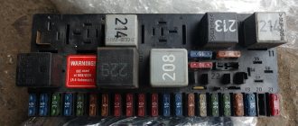
For Audi 80 to 91 years old, the fuel pump fuse is located at number 13 in the top row, its rating is 15 amperes. In total, the block contains 21 elements (models with a diesel engine have 22), and the wiring diagram also contains additional fuses used depending on the modification and configuration of the car.
Additionally, the mounting block contains the following relays:
- fuel pump relay;
- relay for fog lights and tail lights (if there are no fog lights in the package, then a jumper is installed in this place);
- starter relay;
- horn relay;
- turns relay;
- climate control relay;
- wiper relay;
- relay for headlight washer, fan, security system, etc.
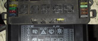
On the cover of the mounting block there is a detailed diagram of the arrangement of the elements, and a detailed explanation of all the elements of the block is in the operating manual for the Audi 80 b3.
For the Audi 80 B4 brand, the location of the mounting block is completely similar, with the exception of the total number of elements and their purpose. So, the fuel pump in b4 is connected to element No. 12, and the location of the relays also differs from their location on the block in model b3.
If a malfunction occurs with the electrical equipment of the car, you should first check the integrity of the fuses located in the engine compartment of the car. Even if the speedometer has stopped working, then with a high degree of probability the reason may be hidden in the fuses, especially since checking their integrity is much easier than disassembling the instrument panel and checking the speedometer directly for a malfunction.
Experienced drivers use the fuse responsible for the operation of the fuel pump as follows: often in winter, unsuccessful attempts to start the engine lead to the spark plugs being “flooded” with gasoline, as a result of which the car cannot be started. To dry the spark plugs, just remove the pump fuse from the block and turn the engine with the starter for a few seconds - the fuel supply will stop, and due to ventilation, the spark plugs will dry out quite quickly.
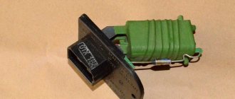
Resistor
A failed heater resistor is a fairly common problem among Audi 80 car owners.
At the same time, fixing such a breakdown yourself is not so difficult. There is no need to go to a car service center and pay someone money for a relatively basic repair. You just need a new resistor, as well as an understanding of the location of the desired object.
It is not difficult to determine that the heater on an Audi 80 does not work precisely because of a resistor failure. A clear sign of such a malfunction is the heater turning on exclusively at speed 4, while fan blowing modes 1, 2 and 3 do not turn on.
Yes, first of all it is recommended to check the condition of the contacts in the control unit, as well as the integrity of the wires. It cannot be ruled out that they are the problem. But if the check did not show any problems in the electrical circuit, then the problem is in the heater resistance resistor. It periodically burns out and therefore needs to be replaced.
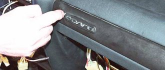
If we talk about the location, you will find the resistor directly on the electric motor of the stove. To access it you will need to open the glove compartment and remove it from the rails. In fact, getting to the resistor is extremely easy if you know how to remove the glove compartment.
You need to disconnect the connector with the wires and remove the resistor from the latches. The resistor fails due to the thermal fuse blowing. It needs to be replaced to restore the functionality of the element.
It's up to the motorist to decide, but Audi 80 owners usually use 2 methods:
- buy a new resistor and install it in place of the old one;
- restore the old resistance resistor through makeshift repairs.
Objectively, the best solution would be to purchase a new element that has a quality guarantee from the manufacturer. But this option is more financially expensive. And since it is important for many to save money, it is worth describing the option of repairing and restoring the resistor.
- Here you can take a piece of wire. But the option is not the best. It is preferable to use a simple 10 Amp fuse;
- Using wire cutters, the old fuse is bitten off, and a new 10-amp element is screwed in its place;
- Using copper wires in a protective sheath, as well as electrical tape, the contacts of the resistor are connected to the contacts of the fuse;
- Next, the assembly is assembled in the reverse order;
- The performance of the heater is checked at all speeds.
The experience of motorists shows that such a repair scheme for the heater resistance resistor on Audi 80 cars has every right to exist. But if in doubt, just buy a new resistor and change it according to the instructions. This is literally 10 minutes of your time.
Although fuses, relays and resistors are small parts of a car, they can play a key role in many issues. Including the performance of the heating system on Audi 80 cars in different bodies.
Moreover, checking the condition of the components considered is quite simple. The automaker has provided convenient access to the fuse box and resistor. Even the heater control unit is not as difficult to disassemble as some might think. A few latches and mounting screws separate you from it.
Source: remam.ru
Additional fuse block
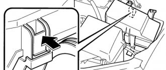
To gain access to the additional unit located inside the car, you need to unscrew the four screws securing the cover located under the steering wheel.
The configuration of the additional unit depends on the modification of the car, and often not all elements of the circuit may be used.
The additional unit is equipped with automatic fuses that turn off in the event of a short circuit in the network - after the fault is eliminated, they will automatically turn on.
The interior unit contains the following components of the vehicle's electrical circuit:
- common fuse;
- climate control or air conditioning control unit;
- control unit for automatic transmission and ABS system;
- control unit for electric motors of windows and sunroof;
- electronic engine control unit;
- control of heated driver and passenger seats (separate blocks for each seat);
- power seat controls;
- head light control system;
- interior lighting;
- seat belt and airbag controls;
- warning system for oil pressure, closed doors, etc.
Also in the wiring diagram there are unused elements (reserve), to which additional equipment can be connected: an amplifier for the speaker system, a security alarm, an electric trunk lock and other additional devices and electrical equipment.
Installing new devices or repairing electrical wiring in an Audi 80 should only be trusted to professionals - otherwise there is a high risk of the wiring catching fire.
If suddenly the fuses in the car have blown, you must first eliminate the cause of the malfunction, otherwise they will continue to burn.
You might find some videos helpful.
The new generation of Audi 80 b3 cars was introduced in mid-1986. Produced in 1987, 1988, 1989, 1990 and 1991. They were sold worldwide under the Audi 80 or Audi 90 brands (denoting higher-spec cars). The most common nickname in the CIS is “Bochka”. In our material you can find a detailed description of the relays and fuses on the Audi 80 90 b3 and their locations.
The tables provided are universal. On certain Audi 80 and Audi 90 models, some components or individual systems may be missing. It is also possible that the specified fuses and ratings may partially differ from the fuses installed on your machine. Refer to your description on the back of the protective cover.
- On-board computer/unit for automatic diagnostics of vehicle systems;
- Electronic fuel injection control unit or Motronic electronic control unit;
- Electronic air conditioning control unit;
- Vehicle position (height) sensor above sea level;
- Electronic ignition control unit;
- Buzzer for switching off automatic transmission mode;
- Air conditioner control panel;
- Power seat power relay.
- Electronic control unit for electric seats;
- Additional mounting block;
- Airbag activation unit;
- Airbag;
- Electronic control unit for automatic transmission;
- Hazard warning light (turn signal) breaker;
- Diagnostic system contact connectors;
- Contact connector for fog lights.
The Audi 80 b3 has two main relay and fuse blocks. One is under the hood, near the wipers. The second one is under the dashboard in the cabin.
Replacing fuses on Audi 80 B3
Preparatory stage:
- A set of new modules;
- Tweezers for removing fuses;
- Screwdriver, ratchet, 10" socket for unscrewing the board with modules.
Sequencing:
- We place the car on a flat surface, block the rear row of wheels with wheel chocks, and activate the parking brake to prevent arbitrary rollback;
- Open the hood, disconnect the terminals from the battery, unclip the plastic cover, under which the fuse board is located;
- On the back of the cover there is a marking and pinout for each module. We search by ordinal index and remove with plastic tweezers;
- We insert the new module into its original place and close the lid.
To dismantle the mounting block assembly, you need to unscrew two bolts, disconnect the connectors with wires, and then remove the entire board. We carry out preventive maintenance and install it back in its original place.
Since the Audi 80 B3 has pre-installed cylindrical modules, it is not difficult to distinguish a working one from a faulty one. In the first case, the melting element will be intact and not damaged.
Relay switches are preinstalled on top of the circuit board. To replace them, you need to disconnect the block with wires from the back.
Audi 80 B3 car owners practice converting the standard mounting block with a new one with pre-installed blade-type fuses.
The process is quite complex; it is difficult to re-equip the electrical power system yourself. You will need special equipment, wires, terminals, and contacts.
Fuse Maintenance Recommendations
- After driving through puddles or in the rain, check the mounting block for moisture. Dry, blow with compressed air as necessary. Do not allow condensation to accumulate in the plastic housing;
- Buy spare parts and consumables at certified points of sale, official representative offices, dealer centers;
- Do not install over- or under-current protection modules. This will lead to a decrease in the functionality of equipment, mechanisms, and units;
- Check the integrity of the fuses with special equipment - a multimeter. If necessary, contact service station specialists for help.
The average service life of fuses, relays - switches on the Audi 80 (B3) is 45 - 50 thousand km.
Tired of paying fines? There is an exit!
Forget about fines from cameras! An absolutely legal new product - Traffic Police Camera Jammer, hides your license plates from the cameras that are installed in all cities. More details at the link.
- Absolutely legal (Article 12.2);
- Hides from photo and video recording;
- Suitable for all cars;
- Works through the cigarette lighter connector;
- Does not cause interference to radios and cell phones.
Find out details
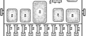
Relay mounting block in the cabin
Decoding for cars produced before 1989
| Relay No. in the picture above | Name |
| 1 | ABS relay |
| 2 | Seat belt warning relay |
| 3 | |
| 4 | A/C clutch relay |
| 5 | |
| 6 | Headlight relay |
| 7 | — |
| 8 | — |
| 9 | — |
| 10 | — |
| 11 | — |
| 12 | |
| 13 | |
| 14 | |
| 15 | Relay for electric sunroof and power windows |
| 17 | — |
| 18 | — |
Decoding for cars produced after 1989
| Relay No. in the picture above | Name |
| 1 | ABS relay |
| 2 | Seat belt warning relay |
| 3 | Interior lighting relay |
| 4 | A/C clutch relay |
| 5 | Windshield wiper/washer relay* |
| 6 | Headlight relay |
| 7 | |
| 8 | — |
| 9 | Automatic Shift Lock Relay |
| 10 | — |
| 11 | — |
| 12 | — |
| 13 | Front passenger seat heater relay |
| 14 | Driver Seat Heater Relay |
| 15 | Relay for electric sunroof and window lifts |
| 17 | Anti-theft warning light relay |
| 18 | Reverse current relay (electric seats and rear view mirrors) |
14.2.1.4. Identifying Contacts on the Fuse and Relay Box Boards
Identification of relay blocks (Audi-80/90)
| 1. Fog lights J5 2. Radiator cooling fan (stage 2) J101 3. Engine-off radiator cooling fan control unit J138 4. Not used 5. Load reduction relay J18 | 6. A/C fresh air blower J11 7. Horn J4 8. Jumper between pins 36 and 38 of manual transmission 9. Automatic transmission J60 10. Fuel pump J17 11. Radiator cooling fan (stage 1) J26 |
Identifying Contacts on the Fuse and Relay Box Boards
| RELAY BOX LOCATION | CONTACT NUMBER | NUMBER ON RELAY BOX | USAGE |
| 1 | 10 | 86 | Fog lamps |
| 11 | 30 | ||
| 12 | 85 | ||
| 13 | 87 | ||
| 2 | 14 | 30 | Radiator Cooling Fan High Speed Relay |
| 15 | 85 | ||
| 16 | 87a | ||
| 17 | 87 | ||
| 18 | 86 | ||
| 3 | 1 | 15 | Radiator cooling fan control unit when the engine is off |
| 2 | 30 | ||
| 3 | 31 | ||
| 4 | |||
| 5 | ST1 | ||
| 6 | |||
| 7 | 87 | ||
| 8 | |||
| 9 | |||
| 4 | Open | ||
| 5 | 24 | 30 | Load reduction relay |
| 25 | 85 | ||
| 26 | 87 | ||
| 27 | 86 | ||
| 6 | 58 | Air conditioner relay | |
| 28 | 86 | ||
| 29 | 87a | ||
| 30 | 30 | ||
| 31 | 85 | ||
| 7 | 32 | 87 | Sound signal device |
| 33 | 86 | ||
| 34 | 30 | ||
| 35 | 65 | ||
| 8 | 36 | 87 | Automatic transmission |
| 37 | 86 | ||
| 38 | 30 | ||
| 39 | 85 | ||
| 9 | 40 | 53e | Windshield washer and wiper switch |
| 41 | 53c | ||
| 42 | 31b | ||
| 43 | 15 | ||
| 44 | 31 | ||
| 45 | I | ||
| 10 | 46 | 15 | Fuel pump |
| 47 | T | ||
| 46 | 30 | ||
| 49 | L | ||
| 50 | 31 | ||
| 51 | 1 | ||
| 52 | 87 | ||
| 53 | |||
| 59 | |||
| 11 | 54 | 87 | Radiator Cooling Fan Low Speed Relay |
| 55 | 86 | ||
| 56 | 30 | ||
| 57 | 85 |
Identification of relay blocks (Audi-80/90, 80/90 Quattro and Coupe, starting from models 1989)
| 1. Fog lamps, J5 2. Not used 3. Engine off radiator cooling fan control unit, J138 4. Headlight washer system, J39 5. Load reduction relay, J18 6. Radiator cooling fan high speed relay, J101 | 7. Horn, J4 8. Jumper between manual transmission pins 36 and 38 8. Automatic transmission, J60 9. Windshield washer/wiper switch, J31 10. Fuel pump, J17 11. Radiator cooling fan low speed relay, J26 |
Identifying Contacts on the Fuse and Relay Box Boards
| RELAY BOX LOCATION | CONTACT NUMBER | NUMBER ON RELAY BOX | USAGE |
| 1 | 10 | 86 | Fog lamps |
| 11 | 30 | ||
| 12 | 85 | ||
| 13 | 87 | ||
| 2 | Open | ||
| 3 | 1 | 15 | Radiator cooling fan control unit when the engine is off |
| 2 | 30 | ||
| 3 | 31 | ||
| 4 | T | ||
| 5 | ST1 | ||
| 6 | |||
| 7 | 87 | ||
| 8 | |||
| 9 | |||
| 4 | 19 | 30 | Headlight washer system |
| 20 | 85 | ||
| 21 | 86 | ||
| 22 | 87 | ||
| 23 | |||
| 5 | 24 | 30 | Load reduction relay |
| 25 | 85 | ||
| 26 | 87 | ||
| 27 | 86 | ||
| 6 | 58 | 87 | Radiator Cooling Fan High Speed Relay |
| 28 | 86 | ||
| 29 | 87a | ||
| 30 | 30 | ||
| 31 | 85 | ||
| 7 | 32 | 87 | Sound signal device |
| 33 | 86 | ||
| 34 | 30 | ||
| 35 | 85 | ||
| 8 | 36 | 87 | Automatic Transmission Jumper (Manual Transmission) |
| 37 | 86 | ||
| 38 | 30 | ||
| 39 | 85 | ||
| 9 | 40 | 53e | Windshield washer and wiper switch |
| 41 | 53c | ||
| 42 | 31b | ||
| 43 | 15 | ||
| 44 | 31 | ||
| 45 | I | ||
| 10 | 46 | 15 | Fuel pump |
| 47 | T | ||
| 46 | 30 | ||
| 49 | L | ||
| 50 | 31 | ||
| 51 | 1 | ||
| 52 | 87 | ||
| 53 | |||
| 59 | |||
| 11 | 54 | 87 | Radiator Cooling Fan Low Speed Relay |
| 55 | 86 | ||
| 56 | 30 | ||
| 57 | 85 |
Fuse and relay block board, contacts for wiring connections
| A – Contacts for connecting the plug of the air conditioning system, color gray B – Contacts for connecting the plug of the front right wiring harness, color black C – Contacts for connecting the plug of the instrument cluster, color blue D – Contacts for connecting the plug of the front left wiring harness, color green E – Contacts for connecting the plug of the front left wiring harness, color yellow F – Contacts for connecting the plug of the instrument cluster, color brown G – Contacts for connecting the plug of the instrument cluster, color red | H – Contacts for connecting the plug of the rear wiring harness, color black I – Contacts for connecting the plug of the instrument cluster, color red J – Contacts for connecting the plug of the instrument cluster, color yellow K – Contacts for connecting the plug of relay 3, color black L – Contacts for connecting single plug (terminal 30), color clear M – Contacts for connecting a plug of non-standard equipment installed on request, color clear N – Not used O – Not used P – To fuse 20 |
| previous page14.2.1.3. Fuse locations and identification | next page 14.2.1.5. Additional relay block board |
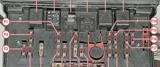
Central fuse distribution panel
This unit is located in the rear of the engine compartment.
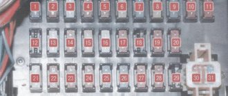
On the removed cover (7) of the central switch, a short form (6) shows the possible location of the relays and fuses. There are also small plastic pliers for disconnecting fuses. Inside the central switch, various relays (1), diagnostic plugs (2), fuses 1–21 (3), and additional fuses 23–32 (4) are visible. Next are four spare fuses (5).
Scheme
Table for Audi 80, 90 models up to 1989
| № | Current strength, A | Elements of the protected circuit |
| 1 | 15 | Fog lamps for headlights and rear lights |
| 2 | 15 | Hazard light breaker |
| 3 | 25 | Horn, brake lights |
| 4 | 15 | Interior lamps, luggage compartment lamp, Audi 80 90 cigarette lighter fuse, sun visor mirror lamp, on-board computer, radio |
| 5 | 30 | Engine cooling fan |
| 6 | 5 | Side and parking light bulbs for the right rear light |
| 7 | 5 | Lamps for parking light and left rear light |
| 8 | 10 | Right headlight high beam lamp, headlight high beam indicator lamp |
| 9 | 10 | Left headlight high beam lamp |
| 10 | 10 | Low beam lamp, right headlight |
| 11 | 10 | Left headlight low beam lamp |
| 12 | 15 | Instrument cluster, reverse lamps, on-board computer, self-diagnosis system unit, electronic anti-lock brake system control unit, electronic differential lock control unit |
| 13 | 15 | Fuel pump. |
| 14 | 5 | License plate, engine compartment and glove box lamps, instrument cluster lamps |
| 15 | 25 | Windshield wiper motor, engine cooling fan, A/C electronic control unit, turn signal lamps |
| 16 | 30 | Rear window defroster, rear view mirror defroster |
| 17 | 30 | Electric motor of the fan (supercharger) of the interior ventilation system |
| 18 | 5 | Electric rear view mirrors |
| 19 | 10 | central locking |
| 20 | 30 | Engine cooling fan switch (first stage), Electronic fan control unit when the engine is running |
| 21 | 25 | Rear cigarette lighter |
| 22 | — | — |
| 23 | 30 | Driver's seat adjustment motors, driver's seat position memory unit |
| 24 | 10 | Electronic control unit for KE-Jetronic or Motronic systems |
| 25 | 30 | Seat heaters |
| 26 | — | — |
| 27 | — | — |
| 28 | 15 | Motronic electronic control unit |
| 29 | 5 | Reserve |
Relay table
| Number | Name |
| I | Fog light relay |
| II | Engine cooling fan relay |
| (high speed) | |
| III | Cooling fan relay |
| engine when the engine is not running | |
| IV | — |
| V | Unloading relay |
| VI | Air conditioner relay |
| VII | Horn relay |
| VIII | Automatic transmission relay |
| IX | Windshield wiper and washer intermittent relay |
List for Audi 80, 90 models from 1989
1. Fog lights, rear fog lights 15 2. Hazard warning lights 15 3. Horn, heated seats 30 4. Clock, trunk light, vanity mirror, reading light, socket/cigarette lighter, trip computer, full automatic air conditioning, radio, auto-check system (Auto-Check-System) 15 5. Second stage cooling fan speed 30 6. Right tail light, front side light 5 7. Left rear side light, front side light 5 8. Right high beam, high beam indicator lights 10 9. Left high beam headlight 10 10. Right low beam, right headlight leveling motor 10 11. Left low beam, left left headlight leveling motor 10 12. Instrument cluster, reversing light, Auto-Check system -System), automatic transmission, differential lock, on-board computer, control system, speed control, interior lighting lamp with off delay, electronic thermal switch, operation of the cooling system fan after stopping the engine 15 13. Fuel pump 15 14. License plate lamp, lighting instruments, engine compartment lighting, glove compartment lighting, automatic air conditioning 5 15. Turn indicators, windshield wipers, windshield washer pump, heated windshield washer nozzles, cooling system fan (control unit for turning on the cooling fan after stopping the engine), air conditioning 25 16 Heated rear window, heated external rear view mirrors 30 17. Fan, automatic air conditioning 30 18. Electrically adjusted external rear view mirrors, rear window washer (station wagon) 5 15 19. Central locking system, heated door paint mechanism cylinders, alarm 10 20. First stage of the cooling system fan, turning on the fan after stopping the engine 30 21. Self-diagnosis / connecting a diagnostic tool 10 22. Free -
The electric beet lifts, electric sunroof and electric seat adjustment are equipped with automatic fuses that automatically switch on again after the fault has been corrected.
23. Free - 24. Free - 25. Lambda probe heating 5 26. Trailer socket 30 27. Ignition/injection system 10 28. Ignition/injection system 10 29. Brake light 10 30. 31. Cruise control combined with automatic transmission, ABS, differential lock 5 15 32. Ignition/injection system 10
Relay list
- Fog light relay;
- Spare;
- Cooling fan relay;
- Headlight washer relay;
- Unloading relay;
- Engine cooling fan relay;
- Horn relay;
- Automatic transmission relay;
- Relay for intermittent operation of the windshield wiper and washer;
- Fuel pump relay;
- Engine cooling fan relay.
14.2.1.3. Fuse locations and identification
Fuse locations and identification (Audi-80/90)
| N | Description | A. |
| 1 | Fog lamps and rear fog lamps | 15 |
| 2 | Alarm breaker | 15 |
| 3 | Horn, brake lights | 25 |
| 4 | Reading lights, luggage compartment lights, cigarette lighter, interior lights, makeup mirror lights, trip computer, radio | 15 |
| 5 | Fan, cooling radiator | 30 |
| 6 | Right side lamp, right parking lights | 5 |
| 7 | Left parking light, left parking lights | 5 |
| 8 | Right headlight high beam lamp, headlight high beam indicator lamp | 10 |
| 9 | Left high beam lamp | 10 |
| 10 | Low beam lamp, right headlight | 10 |
| 11 | Left low beam lamp | 10 |
| 12 | Instrument cluster, reverse signal lamps, automatic check system, vehicle motion control, ABS system, on-board computer differential lock devices, throttle valve injection timing control unit, electronic thermal switch, radiator cooling fan control unit | 15 |
| 13 | Fuel pump heating regulator | 15 |
| 14 | Glove compartment lamp, engine compartment lamp, license plate lamps | 5 |
| 15 | Windshield wipers, radiator cooling fan thermal switch, air conditioner pressure switch | 25 |
| 16 | Heated rear window, heated outside mirror | 30 |
| 17 | Fan blowing fresh air | 30 |
| 18 | Power mirrors | 5 |
| 19 | central locking | 10 |
| 20 | Fan, radiator cooling (step 1), radiator cooling fan control unit with engine off | 30 |
| 21 | Rear cigarette lighter | 25 |
| 22 | Not used | |
| 23 | Power seats with memory function | 30 |
| 24 | Motor control I | 10 |
| 25 | Heated seats | 30 |
| 26 | Not used | |
| 27 | Not used | |
| 28 | Engine Control II | 15 |
| 29 | Backup fuses (5A, 10A, 25A, 30A) |
Location and identification of fuses (Audi-80/90, 80/90 Quattro and Coupe, starting from models 1989)
| N | Description | A. |
| 1 | Fog lamps and rear fog lamps | 15 |
| 2 | Alarm breaker | 15 |
| 3 | Horn, brake lights | 25 |
| 4 | Reading lights, trunk lights, cigarette lighter, interior lights, makeup mirror lights, trip computer, radio, clock, automatic climate control, anti-theft alarm system | 15 |
| 5 | Fan, cooling radiator | 30 |
| 6 | Right side lamp, right parking lights | 5 |
| 7 | Left parking light, left parking lights | 5 |
| 8 | Right headlight high beam lamp, headlight high beam indicator lamp | 10 |
| 9 | Left high beam lamp | 10 |
| 10 | Low beam lamp, right headlight | 10 |
| 11 | Left low beam lamp | 10 |
| 12 | Instrument cluster, reverse lamps, automatic check system, vehicle motion control, ABS system, differential lock devices, on-board computer, electronic thermal switch | 15 |
| 13 | Fuel pump heating regulator | 15 |
| 14 | Glove compartment lamp, engine compartment lamp, license plate lamps, | 5 |
| 15 | Windshield wipers, thermal switch, radiator cooling fan, air conditioner, turn signal lamps | 25 |
| 16 | Heated rear window, heated outside mirror | 30 |
| 17 | Fan blowing fresh air, air conditioner | 30 |
| 18 | Power mirrors, rear window wiper (Coupe) | 5 |
| 19 | Central locking, heated locking system | 10 |
| 20 | Fan, radiator cooling (step 1), radiator cooling fan control unit with engine off | 30 |
| 21 | Diagnostic monitoring device | 10 |
| 22 | Not used | |
| 23 | Power seats with memory function | 30 |
| 24 | Not used | |
| 25 | Heated seats | 30 |
| 26 | Not used | |
| 27* | Engine Control I (from September 1987) | 10 |
| 28* | Engine Control II | 15 |
| 29 | Backup fuses (5A, 10A, 25A, 30A) |
| previous page14.2.1.2. Additional fuse holders | next page 14.2.1.4. Identifying Contacts on the Fuse and Relay Box Boards |
Additional Information
Check out this video. Here you can clearly see how to access the fuse panel in the B3 model.
If you want to know more, download a free book on repair and operation of the Audi 80 b3: ""
In order for your “iron horse” to always work properly, you need to periodically devote time to diagnosing it. This includes the electrical wiring of the vehicle. This material will help you find out where the Audi 80 fuses are located, what they are responsible for and how to change them if necessary.
A little about the electrical equipment of the Audi 80 b4
This car is of a later release, which means it is more advanced. It also has protective fusible links in the machine's electrical system. This model has a diagnostic connector in its electrical equipment. Service equipment is connected to it to service the machine. The Audi 80 b4 unit has 21 fuses, in models with a diesel engine there are one more, plus two additional devices.
There was also room in the block for installing 4 spare fuses. For ease of detection and replacement of a faulty fuse-link with a new one, the cover has symbols with consumers and the nominal value of the permissible current. There are also tweezers for convenient removal and installation of elements. In these models, the fuse box is also mounted in the engine compartment. If you look closely in the engine compartment, you can see a mounting block under the windshield.
Advice! Detection and replacement of a failed fuse in the Audi 80 unit is carried out with the engine turned off.
Before installing a new protective fusible link in the block, it is necessary to detect and then eliminate the cause of the failure of the Audi 80 fuse. Why is this necessary? Burnout of the fuse link is possible only when the current consumption is exceeded. It can occur after a short circuit in the consumer circuits, or when these consumers fail. If this problem is not corrected, the fuse links will burn out.
In conclusion, I would like to remind you once again that the fuse modules of different models are different. Thus, the Audi 80 b2 fuse box differs from models b3, b4.
In order for your “iron horse” to always work properly, you need to periodically devote time to diagnosing it. This includes the electrical wiring of the vehicle. This material will help you find out where the Audi 80 fuses are located, what they are responsible for and how to change them if necessary.
[Hide]
Location
Foreign-made vehicles are mostly equipped with many electrical appliances that require protection. This is what fuse blocks are used for - to protect equipment from overvoltage. Audi 80 b3 or b4 cars, like other foreign cars, are equipped with a fuse box and relay.
The block can be found in the engine compartment. After opening the hood, you will see the fuse block (hereinafter referred to as the fuse block), which is located under the windshield. It is hidden by a plastic cover designed to protect it from moisture and debris.
This fuse box contains 31 parts that protect the wiring circuits. There are also four spare components here. In addition, in this fuse block you can see a special connector, which is necessary to connect a tester for diagnosing the on-board computer. The fuse diagram and table of their assignments is given below.
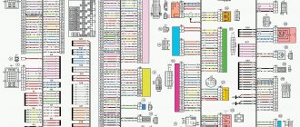
Power supply circuit
This scheme is relevant for Audi 80 b3 and b4 cars.
As noted above, in Audi 80 b3 and b4 cars, not only fuses, but also relays are responsible for the safety of devices. These components are responsible for the operation of the power windows, power sunroof, if equipped (depending on equipment) and the front seat adjustment devices. There is also a device responsible for the operation of the radiator fan of the cooling system.
FUSE BLOCK AUDI 80 B2 81,85,B2 SEDAN
To identify the vehicle and reliably select the fuse block Audi 80 B2 81.85,B2 Sedan , you should carefully select the vehicle modification.
To do this, use clarifying information with data containing: power, measured in horsepower (example 103 hp), engine size (example 1.6 liters), type (example gasoline) and model + engine code, as a rule, this parameter rarely used, but you can only find it in the vehicle title, you can also pay attention to the drive axle (there are rear, front or all-wheel drive), and a mandatory parameter is the release date, which divides the vehicle model into restyling, pre-restyling, first and last year production. This data serves to uniquely install spare parts during a certain production period, as manufacturers are constantly upgrading cars off the assembly line.
Purpose
Now let's move on to the purpose of the power supply components. The tables are presented below.
Regarding relays, this information will probably also be useful to you.
| Serial number | What protects |
| 1 | Ensures the safe operation of fog lamps and tail lights, as well as the bridge, if the vehicle is not equipped with fog lamps. |
| 2 | This part protects the cooling system fan from failure (relevant for vehicles not equipped with a climate control system). |
| 3 | Provides the functionality of the ventilated device activation control unit after the motor is turned off. |
| 4 | This device allows the headlight washer system to function safely. |
| 5 | X-contact relief component. |
| 6 | For vehicles with manual air conditioning, this component performs the function of protecting the fan circuit, and on cars with an automatic climate control system and some other engine variations, the sixth number designates the relay responsible for the operation of the second cooling system fan. |
| 7 | Responsible for the functionality of the steering horn. |
| 8 | This number allows you to ensure the functionality of the alarm system in Audi 80 cars equipped with a manual transmission. If your vehicle is equipped with an automatic transmission, this location will remain open. |
| 9 | Windshield wash intermittent component. |
| 10 | Gasoline pump Audi 80. |
| 11 | The first fan of the cooling system. |
Repair and maintenance book
Central switch Audi 80
The central switch is located in the Audi 80 in a waterproof casing under the windshield. It can contain up to 31 fuses (one more if the car has a diesel engine), four spare fuses and a total of eleven relays. In addition, there is also a plug connection for connecting a diagnostic device.
- Relay for fog lights and rear parking lights, bridge, if the car is not equipped with fog lights;
- Cooling system fan relay (models not equipped with air conditioning), relay for the second cooling system fan;
- Control unit for turning on the fan after stopping the engine;
- Headlight cleaning system control unit;
- X-contact unloading relay.
- Fan relay (on models with manual air conditioning), second cooling fan relay (on models with automatic air conditioning and some engine options);
- Horn relay;
- Alarm system relay (on models with a manual transmission), bridge on models not equipped with an alarm system. On models equipped with automatic transmission, this space remains empty;
- Intermittent wiper/wash system relay;
- Fuel pump relay;
- Relay for the first cooling fan.
AUDI 80 B4 fuel pump relay
Where is the fuel pump relay located or what to do if the fuel pump does not turn off.
Audi 90 starter does not turn on. Replacing the ignition switch contact group.
If the ignition switch does not work, you do not need to change the lock completely, just replace the contact group...
All wires in the Audi 80 are collected in various bundles. They all end in the so-called central commutator, a black box located at the rear left of the engine compartment in a waterproof casing. It can accommodate 21 fuses, ten additional fuses, four backup fuses and a whole range of relays.
Replacing the central switch
If, during troubleshooting, it is discovered that the cable connections and the corresponding fuse or relay are not damaged, then the central switch may also be the cause of the malfunction. Typical failures may include loose connections or temperature-related failures. In this case, you need to replace the central switch.