03/30/2021 10,663 VAZ 2110
Author: Ivan Baranov
The ECU is the main control module in any car. Thanks to the control unit, the optimal parameters for the operation of the power unit are determined, so this module must always work exactly like a clock. Where is the VAZ 2110 ECU located, what malfunctions are typical for it and how to change the device if necessary - we will talk about this below.
[Hide]
Where are the VAZ 2110 ECUs (the brains of the car)
If you are wondering where the ECU (the brains of the car) is located on the VAZ 2110, you can look at these photos where it is located ↓
Removable plastic and brains directly under the instrument panel, namely in its lower part.
In the depths of the wiring and bundle of wires and relays with fuses, you can find the controller itself, which is screwed in a horizontal position on the bar.
Description of "brains"
The VAZ 2110 is considered the first vehicle in the domestic automobile industry equipped with an injection engine. The power unit is controlled by an ECU, an electronic device that determines the basic parameters of engine operation in accordance with sensor signals. In fact, the ECU of a VAZ 2110, VAZ 2112 or any other model is the “brains” of the car, the operation of which affects the functionality of the vehicle as a whole.
Control controller in VAZ 2110
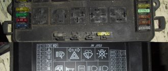
In the “Tens”, as well as the VAZ 2112, there are 16 valves and other models equipped with BOSCH 7.9.7 or January 7.2 systems, one M6 screw is installed in the head. From this screw the mass is taken to the ignition coils, and the mass is taken directly to the control model in the cabin. Typically, the mass is a welded stud mounted on the ECM bracket, particularly behind the center console, behind the left screen. In this case, the mass is transferred to the bracket through a pin, which is welded on the engine shield in the middle. It should also be noted that the nut on this stud is not usually tightened.
Control unit location
Now let's consider the location of the VAZ 2110 ECU. This device in the Ten is located under the center console, in its lower part, in particular, under the control panel. In order to gain access to the control module, you must remove the plastic panel on the passenger side, to do this you will have to use a Phillips screwdriver. Once you remove the cover, you will see many different wires, plugs, and safety devices. The controller itself is located behind them, it is screwed to the bar in a horizontal position.
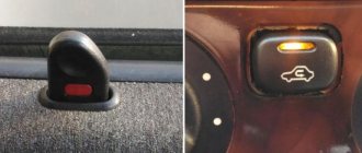
The arrow indicates the location of the ECM module behind the center console
Typical malfunctions: their symptoms and causes
If the electronic engine management system malfunctions, this can lead to problems with the operation of the power unit. Unfortunately, ECU malfunctions in dozens of domestic cars are not uncommon, so the car owner should be aware of the main problems, as well as the reasons for their occurrence.
First, let's look at the symptoms of malfunctions:
- There is no connection with the diagnostic tester. If problems begin to appear in the operation of the engine, the car owner can diagnose the performance of the power unit using a tester or laptop. But if the ECU does not work, then when trying to contact the on-board computer, the car owner will see that there is no connection.
- The ECM does not receive signals about the operation of the injectors, ignition system, fuel pump, valve or idle speed sensor. There may also be no signals from other actuators.
- Another sign is the lack of response to the oxygen sensor, engine temperature controller, throttle position sensor and other controllers.
- Mechanical damage to the device can also be a sign of failure. Cracks may appear on the case as a result of strong mechanical impact; radio elements or conductors could burn out (the author of the video about the repair is Pavel Ksenon).
As for the reasons, malfunctions in the electronic control unit can occur as a result of:
- Unskilled intervention. This reason is one of the most common. If a car owner independently carries out electrical repairs or installs an anti-theft system, or entrusts this work to unqualified craftsmen, errors may be made in the process.
- A common problem is lighting a car battery from a vehicle with the engine running. When lighting the engine, the engines of both cars must be turned off, otherwise there is a risk of brain damage, this is important to remember.
- Another problem that does not occur so often is polarity confusion when connecting a car battery. If you confuse plus with minus, it can not only damage the control unit, but also damage the battery itself, which can lead to expensive repairs.
- The reason may be that the battery terminals are disconnected while the engine is running.
- Also, the control unit may fail as a result of turning on the starter unit with the power bus disconnected.
- The engine control system can be damaged if an electrode accidentally hits the sensor or vehicle wiring during welding work.
- One of the most serious problems is water getting into the ECU. If liquid gets into the device, the board itself may become covered.
- A break in the electrical circuit or a short circuit in the wiring.
- The cause may also be malfunctions in the high-voltage component of the ignition system. For example, a breakdown of the ECU can be caused by a failure of the coil, high-voltage cables, distribution mechanism, etc.
Pinout of contacts on the controller
Instructions for removing and replacing the computer
The need to dismantle the ECM unit 16 of the ten valve engine arises if repairs are necessary when faults are identified. The repair process itself will depend on what exactly happened in the operation of the ECU. For example, if the contacts on the module connector have oxidized, the unit must be dismantled to clean or replace them. If the reason lies in damage to the housing, then the device must be removed for replacement; if water has gotten inside, then the module should be removed in order to dry it. Only after you have dried the block can it be tested.
If the problem lies in the performance of the board and some burnt-out elements, then you can try to repair it yourself by re-soldering some components. But we would still recommend turning to specialists for help, especially if you have never encountered such a problem before (the author of the video about repairing the control controller is Vyacheslav Chistov).
Payment via Yandex Cashier
After selecting payment via Yandex, the Yandex Cashier payment system will launch, where you need to select a convenient payment method (bank card, QIWI, Yandex Money account, etc.)
After specifying payment details and confirming payment, payment for the goods will occur.
If you have a bank card in a currency other than the ruble, then the money will be debited from the card at the rate of the Central Bank of Russia at the time of the purchase.
This payment method is optimal for residents of Russia, Kazakhstan and Belarus.
Official website of the Yandex Kassa payment system https://kassa.yandex.ru
Replacement of the electronic control unit of VAZ Lada 2110 in auto repair shops in Moscow
15 car repair companies
- Afto-service
- st. Polikarpova, 27, building 3
- +7 (495) 99… show all
- The site of the company
- Stomobil
- Lr-technik
- Apollo Motors
- Dvs
- Tiger box
- London-auto
- Gag-auto
- RF-motors
- Autoelite service
- Tigerboxru
- Apollo Motors
Popular companies
Causes of poor headlights
This is what we should strive for
You need to look for the reason:
- Faulty lamp.
- Dirty glass.
- damaged or peeling reflector.
- Insufficient voltage.
- The direction of the light flow is not adjusted.
Replacing a dim lamp
The lamp is replaced with a screwdriver (thin) or an awl. The protection box is removed by unscrewing the screws on the headlight unit. Under the cover you can see the holder mechanism and the three-pin block.
Changing the lamp
The procedure begins by disconnecting the terminal block . Next, pressing on the fastening spring, the lamp is removed and then replaced. At the same time, condensation is removed from the reflector block. The presence of this disables the lighting device. Moisture is removed through the drainage duct, after preliminary cleaning. Installation of the lamp, assembly is carried out in the reverse order.
Dirty headlights and cloudy windows
Dirty headlights reduce road illumination by 50%! Moreover, glass ages and becomes cloudy over time. Wiping with a dirty cloth contributes to this, which causes microscopic scratches.
The brightness of the car light is 50%! Depends on the condition of the headlight glass
We recommend: Fuel filters for VAZ 2110–2112: do-it-yourself replacement
It is possible that there are cracks that allow dust particles and water to pass through (during washing). They settle on the outer and inner surface of the glass, the reflector and lead to low transmission of light rays.
An irreparable mark on the glass is left by specks of dust, grains of sand, and pebbles flying out from under the wheels of oncoming or passing cars. Scratches and microcracks refract and scatter light in different directions , as a result of which the direction of the beam is lost.
Replacing glass in headlights
The option of gluing with transparent film is not a technical solution. The obvious solution is to replace the glass.
Lamps and glass cannot produce any effect if the reflector has peeled off due to prolonged use. On domestic VAZ-2114 cars, it is possible to replace the reflector, for which you should:
- Disconnect the battery and remove the headlight unit (see “Removing the headlight on a VAZ-2114”).
Front view, headlight mounts
- Remove the glass from the sealant, having previously heated it with a household heating element, if there is no construction heating element.
Unfasten the fastening latches and, cutting off the layer of sealant, remove the glass
- Unscrew the lamp, remove the defective reflector, replacing it with a new one. Fresh sealant is applied to the grease-free ends of the glass and the assembled headlight is mounted in place.
We mount the assembled headlight in place
Lamp voltage low
Low voltage at headlight terminals can cause dim light
Low voltage occurs due to a malfunction of the current generator, oxidation or broken contacts . When checking this unit, you need to ensure that the voltage, including at the lamp contacts, is 13.8÷14.2 V. Low voltage can be detected by ringing the circuit and finding a defect and eliminating it.
A typical cause of dim headlights is often the xenon lamps used on the car.
Distorted headlight position
The wrong direction of the beams is due to the distorted position of the headlights.
This happens as a result of a minor impact, even a light touch of the bumper, for example, with a wall when parking, a tree or a curb.
Adjusting the headlights is accompanied by placing the car on a flat area in front of a smooth wall at a distance of 7–10 meters. The accuracy of the direction of the rays can be obtained provided that the tank is filled (more than 50%!) and tires are inflated to the required standard. The machine is loaded as it is normally used.
Two headlight adjustment screws
On the wall, draw with chalk the center of one headlight (the other is covered, for example, with a piece of cardboard) and the center of the body. A second line is made 12 cm lower. The third line is drawn 22 cm below the first. Based on these three projections, a vertical line is drawn covering the center of the headlight and the body. One of the two screws located inside the headlight adjusts the tilt of the light, and the second forms a directed beam .
Turning on the low beam will result in a projection on the second line. Having completed the procedure with the second headlight, you get an adjusted low beam. In this case, the high beam will also be adjusted.
Common VAZ 2110 ECU errors
Decoding the error code of the ECU on the VAZ 2110: 0102 - Low signal level of the mass air flow sensor 0103 - High signal level of the mass air flow sensor 0112 - Low level of the intake air temperature sensor 0113 - High level of the intake air temperature sensor 0115 - Incorrect signal of the coolant temperature sensor 0116 - Invalid coolant temperature sensor signal 0117 - Low coolant temperature sensor signal 0118 - High coolant temperature sensor signal 0122 - Low throttle position sensor signal 0123 - High throttle position 0130 - Invalid sensor signal oxygen sensor 1 0131 - Oxygen sensor signal low 1 0132 - Crankshaft sensor signal high 1 0133 - Oxygen sensor slow response 1 0134 - No oxygen sensor signal 1 0135 - Oxygen sensor heater fault 1 0136 - Oxygen sensor 2 short to ground 0137 - Low Oxygen sensor 2 signal level 0138 - Oxygen sensor 2 signal high 0140 - Oxygen sensor 2 open 0141 - Oxygen sensor 2 heater malfunction 0171 - Mixture too lean 0172 - Mixture too rich 0201 - Injector 1 control circuit open 0202 - Injector 2 control circuit open 0203 - Open injector control circuit 3 0204 - Open injector 4 control circuit 0261 - Short to ground in the injector 1 circuit 0264 - Short to ground in the injector 2 circuit 0267 - Short to ground in the injector 3 circuit 0270 - Short to ground in the injector 4 circuit 0262 - Short to ground +12V injector 1 circuit 0265 — Short to +12V injector 2 circuit 0268 — Short to +12V injector 3 circuit 0271 — Short to +12V injector 4 circuit 0300 — Many misfires 0301 — Misfires in cylinder 1 0302 — Misfires in 2 cylinder 0303 - Misfire in cylinder 3 0304 - Misfire in cylinder 4 0325 - Open circuit of knock sensor 0327 - Low signal level of knock sensor 0328 - High level of knock sensor signal 0335 - Incorrect signal from crankshaft position sensor 0336 - Error in signal from crankshaft position sensor 0340 — Phase sensor error 0342 — Low phase sensor signal 0343 — High phase sensor signal 0422 — Low converter efficiency 0443 — Malfunction of the canister purge valve circuit 0444 — Short or open canister purge valve 0445 — Short to ground canister purge valve 0480 — Malfunction chain strength cooling fan 1 0500 - Incorrect speed sensor signal 0501 - Incorrect speed sensor signal 0503 - Interruption of the speed sensor signal 0505 - Idle speed controller error 0506 - Low idle speed 0507 - High idle speed 0560 - Incorrect on-board voltage 0562 - Low on-board voltage network 0563 - High voltage on-board network 0601 - ROM error 0603 - External RAM error 0604 - Internal RAM error 0607 - Malfunction of the detonation channel 1102 - Low resistance of the oxygen sensor heater 1115 - Faulty oxygen sensor heating circuit 1123 - Rich mixture in idle mode 1124 - Lean at idle 1127 - Rich at Partial Load 1128 - Lean at Partial Load 1135 - Oxygen sensor heater circuit 1 open, short 1136 - Rich at Light Load 1137 - Lean at Light 1140 - the measured load differs from the calculation of 1171 - the low level from the potentiometer 1172 - the high level from the potentiometer 1386 - the error of the detonation channel test 1410 - the adsorber purge control circuit short circuit for +12V 1425 - the adsorber blowing valve short -shorting for Earth 1426 - circuit - circuit - circuit control circuit of the canister purge valve open 1500 - Open circuit of the control circuit of the fuel pump relay 1501 - Short to ground of the control circuit of the fuel pump relay 1502 - Short circuit to +12V of the control circuit of the fuel pump relay 1509 - Overload of the control circuit of the idle speed regulator 1513 - Circuit of the idle speed regulator short circuit to ground 1514 - Idle speed control circuit short circuit to +12V, open 1541 - Fuel pump relay control circuit open 1570 - Incorrect APS signal 1600 - No communication with APS 1602 - Loss of on-board power supply voltage to the ECU 1603 - EEPROM error 1606 - Rough road sensor incorrect signal 1616 - Rough road sensor low signal 1612 - ECU reset error 1617 - Rough road sensor high signal 1620 - PROM error 1621 - RAM error 1622 - EPROM error 1640 - EEPROM Test error 1689 - Invalid error codes 0337 - Crankshaft position sensor, for mooing to ground 0338 - Crankshaft position sensor, open circuit 0441 - Air flow through the valve is incorrect 0481 - Cooling fan 2 circuit malfunction 0615 - Starter relay circuit open 0616 - Starter relay circuit short circuit to ground 0617 - Starter relay circuit short circuit to +12V 1141 - Malfunction oxygen sensor heater 1 after the converter 230 — Fuel pump relay circuit malfunction 263 — Injector driver 1 malfunction 266 driver 2 malfunction 269 — Injector driver 3 malfunction 272 — Injector driver 4 malfunction 650 — CheckEngine lamp circuit malfunction
Description
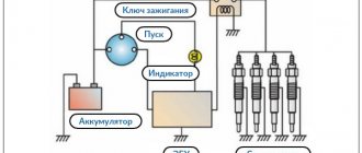
Fuel injection system diagram
1 – air filter; 2 – mass air flow sensor; 3 – inlet pipe hose; 4 – coolant supply hose; 5 – throttle pipe; 6 – idle speed regulator; 7 – throttle position sensor; 8 – channel for heating the idle system; 9 – receiver; 10 – pressure regulator hose; 11 – controller; 12 – relay for turning on the electric fuel pump; 13 – fuel filter; 14 – fuel tank; 15 – electric fuel pump with fuel level sensor; 16 – drain line; 17 – supply line; 18 – pressure regulator; 19 – inlet pipe; 20 – injector ramp; 21 – nozzle; 22 – speed sensor; 23 – oxygen concentration sensor; 24 – gas inlet of the muffler exhaust pipe; 25 – gearbox; 26 – cylinder head; 27 – outlet pipe of the cooling system; 28 – coolant temperature sensor; A – to the supply pipe of the coolant pump
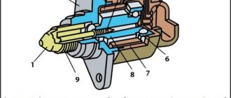
Controller 2110
1 – programmable read-only memory (PROM)
The controller (Fig. Diagram of the fuel injection system) (electronic control unit), located under the instrument panel console, is the control center of the fuel injection system. It continuously processes information from various sensors and controls systems that affect exhaust emissions and vehicle performance.
The controller receives the following information:
- about the position and speed of the crankshaft;
- about engine air mass flow;
- about the coolant temperature;
- about the throttle position;
- about the oxygen content in the exhaust gases (in a feedback system);
- about the presence of detonation in the engine;
- about the voltage in the vehicle’s on-board network;
- about the speed of the car;
- about the position of the camshaft (in a system with sequential distributed fuel injection);
- about a request to turn on the air conditioning (if it is installed on the car).
Based on the information received, the controller controls the following systems and devices:
- fuel supply (injectors and electric fuel pump);
- ignition system;
- idle speed regulator;
- adsorber of the gasoline vapor recovery system (if this system is on the car);
- engine cooling fan;
- air conditioning compressor clutch (if the car has one);
- diagnostic system.
The controller turns on the output circuits (injectors, various relays, etc.) by connecting them to ground through the output transistors of the controller. The only exception is the fuel pump relay circuit. The controller only supplies +12 V to the winding of this relay.
The controller has a built-in diagnostic system. It can recognize system malfunctions, warning the driver about them through the “CHECK ENGINE” indicator lamp. It also stores diagnostic codes that indicate areas of trouble to help technicians make repairs.
Controller memory.
The controller has three types of memory: random access memory (RAM), once-programmable read-only memory (EPROM), and electrically programmable memory (EPROM).
The random access memory is the “scratchpad” of the controller. The controller microprocessor uses it to temporarily store measured parameters for calculations and for intermediate information. The microprocessor can input or read data into it as needed.
What types of ecu 2110 are there?
ECU Bosch M1.5.4
ECU VAZ 2110 January 5.1
ECU VAZ 2110 BOSCH MP7.0H
Where is the VAZ ECU located and the interchangeability of control units
First of all, to determine the type of control unit, you need to find its installation location in the car. To do this, you should study the manual. As an example, let's look at the VAZ 2108 - 2115. On these cars, the ECU is located in the passenger compartment, on the front right, slightly below the glove compartment.
By the way, this information is also useful for computer diagnostics, since you need to know where you can connect to the diagnostic connector installed in various places on a particular model.
Diagnostic connectors VAZ 2108 - 21099 with a low panel are located near the ECU, under the glove compartment. Models VAZ 2108 - 21099 with a high panel, as well as 2113 - 2115, have a connector inside the center console. The VAZ 2108 - 2115 version with the so-called Europanel has a connector on the panel, and it is located closer to the passenger door.
- As for the units themselves, VAZ 2108 - 2115 of different years of production have different ECU models. For example, the most popular ECU January 4 was installed on early models of injection engines with central injection into the intake manifold.
Version January 5 - 6 are ECUs with distributed injection, but without oxygen sensor support. The January 7 control unit has appeared on cars since 2007, supports all sensors, and effectively controls the engine.
Let us also add that in addition to January, different generations of GM units were actively used at VAZ, being an analogy of January 4 - 7. The same can be said about Bosch or Itelma ECUs. Taking into account all the features, interchangeability is possible, but you need to select analogues that are suitable for the class, version, number of supported sensors, etc.
The fact is that each model is only suitable for a certain combination of engine and sensors, as well as wiring and firmware. This means that different models, even within the same family, can only be installed taking into account full compatibility.
Let us note once again that the types of ECUs on VAZs differ. It turns out that you cannot put January 5.1 instead of January - 4 or GM-09 SAMARA, however, for January 5.1 there is interchangeability with VS (Itelma) 5.1 or Bosch M1.5.4. In turn, the Bosch M7.9.7 ECU is not compatible with previous units, but can be replaced with January 7.2 Itelma or Avtel.
To accurately identify the ECU, just remove the instrument panel frame from the side and write down the ECU number. Also, if you have a BC, you can optionally view the version and type of the ECU, as well as the firmware number of the unit
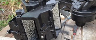
Location of the radiator of the VAZ 2110 stove
Heating equipment VAZ 2110 performs two main functions: cooking and heat distribution.
The preparation is carried out by a thermal unit, simply called a stove. It is located under the hood on the wiper side.
The radiator occupies a horizontal location under the panel. The controller maintains the flow rate and coolant temperature, guided by the position of the instrument panel controls and information from the ceiling sensor.
Location of the heater radiator
The left edge of the blue sector of one indicates a closed damper, the right edge of the red stripe corresponds to an open state. The second handle sets the fan operating modes.
Cabin air ducts distribute heat. The upper nozzles blow on the windshield, front door glass, and are located along the edge of the dashboard. The lower channels are directed under the feet of the driver and passengers.
VAZ ECU (brains)
Quite often, owners of domestic cars are forced to replace the engine ECU due to antifreeze getting into the control unit. Reset, reset error check, reset To replace it, clamp the latch and lift the bracket connecting the block and the wires. Next, using a “10” socket and an extension, unscrew the bolt securing the engine control unit to the battery platform. We also unscrew the bolt securing the block bracket to the mudguard. Next, we take the new engine control unit and install it in the bracket, after which we assemble the entire structure in the reverse order. Brain transfer on Kalina, detailed description: Why in a standard place I recently noticed a pattern in my Lada Kalina that when driving fast, the ECU engine control unit remembers my driving style and adapts to my driving style.
Removal and replacement of ECUs on VAZ 2110, 2111 and 2112 vehicles
So, the first thing you need to do is disconnect the negative terminal from the battery. Now it's worth noting that to do this simple job you will need the following tool:
- Socket head for 10
- Ratchet handle
- Phillips blade screwdriver
When you get to the engine control unit, you need to disconnect the plug with the wiring harness from it, after opening the metal latch:
Now you need to unscrew the two nuts securing the “brains”, as shown in the photo below:
When these two nuts are unscrewed, you need to slightly move the bar to the right to release it from its engagement:
After which you can carefully remove the ECU:
It is worth noting that if the controller fails, a new one must be installed the same as it was before - from the factory. The price of new controllers can range from 4,500 to 10,000 rubles, depending on the type and year of manufacture of the car. Installation is carried out in reverse order.
We flash the ECU on a VAZ 2110 with our own hands
It is often necessary to flash the brains of a car in order to remove certain problems in the car; read below on how to do this:
- You need to buy or download a free one: K-line Adapter (for example MasterKit or Romocable, any other) Battery or power supply (12V), Program (in our case winfe_1.13) Author's (or stock) firmware is up to you to decide, in my opinion case i205LR54_v7.3.bin
- Remove the block for easier work on the table. PS DON'T FORGET: Remove the ground terminal from the battery, and only then the connector from the ECU
- Connection diagram to the ECU
Connection diagram to the ECU - 51.53 ECU contact - Ground 71 ECU contact - K-Line (adapter for programming is connected here) 13 ECU contact - Ignition on (+12V) 12 ECU contact - Unswitched power supply (+12V) 43 ECU contact - Programming permission (+12V, through a resistor of about 4KOhm) 44.63 ECU contact - Main relay power supply (+12V)
- For connection you can purchase such a connector
- Now that everything is prepared. Let's move on to the winfe_1.13 program (the program works both from Win XP and from Win 7). Open the program. Select January 7.2 Set the Port (Click and select the one with the Adapter). Set the speed to 57600
- Everything is connected, configured, the program is open, turn on the power to pin 13, wait 30 seconds, the message “Communication with the ECU” should appear, if it doesn’t appear, turn off the power for 5-10 seconds and turn it on again. If it doesn’t appear, check that the connection is correct!
- Once the connection appears, click on the “ECU Programming” button and select your Decrypted firmware in the “bin” format; it should weigh 64 kbytes! If it weighs less (or the program does not understand it), then it must be decrypted with the Enigma program.
- We go and click Unpack firmware, select your encrypted one, Enigma Decrypts it! Next, we again select our decrypted firmware and wait for it to upload. We don’t touch EEPROM. Disconnect, go install. After reprogramming the unit, resetting the controller with clearing the self-learning memory (initialization) is MANDATORY!
Video “No spark and blown fuse - repairing the ECU”
What to do if there is no spark and the fuses are constantly blowing - the video below shows the process of repairing the control controller in a garage (the author of the video is the Auto Practice channel).
I came across an article by McSystem. Actually, here it is below
In January - about Januarys. Again and in detail about the ECM-ECU masses
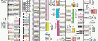
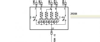
So, on to the topic! Classic ECM 21124 with ECU January 7.2(+) or M7.9.7 Electrical connection diagram of ECM EURO-2 M7.9.7, January 7.2 LADA 2110 with engine 21124. 21124-1411020-30, 21124-1411020-31.32
Fig. 1 ECM 21124 January 7.2, M7.9.7 Noticed, often described and characteristic problems - unstable idle speed, freezing speed, “jerking” of the engine at start and operation of the cooling fan, unreasonable jumps in the electrical parameters of the ECM during diagnostics. And this is not the entire list. And the whole problem is a rather incorrect wiring of the harness masses, not in relation to the body, but to the ECU. Therefore, in this article you will not see recommendations for tightening the “hoses” of additional mass to the ECU, due to its complete uselessness. This is not a newfangled “razmasovka” or “razminusovka”... Don’t get your hopes up!
The main idea voiced by the authors is that the wiring of the power lines of the ECU and fan and low-current sensor masses is fundamentally incorrect. Rice. 12
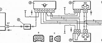
Fig.2 Ground connections of the ECM. S6, S7, S8
The sensors must be connected to the ground bus of the ECU board and not have contact with the body! There should be no flow of pulsed and direct currents of the ECU and IM in the sensor mass circuit. And the ECU is securely connected to the body. The rationale is to eliminate the influence of ECU currents (pulse and constant) and fan current on the reliability of sensor readings. Classic approach with data collection and processing systems! But not from AvtoVAZ designers, as usual... Now, in order
Fig. 3 Masses according to AvtoVAZ, or how not to do it
Electronic engine control unit (ECU, ECM, controller)
Delivery across Russia. We are pleased to announce a new product that is expected to be on sale by the end of February. These are new high quality running lights for Lada Largus. This fall, a new aerodynamic body kit for the Lexus RX “ATAGO” entered the auto tuning market; now you can buy it in our online store. This article will discuss exactly that.
How to flash a VAZ Many car owners are interested in how to flash a VAZ, change the “brains” of the car, make it more sporty.
Problems when paying with bank cards
Sometimes difficulties may arise when paying with Visa/MasterCard bank cards. The most common of them:
- There is a restriction on the card for paying for online purchases
- A plastic card is not intended for making payments online.
- The plastic card is not activated for making payments online.
- There are not enough funds on the plastic card.
In order to solve these problems, you need to call or write to the technical support of the bank where you are served. Bank specialists will help you resolve them and make payments.
That's basically it. The entire process of paying for a book in PDF format on car repair on our website takes 1-2 minutes.
If you still have any questions, you can ask them using the feedback form, or write us an email at
Phase sensor
As for this regulator, it is only present on a car with 16 valves. Its task is to provide information that will allow you to understand where and when to inject fuel into which cylinder.
Installation location
If the sensor fails, nothing particularly terrible will happen from the point of view of the integrity of the car. But fuel consumption will increase sharply.
We have not touched on all the signs, but we will try to talk about many of them in our special materials.
To understand how to repair your VAZ 2110, we recommend that you first study the operating manual in detail. It says about all the sensors, their tasks, location and, of course, replacement methods. Often, car owners ignore the manufacturer’s recommendations, although it is he who knows better than others how to perform this or that type of repair, preventive maintenance, and how to get to a certain unit, the same sensor, with minimal effort.