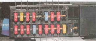
Mazda 6 GG fuse diagram under the hood
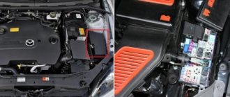
First, let’s clarify where the block with the protective elements of the Mazda 6 GG electrical network is located in the engine compartment.
Mazda 6 GG fuses and relays are mounted on the left wing of the Japanese car, next to the battery.
Fuse links in the engine compartment of the first generation Mazda 6 are responsible for the reliable and safe operation of the following devices:
- 1, 2, 3, 21, 35 – not used (spare);
- 4 – heating system for external mirrors (7.5A);
- 5, 22 – socket (5, 40A);
- 6 – power unit ECU (15A);
- 7 – Mass air flow sensor, power unit ECU;
- 8 – oxygen sensor (15A);
- 9, 10 – Mazda 6 1st generation low beam fuse for the right and left headlights (15A);
- 11, 12 – high beam front optics on the left and right;
- 13 – accelerator position controller (7.5A);
- 14 – emergency stop light warning;
- 15 – brake lights (15A);
- 16, 17 – control program of the internal combustion engine and automatic transmission (7.5A);
- 18 – fuel pump fuse Mazda 6 GG (20A);
- 19, 37 – additional electrical circuits (40, 15A);
- 20 – electric window lifts (30A);
- 23 – control unit of the heating complex, reversing lights (30A);
- 24 – heating radiator fan (40A);
- 25 – central locking Mazda 6 GG, interior lighting (40A);
- 26 – heating system (20A);
- 27 – rear glass heating system (40A);
- 28 – additional electrical circuits, ABS (60A);
- 29, 30 – auxiliary electrical circuits, air conditioning fan (30A);
- 31 – dashboard lighting, dimensions;
- 32 – interior lighting;
- 33 – electromagnetic type coupling;
- 34 – multimedia complex (15A);
- 36 – circuit for opening the fuel tank hatch (7.5A);
- 38 – cleaning mechanism for optics (20A);
- 39 – fog lights (15A);
- 40 – main fuse-link.
To ensure protection of electrical equipment along the block circuits in the engine compartment of a Japanese car, fuse links with a rated current of ten amperes are most often used. These include elements with serial numbers 7, 11, 12, 14, 16, 31, 32, 33, 40.
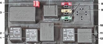
Relay unit under the hood
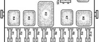
The Mazda 6 GI power unit of the engine compartment is equipped with the following relays:
- 1 – main fuse link Mazda 6 GG;
- 6, 8, 10, 18 – radiator cooling fan No. 2, 3, 4, 1;
- 7 – sound signal;
- 9 – starter relay;
- 11 – subwoofer;
- 12 – rear glass heating complex;
- 13 – PTF;
- 14 – air conditioning control program;
- 15 – main relay;
- 16 – optics;
- 17 – side lights;
- 19 – washing optics complex;
- 20 – PTF.
Fuse box under the hood
| Fuse | Terminal | Current (A) | Purpose |
| Fog lights | |||
| Driving lights | |||
| Brake lights | |||
| Additional light (overlays) | |||
| Engine control system | |||
| Warning FL Washers, Turn Signal Lights | |||
| ABS, Dynamic Stability Control | |||
| Audio system second option | |||
| Bose® Audio System (if equipped) | |||
| Audio system first option | |||
| Fuel system, fuel pump | |||
| Headlight right (RH) *1 , Daytime running lights | |||
| Horn, horn | |||
| Tail lights, license plate lights, parking lights, front side marker lights | |||
| TRANSAXLE control systems | |||
| Rear wiper | |||
| Air conditioner | |||
| Engine control system | |||
| Engine control system | |||
| Engine control system | |||
| Engine control system | |||
| Front window washer and cleaner | |||
| Electric windows | |||
| Low beam headlight right (RH) *2 | |||
| Left headlight (LH) *1 , Left low beam headlight (LH) *2 | |||
| Dashboard | |||
| To protect various circuits | |||
| Air bag | |||
| Engine control system | |||
| To protect various circuits |
*1 With xenon headlights *2 With halogen headlights
Fuse box in the Mazda 6 interior before restyling
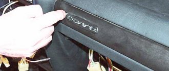
To gain access to the interior unit, where the fuses and relays of the Mazda 6 GG are located, you will need to remove the decorative cover under the dashboard.
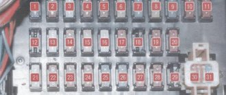
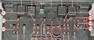
The diagram of the protective devices of the Japanese car before the restyled version includes:
- R1 – fuel supply pump;
- R2 – heating radiator fan;
- 1 – ICE ECU;
- 2, 9 – instrument panel (5A);
- 3 – heating complex of seats and rear glass;
- 4 – additional electrical circuits, heating system for exterior mirrors (7.5A);
- 5 – wipers and washer complex (20A);
- 6 – SRS, ABS;
- 7 – reversing lights (5A);
- 8 – air conditioning control program;
- 10 – fuse for the cigarette lighter Mazda 6 GG;
- 11 – lighting of luggage and interior space;
- 12 – rear wipers (10A);
- 13 – mirror position regulator (5A);
- 14 – circuit for using auxiliary devices;
- 15, 17 – electric window lifts (20, 40A);
- 16 – central locking (30A).
(link to photo source)
Most of the fuse links in the power unit of the interior space of a Japanese car have a current rating of fifteen amperes. These include devices numbered 1, 2, 3, 6, 8, 10, 11, 14.
Where are they located?
There are several fuse blocks themselves in a 2006 or 2008 Mazda car. And not for nothing, because modern foreign cars (even starting from 2002) are literally “stuffed” with modern gadgets and other types of equipment. Therefore, protecting all devices is a priority for the fuse box. The protection elements of the washer, cigarette lighter, headlight bulbs, taillight bulbs, fog lights or headlight washer all need reliable protection. Therefore, the company’s engineers decided to introduce several power supplies into the car.
Mazda 6 car
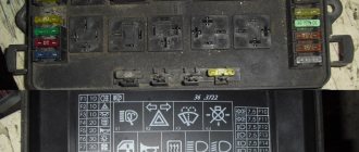
The main power supply is located inside the car, near the driver's seat. To get to it, you need to open the driver's door. In the area of the feet you will be able to see a protective plastic cover, removing which will reveal the salon mounting power supply.
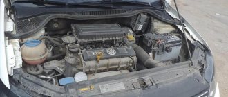
The second power supply unit, which also contains relays, is located in the engine compartment. If you open the hood and face it, you will see this power supply on the right side. In particular, it is located directly in front of the driver's seat. There is also another block with a relay, the purpose of which will be described below.
Diagram of the fuse block in the Mazda 6 GG interior after restyling
Since 2006, fuses and relays in the interior of the Mazda 6 GG are responsible for the operation of the following devices:
- R1 – fuel supply pump;
- R2 – fan of the heating complex;
- 1, 11 – socket;
- 2 – ICE ECU Mazda 6 GG;
- 3 – heating system (10A);
- 4 – mirror position regulator (5A);
- 5 – SRS, ABS (10A);
- 6 – heating complex of seats and rear glass;
- 7 – multimedia system backlight fuse (5A);
- 8 – dashboard;
- 9 – rear wipers (10A);
- 10 – central locking (30A);
- 12 – wipers and washer system (20A);
- 13 – lighting of luggage and interior space;
- 14, 15, 16 – not used.
(link to photo source)
On the restyled version of the Mazda 6 GI in the interior mounting block, the most common current rating of the fuse link is fifteen amperes.
The following are the numbers of such protective elements - 1, 2, 6, 8, 11, 13.
Reasons for fuses failure on Mazda 6
- Failure to comply with technical inspection regulations;
- Purchase and installation of non-original components
- Unprofessional installation;
- Mechanical damage to the mounting block, accident, impact, collision;
- Violation of the integrity of the insulating layer of electrical wiring;
- Short circuit in the circuit;
- Loose terminal contacts;
- Oxidation of terminals;
- Formation of condensation, moisture ingress into the mounting block;
- Manufacturing defect.
Correct replacement of fuses
familiarize yourself with the location of the protective elements of the Mazda 6 GG using the diagram on the back of the power block covers.
Directly in the blocks there are tweezers for removing damaged devices.
The process of changing fusible threads with a break involves performing the following operations:
- The cause of failure of the protective element is determined and eliminated - short circuit, poor contact or oxidation, overcurrent.
- The fuse is grabbed and pulled out from the contact part with tweezers.
- A new device is being installed. It is strictly forbidden to use fuse links with a different rated current, as well as various wires for changing. This is accompanied by the danger of damaging electrical appliances and igniting wiring. As a last resort, you can use a protective device that is responsible for the operation of non-critical electrical devices. To eliminate such situations, it is recommended to have the most popular protective elements of ten and fifteen amperes as replacements.
- The procedure for changing the relay is identical, but to remove the device, you will need to slowly loosen it and pull it out.
Recommendations for servicing the mounting block
- Periodically check the condition of the fuses, replace with new ones as necessary;
- After long trips through puddles or in the rain, check for moisture and condensation in the mounting block. Dry the board with a stream of compressed air;
- If the mechanism suddenly stops functioning, do not rush to replace it with a new one. Check the module status, use a multimeter to diagnose.
Despite the simplicity of the design of the mounting block, carry out diagnostic work at a service station. Unprofessional intervention in repairs leads to undesirable consequences.
Source: zapchasti.expert
Scheme
Especially for users of our resource, we present the diagram and purpose of the components of each Mazda device produced in 2006 and 2008.
Power supply diagram in the cabin
Under the hood
What does the device installed under the hood of the car look like and what are the links in the electrical circuit responsible for? More on this below.
A device with chain links that is located under the hood of a car.
Let's also look at the parts assignment table.
Table of purpose of parts of the device located under the hood of the car
PSU with relay under the hood
Regarding the purpose of the links:
| Part number | Purpose |
| 1 | Main fuse of the unit. |
| 6 | This relay is designed to protect the circuit of the second electric fan of the cooling system. |
| 7 | Steering wheel signal circuit protection device. |
| 8 | This component protects the circuit of the third cooling fan. |
| 9 | A device that protects the starter wiring of a machine. |
| 10 | The fourth cooling system fan. |
| 11 | Link of a dynamic low-frequency device. |
| 12 | Ensures the functionality of the mechanism designed to heat the rear window. |
| 13 | The device protects fog lamp bulbs from overvoltage. |
| 14 | Responsible for the functioning of the climate system, in particular the air conditioner. |
| 15 | The main element of this power supply. |
| 16 | This part provides protection for the headlight bulbs. |
| 17 | Responsible for the operation of the machine's dimensions. |
| 18 | The first fan of the cooling system. |
| 19 | A device that protects the headlight washer mechanism. It should be noted that in Mazda cars of 2006 and 2008 releases, the headlight washer link is weak, as it often fails. For the headlight washers, original fuses should be used to avoid frequent failure. |
| 20 | The device of the fog lamp circuit. |
| 21 | A mechanism designed to ensure the operation of the heating system fan. |
| 22 | This component is one of the most basic. He is responsible for the operation of the gasoline pump. If it fails, starting the engine will be impossible. Therefore, if you are faced with the problem of a non-working engine, you need to first check the fuel pump relay. |
Removal and replacement procedure
Changing power supply components will not cause any difficulties for Mazda owners. But how, if necessary, can you carry out the procedure for replacing the power supply yourself? We will talk about this further using the example of a salon power supply:
- First turn off the ignition and disconnect the battery from the power supply.
- Find the location of the power supply. This was stated at the beginning of the article.
- Remove the facing protective cover of the power supply unit.
- Disconnect the blocks with harnesses leading to the power supply. Using a screwdriver, unscrew the screw that secures it. Press the latch and remove the device.
- Replace the power supply with a new one, and install it in the reverse order.
1. Remove the protective trim from the interior
2. Following the steps, remove the power supply and replace it with a new one
