Audi 80 b4 cars manufactured in 1991, 1992, 1993, 1994, 1995 were considered.
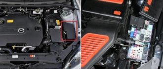
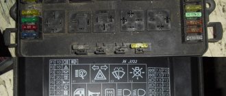
Fuse box in the engine compartment.
The unit is located in the rear left side of the engine compartment.
Explanation:
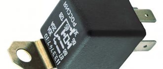
- relay
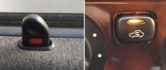
- diagnostic connector
- fuses 1-21. Cars with diesel engines have 22 fuses.
- additional fuses 23-32
- four spare fuses
- relay designation on the distribution panel cover
- clamp for removing and installing fuses
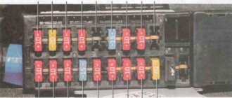
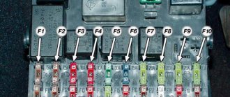
Layout of fuses and relays in the block.
Explanation:
| № | Purpose | Ampere |
| 1 | Fog lights, rear fog lights | 15 |
| 2 | Alarm | 15 |
| 3 | Horn, heated seats | 30 |
| 4 | Electronic clock, trunk light, interior light, vanity mirror, reading light, cigarette lighter, on-board computer, automatic air conditioning, radio, self-diagnosis system | 15 |
| 5 | Radiator fan rotation speed 2 | 30 |
| 6 | Rear right side and parking lights | 5 |
| 7 | Rear left side and parking lights | 5 |
| 8 | Right high beam headlight, high beam warning light | 10 |
| 9 | Left high beam headlight | 10 |
| 10 | Right low beam headlight, right headlight leveling motor | 10 |
| 11 | Left low beam headlight, left headlight leveling motor | 10 |
| 12 | Instrument panel, reversing lights, control system, automatic transmission, differential lock, on-board computer, speed control, retarder relay, interior lighting, electronic thermal switch, radiator fan relay | 15 |
| 13 | Fuel pump | 15 |
| 14 | License plate light, instrument panel light, engine compartment light, glove box light, automatic air conditioning | 5 |
| 15 | Turn signals, windshield wiper, windshield washer pump, heated windshield washer jets, radiator fan relay, air conditioning | 25 |
| 16 | Heated rear window, heated mirrors | 30 |
| 17 | Interior blower fan, automatic air conditioning | 30 |
| 18 | Electric mirrors | 5 |
| 18 | Rear window wiper (Avant) | 15 |
| 19 | Central locking, heated lock switch cylinder, anti-theft system | 10 |
| 20 | Radiator fan, 1st speed, interior fan | 30 |
| 21 | Diagnostic connector | 10 |
| 22 | Not used (vehicles with gasoline engines) | |
| 22 | Glow plugs (vehicles with diesel engines) | 80 |
Additional fuses, bottom row:
| 23 | Not used | — |
| 24 | Not used | — |
| 25 | Lambda probe heating. Not used for vehicles with diesel engines | 5 |
| 26 | Trailer connector | 30 |
| 27 | Ignition/fuel injection system | 10 |
| 28 | Ignition/fuel injection system. Not used for vehicles with diesel engines | 10 |
| 29 | Stop signal | 10 |
| 30 | Speed control (vehicles with automatic transmission) Not used for vehicles with diesel engines. | 5 |
| 31 | ABS, differential lock | 15 |
| 32 | Ignition/fuel injection system Vehicles with TD diesel engines have a fuel shut-off valve | 10 |
Relay decoding:
1 - relay for fog lights and rear parking lights. For cars without fog lights, there is a jumper in this place.
2 - radiator blower fan relay (for cars without air conditioning), radiator blower fan relay for turning on the 2nd stage of rotation
3 - fan relay
4 - headlight washer relay
5 — X-contact of unloading relay
6 - relay for interior blowing fans (manually controlled air conditioning), air conditioning fan relay for speed at the 2nd stage (automatically controlled air conditioning)
7 - horn relay
8 - sound alarm relay for anti-theft system (vehicles with manual transmission). Cars without such a system have a jumper. For cars with automatic transmission this space is free.
9 — window wiper interval relay
10 - fuel pump relay
11 - radiator fan relay for turning on the 1st stage of rotation
* Attention! For vehicles with diesel engines, pos. 2 and 3 are not occupied and relay 10 is the glow plug relay
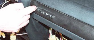
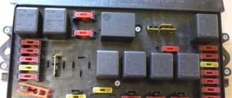
Additional relay block in the interior of the Audi 80 b4.
To access the unit, unscrew the 4 screws and remove the cover.
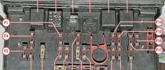
Relay location diagram in the block.
Not all relays are installed on different modifications of cars.
Explanation:
- ABS system
- Seat belt warning light
- Interior lighting control unit
- Air conditioner clutch relay block
- Rear window wiper and washer system
- Oil pressure monitor, front lighting control unit
- Not used
- Not used
- Automatic shift lock (automatic vehicles only)
- Not used
- Not used
- Heated passenger seats
- Heated driver's seat
- Car sunroof relay
- Electric sunroof and door window control unit
- Electric sunroof and door window control unit
- Anti-theft warning lamp relay
- Power Windows, Power Sunroof, Power Seat Circuit Breaker
Purpose of the relay for diesel engines.
Explanation:
5 - electric current relay
12 - acoustic signal relay (door not closed, seat belt not fastened)
13.14 - exhaust gas recirculation control relay
15 - lighting lamp control relay
18 - relay for the 3rd speed of rotation of the radiator fans (usually this is the 2nd speed)
K - radiator fan fuse
S - electric current fuse
Description of fuses
To see the fuses of the Audi 80, you should open the hood - the block is located on the back left side. It consists of:
- relay
- diagnostic connector;
- main - 21 pieces (diesel versions have 22), additional and spare (4 pieces) fuse blocks;
- distribution panel covers with relay circuit;
- clamp for removing and installing fuses.
The additional unit is located in the Audi 80 interior; to get to it you will need to unscrew four screws and remove the cover.
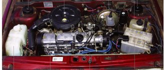
Mounting block in the engine compartment
If the fuel pump stops working, the first thing you should do is check its fuse. To do this, you need to open the hood of the Audi 80 b3 and look into the niche near the windshield on the driver's side. In this place there is an Audi 80 fuse box, a relay and a diagnostic connector for connecting the car to the computer.
Useful article: Audi 80 mono-injection will not start: troubleshooting options
For Audi 80 to 91, the fuel pump fuse is number 13 in the top row, its rating is 15 amperes. In total, the block contains 21 elements (models with a diesel engine have 22), and the wiring diagram also contains additional fuses used depending on the modification and configuration of the car.
Additionally, the mounting block contains the following relays:
- fuel pump relay;
- relay for fog lights and tail lights (if not included in the package, then a jumper is installed in this place);
- starter relay;
- horn relay;
- turns relay;
- climate control relay;
- wiper relay;
- relay for headlight washer, fan, security system, etc.
On the cover of the mounting block there is a diagram of the elements; there is also a decoding in the operating manual for the Audi 80 b3.
For the Audi 80 B4 brand, the location of the mounting block is completely similar, with the exception of the total number of elements and their purpose. So, the fuel pump in b4 is connected to element No. 12, and the location of the relay is also different from model b3.
If a malfunction occurs with electrical equipment, you should first check the integrity of the fuses located in the engine compartment of the car. Even if the speedometer has stopped working, then with a good degree of probability the reason may be hidden in the fuses; it is much easier to notice their integrity than to disassemble the instrument panel and directly check its elements for malfunction.
Experienced drivers use the fuse responsible for the operation of the fuel pump as follows: often in winter, unsuccessful attempts to start the engine lead to the spark plugs being “flooded” with gasoline, as a result of which the car cannot be started. To dry the spark plugs, just remove the pump fuse from the block and turn the engine with the starter for a few seconds - the fuel supply will stop, and due to ventilation they will dry out quite quickly.
Main fuse and relay box
The main unit includes twenty-one (for diesel models 22) devices, which is clear from the tables. They are universal for all Audi 80 models, but depending on the configuration, the location may differ. Before making repairs, check the location of the fuses on the back of the unit's protective cover.
| Number | Current in amperes | What is he responsible for? |
| 1 | 15 | Operation of fog lights |
| 2 | 15 | Emergency Signal |
| 3 | 30 | Heated seats |
| 4 | 15 | Electronic clock operation, interior and trunk light, cosmetic mirror, reading light, cigarette lighter, computer, air conditioning, radio, self-diagnostic system operation |
| 5 | 30 | 2nd rotation mode of the fan cooling the radiator |
| 6 | 5 | Tail lights and parking lights, right |
| 7 | 5 | Tail lights and parking lights, left |
| 8 | 10 | High beam, headlight and warning light operation |
| 9 | 10 | High beam, left lamp |
| 10 | 10 | Low beam - right headlight and its movement mechanism |
| 11 | 10 | Low beam - left headlight and its movement mechanism |
| 12 | 15 | Instrument panel, reversing light, control system, automatic transmission, differential lock, on-board computer, speed mode, operation of the retarding relay, electronic thermal switch and radiator cooling fan switch-off relay |
| 13 | 15 | Fuel pump operation |
| 14 | 5 | Illumination of license plates and dashboard, light (under the hood and in the glove box, air conditioning |
| 15 | 25 | Turn signals, windshield wiper, windshield washer pump, heated windshield washer jets, radiator fan relay, air conditioning |
| 16 | 30 | Heated mirrors and rear window |
| 17 | 30 | Interior fan, air conditioning |
| 18 | 5/15 | Operation of electric mirrors/wiper on rear window (Avant) |
| 19 | 10 | Central locking, heating mechanism, anti-theft system operation |
| 20 | 30 | Radiator blowing, first mode |
| 21 | 10 | Diagnostic socket |
| 22 | 80 | Glow plugs (for diesel versions only) |
Read also Removing and replacing the contact group of the ignition switch Audi 80
Purpose
Now let's move on to the purpose of the power supply components. The tables are presented below.
Regarding relays, this information will probably also be useful to you.
| Serial number | What protects |
| 1 | Ensures the safe operation of fog lamps and tail lights, as well as the bridge, if the vehicle is not equipped with fog lamps. |
| 2 | This part protects the cooling system fan from failure (relevant for vehicles not equipped with a climate control system). |
| 3 | Provides the functionality of the ventilated device activation control unit after the motor is turned off. |
| 4 | This device allows the headlight washer system to function safely. |
| 5 | X-contact relief component. |
| 6 | For vehicles with manual air conditioning, this component performs the function of protecting the fan circuit, and on cars with an automatic climate control system and some other engine variations, the sixth number designates the relay responsible for the operation of the second cooling system fan. |
| 7 | Responsible for the functionality of the steering horn. |
| 8 | This number allows you to ensure the functionality of the alarm system in Audi 80 cars equipped with a manual transmission. If your vehicle is equipped with an automatic transmission, this location will remain open. |
| 9 | Windshield wash intermittent component. |
| 10 | Gasoline pump Audi 80. |
| 11 | The first fan of the cooling system. |
Each electrical device in a car is designed for a specific voltage. The diameter of the supply wire is calculated taking into account this voltage. If the current consumption in a certain circuit, for example, due to the connection of additional consumers, increases, then the supply wire experiences additional load. It may overheat or even burn out if the flow of current is not interrupted in a timely manner. This function is performed by fuses. To avoid complete blackout of the on-board network, each circuit has its own fuse. However, connections to the battery, alternator, starter and ignition switch do not have fuses.
To remove and replace fuses, use the plastic clip that is attached to the cover of the central distribution panel (see illustration 3.0).
If a new fuse blows immediately after installation, make sure that the fuse of the required rating was installed, and not a smaller one. If the rating corresponds, then check individually all consumers of this circuit. Use the appropriate electrical diagram for this. If necessary, disconnect all consumers in the circuit and then connect one at a time. If, when connecting the next consumer, the fuse blows, then this consumer is faulty.
Additional block
| Number | Current in amperes | What is he responsible for? |
| 25 | 5 | Operation of the lambda probe heating system (only for gasoline versions) |
| 26 | 30 | Trailer mechanism |
| 27 | 10 | Fuel injection/ignition |
| 28 | 10 | Ignition/injection (only for gasoline-free versions) |
| 29 | 10 | Feet |
| 30 | 5 | Adjusting the speed mode (only for gasoline versions with automatic transmission) |
| 31 | 15 | ABS differential lock mechanism |
| 32 | 10 | Fuel shut-off valve (diesel versions) |
Attention! It should be remembered that fuses 23 and 24 are not used on the Audi 80.
14.2.1.4. Identifying Contacts on the Fuse and Relay Box Boards
Chevrolet Niva fuses and relays
Identification of relay blocks (Audi-80/90)
| 1. Fog lights J5 2. Radiator cooling fan (stage 2) J101 3. Engine-off radiator cooling fan control unit J138 4. Not used 5. Load reduction relay J18 | 6. A/C fresh air blower J11 7. Horn J4 8. Jumper between pins 36 and 38 of manual transmission 9. Automatic transmission J60 10. Fuel pump J17 11. Radiator cooling fan (stage 1) J26 |
Identifying Contacts on the Fuse and Relay Box Boards
| RELAY BOX LOCATION | CONTACT NUMBER | NUMBER ON RELAY BOX | USAGE |
| 1 | 10 | 86 | Fog lamps |
| 11 | 30 | ||
| 12 | 85 | ||
| 13 | 87 | ||
| 2 | 14 | 30 | Radiator Cooling Fan High Speed Relay |
| 15 | 85 | ||
| 16 | 87a | ||
| 17 | 87 | ||
| 18 | 86 | ||
| 3 | 1 | 15 | Radiator cooling fan control unit when the engine is off |
| 2 | 30 | ||
| 3 | 31 | ||
| 4 | |||
| 5 | ST1 | ||
| 6 | |||
| 7 | 87 | ||
| 8 | |||
| 9 | |||
| 4 | Open | ||
| 5 | 24 | 30 | Load reduction relay |
| 25 | 85 | ||
| 26 | 87 | ||
| 27 | 86 | ||
| 6 | 58 | Air conditioner relay | |
| 28 | 86 | ||
| 29 | 87a | ||
| 30 | 30 | ||
| 31 | 85 | ||
| 7 | 32 | 87 | Sound signal device |
| 33 | 86 | ||
| 34 | 30 | ||
| 35 | 65 | ||
| 8 | 36 | 87 | Automatic transmission |
| 37 | 86 | ||
| 38 | 30 | ||
| 39 | 85 | ||
| 9 | 40 | 53e | Windshield washer and wiper switch |
| 41 | 53c | ||
| 42 | 31b | ||
| 43 | 15 | ||
| 44 | 31 | ||
| 45 | I | ||
| 10 | 46 | 15 | Fuel pump |
| 47 | T | ||
| 46 | 30 | ||
| 49 | L | ||
| 50 | 31 | ||
| 51 | 1 | ||
| 52 | 87 | ||
| 53 | |||
| 59 | |||
| 11 | 54 | 87 | Radiator Cooling Fan Low Speed Relay |
| 55 | 86 | ||
| 56 | 30 | ||
| 57 | 85 |
Identification of relay blocks (Audi-80/90, 80/90 Quattro and Coupe, starting from models 1989)
| 1. Fog lamps, J5 2. Not used 3. Engine off radiator cooling fan control unit, J138 4. Headlight washer system, J39 5. Load reduction relay, J18 6. Radiator cooling fan high speed relay, J101 | 7. Horn, J4 8. Jumper between manual transmission pins 36 and 38 8. Automatic transmission, J60 9. Windshield washer/wiper switch, J31 10. Fuel pump, J17 11. Radiator cooling fan low speed relay, J26 |
Identifying Contacts on the Fuse and Relay Box Boards
| RELAY BOX LOCATION | CONTACT NUMBER | NUMBER ON RELAY BOX | USAGE |
| 1 | 10 | 86 | Fog lamps |
| 11 | 30 | ||
| 12 | 85 | ||
| 13 | 87 | ||
| 2 | Open | ||
| 3 | 1 | 15 | Radiator cooling fan control unit when the engine is off |
| 2 | 30 | ||
| 3 | 31 | ||
| 4 | T | ||
| 5 | ST1 | ||
| 6 | |||
| 7 | 87 | ||
| 8 | |||
| 9 | |||
| 4 | 19 | 30 | Headlight washer system |
| 20 | 85 | ||
| 21 | 86 | ||
| 22 | 87 | ||
| 23 | |||
| 5 | 24 | 30 | Load reduction relay |
| 25 | 85 | ||
| 26 | 87 | ||
| 27 | 86 | ||
| 6 | 58 | 87 | Radiator Cooling Fan High Speed Relay |
| 28 | 86 | ||
| 29 | 87a | ||
| 30 | 30 | ||
| 31 | 85 | ||
| 7 | 32 | 87 | Sound signal device |
| 33 | 86 | ||
| 34 | 30 | ||
| 35 | 85 | ||
| 8 | 36 | 87 | Automatic Transmission Jumper (Manual Transmission) |
| 37 | 86 | ||
| 38 | 30 | ||
| 39 | 85 | ||
| 9 | 40 | 53e | Windshield washer and wiper switch |
| 41 | 53c | ||
| 42 | 31b | ||
| 43 | 15 | ||
| 44 | 31 | ||
| 45 | I | ||
| 10 | 46 | 15 | Fuel pump |
| 47 | T | ||
| 46 | 30 | ||
| 49 | L | ||
| 50 | 31 | ||
| 51 | 1 | ||
| 52 | 87 | ||
| 53 | |||
| 59 | |||
| 11 | 54 | 87 | Radiator Cooling Fan Low Speed Relay |
| 55 | 86 | ||
| 56 | 30 | ||
| 57 | 85 |
Fuse and relay block board, contacts for wiring connections
| A – Contacts for connecting the plug of the air conditioning system, color gray B – Contacts for connecting the plug of the front right wiring harness, color black C – Contacts for connecting the plug of the instrument cluster, color blue D – Contacts for connecting the plug of the front left wiring harness, color green E – Contacts for connecting the plug of the front left wiring harness, color yellow F – Contacts for connecting the plug of the instrument cluster, color brown G – Contacts for connecting the plug of the instrument cluster, color red | H – Contacts for connecting the plug of the rear wiring harness, color black I – Contacts for connecting the plug of the instrument cluster, color red J – Contacts for connecting the plug of the instrument cluster, color yellow K – Contacts for connecting the plug of relay 3, color black L – Contacts for connecting single plug (terminal 30), color clear M – Contacts for connecting a plug of non-standard equipment installed on request, color clear N – Not used O – Not used P – To fuse 20 |
| previous page14.2.1.3. Fuse locations and identification | next page 14.2.1.5. Additional relay block board |
Signs of faulty fuses on the Audi 80 B3 of the first – third generations
The corresponding indicator on the dashboard indicates that one or more fuses need to be replaced. A number of signs also indicate this:
- A noticeable chemical smell from the instrument compartment (as if burning plastic);
- When you turn the ignition key or shift the transmission lever, some devices do not work;
- A spark shoots through the mounting block.
If at least one of these signs appears, you should immediately take the car to a workshop.
Causes of fuse failure
Most often, breakdowns occur for the following reasons:
- Negligent attitude to the schedule of scheduled technical inspection;
- Poor quality repairs (defects, repairs by self-taught or insufficiently qualified auto mechanics);
- Wear, mechanical damage;
- Damage to the insulation of the car electrical wiring;
- Short circuits;
- Oxidation and condensation on the boards;
- Terminal contacts are loose.
Fuses never fail by accident; this usually results from a whole chain of disturbances in the operation of the electrical system. Also, the greed of car owners and the desire to save on original spare parts and repairs are largely to blame for this - it is rare to find analogues that are not inferior in quality to the original.
Important: under no circumstances should you install a piece of foil or wire instead of a fuse - this can lead to a fire!
Replacing fuses on Audi 80 B3
The procedure for replacing a fuse on an Audi 80 B3 is not complicated and consists of the following steps:
- The engine is turned off, the hood is raised, the car itself is de-energized - to do this, remove the negative terminal from the battery.
- Unscrew the screws from the fuse box cover and remove it. Before replacing, you should look at the back of the cover - there is a location diagram there.
- Using tweezers or pliers, remove the burnt fuse and replace it with an analogue with exactly the same indicator.
All that remains is to connect the current and check if all devices are working.
Electrical diagram
Fuses and relays lada 2121
Electrical diagrams of a car are graphic images that display the main electrical elements. Such maps do not show the actual location of certain parts, but they do show the relationship between the components.
. This skill can help in case of car breakdowns. If the car owner knows how to read electrical diagrams, then he will be able to independently identify the breakdown. This means that you will not need to undergo diagnostics (which cost a lot) at a car service center. In this article we will analyze the electrical circuit of the Audi 80.
For those who are not yet very versed in circuits, let’s specifically look at some of the nuances:
- All connections (or combinations of connections) of wires on the Audi 80 b3 wiring diagram are marked in different colors. Each of them is responsible for a separate part of the circuit;
- The wires in the circuits are connected to each other using several methods. One of them is connectors. In this case, the letter “C” is written next to the connection, and after it there is a number corresponding to the serial number of the connection;
- The wires can also be connected using connecting blocks or jumpers. Then opposite the connection there is already the letter “S” (and the serial number itself).
He, in turn, determines the denomination. Below we have presented a table in which the fuse rating corresponds to its color on the Audi 80 B3 electrical diagram.
| Fuse rating | Indicating color on the diagram |
| 100A | Lilac (light purple) |
| 80A | Light yellow |
| 70A | Dark brown |
| 60A | Blue |
| 40A | Orange |
| 30A | Green |
| 25A | White |
| 20A | Yellow |
| 15A | Blue |
| 10A | Red |
| 7.5A | Brown |
| 5A | Dark yellow |
| 3A | Violet |
| 2A | Grey |
| 1A | Black |
Fuse Maintenance Recommendations
Even trouble-free equipment will sooner or later require repairs. However, there is a way to extend the life of fuses on an Audi. To do this, you should follow simple rules:
- Do not skimp on spare parts and buy originals whenever possible;
- After a trip in wet weather, check the mounting block and dry it if necessary;
- Install modules only within the recommended current limits;
- Get diagnosed in a timely manner.
Read also Review of the Audi model range: list of new products for 2020
On average, the operation of Audi 80 (B3) batteries and relays is approximately fifty thousand kilometers. They rarely fail on their own; as a rule, this is due to the illiterate actions of car owners.
Additional Information
Check out this video. Here you can clearly see how to access the fuse panel in the B3 model.
If you want to know more, download a free book on repair and operation of the Audi 80 b3: ""
In order for your “iron horse” to always work properly, you need to periodically devote time to diagnosing it. This includes the electrical wiring of the vehicle. This material will help you find out where the Audi 80 fuses are located, what they are responsible for and how to change them if necessary.