07/18/2021 79 952 110 Sensors
Author: Ivan Baranov
The main signs of a malfunction of the mass air flow sensor are loss of engine power, difficult starting, “floating” engine speed. To find out the exact cause of the flow meter failure, you need to visually inspect the device and then test it with a scanner (via Openidag), a voltmeter or a motor tester.
[Hide]
Sensor repair
Any electronic device has a huge disadvantage: sensitivity to the slightest power surges, pollution, aggressive environmental influences and many other factors.
If even a tiny particle of dirt or dust gets into the air flow entering the engine, it will certainly settle on the sensor, which, being so vulnerable, attracts such troubles to itself like a magnet. Continuing to work in this state, he is forced to increase the load, as dust ballast interferes with him. Consequently, it starts to fail. Also, if low-quality oil or bad gasoline is poured into the engine, all this first of all has a very negative impact on the electronic device
This is why it is so important to pay attention to air, oil and other filters and not skimp on the quality of fuels and lubricants poured into the engine.
Having made sure that the VAZ mass air flow sensor is faulty, we move on to the next stage - repair. Repair consists of a good cleaning. But how is the mass air flow sensor cleaned and is it possible to do this work with your own hands? To begin with, you should remember, like a multiplication table, that in no case should you use the following for flushing:
For cleaning, use carburetor cleaning fluid. The most popular in this matter is WD 40, which has good technical properties and is safe for electronic devices. You need to wash the sensor carefully so as not to damage the thinnest plates and wiring.
After making sure that there is no more dust or debris in the device, you can, after thoroughly drying it, install it in place. As a rule, after such a simple procedure, the device should work like a good Swiss watch. We have discussed the most frequently asked questions regarding the mass air flow sensor. Now you know why it breaks, what needs to be done to protect it, and what to do if it suddenly malfunctions. We wish you good luck on the roads and good mood!
Recommendations for increasing service life
DMRV for a gazelle car
To extend the life of the MAF sensor, follow these recommendations:
- Change the air filter promptly to minimize clogging of the flow meter.
- Monitor the technical condition of the engine, carry out maintenance on time, change and fill only with high-quality engine oil.
- If the car has a high mileage, check the engine compression - wear or jamming of the piston rings and valve seals will lead to oil penetration into the intake system. This will prevent the appearance of oil deposits on the thermistors.
- Monitor the condition of the crankcase ventilation system. This is especially true for those engines where the crankcase gas suction pipe is connected in front of the mass air flow sensor. Check the condition of the oil separator under the valve cover.
Purchasing a new and replacing the mass air flow sensor
DMRV sensor
Purchasing and replacing a mass air flow sensor is not a problem. The market is teeming with offers. Prices also vary from 2500 to 9000 rubles. For VAZ and GAZ, look for Bosch products with article number 0280218037.
To replace you will need:
- Cross-shaped or flat decoction.
- Key head 10 (for Lada Kalina).
Procedure:
- Loosen the air duct clamp bolt and move the latter to the side.
- Press the button under the plug and pull the latter out of the connector.
- Using a 10mm wrench, unscrew the two bolts (one on top, the other on bottom).
- Remove the sensor.
- Installation in reverse order.
Before buying a new flow meter, pay attention to the markings of the old one. It is advisable to purchase a product with the same marking so that it is guaranteed to be compatible with the car’s ECU
The main thing after replacement is not to forget to adapt the new flow meter. To do this, remove the negative terminal of the battery for a few minutes to expose the data in the ECU.
In some car models, this cannot be done in a garage; you will have to go to a service center where there is special diagnostic equipment.
Self-diagnosis procedure for Chevrolet Niva via OBD2 connector
Determine where the OBD2 connector is located
- From 1990-1994 they are equipped with an OBD1 (GM12) connector - 12 PIN.
- Since 1995, cars have been produced with an OBD2 connector - 16 PIN.
The location of the connector also depends on the type of connector. You can study this issue in the article: “Location of the diagnostic connector on the Chevrolet Niva”
Determine which scanner is suitable for your car
The selection of a scanner (adapter) for a Chevrolet Niva depends on the connector, as well as on the needs of the diagnostician / car owner.
To select diagnostic equipment, use the calculator: “Scanner selection for Chevrolet Niva”
Download the diagnostic program for the scanner
The diagnostic adapter requires software that can be installed on a laptop or smartphone/tablet. Auto scanners with their own software shell and display do not require software.
To select a program for the adapter, go to the section: “Programs”
Use the instructions and carry out diagnostics
When you purchase an adapter, instructions are included with the adapter. More detailed instructions on diagnostic scanners and descriptions of their operation are posted in the section: “OBD2 car scanner reviews”
Identify errors and decipher them
Error codes and their interpretation are displayed in the scanner program interface. You can also study the complete database of errors for your car in the section: “OBD2 error codes for Niva Chevrolet”
Make repairs according to the error code
The unit is repaired according to the decoding of the error (problem) or contact a car service to eliminate a particular malfunction.
Check errors again
Scan Tool Pro - budget multiscanner for Chevrolet Niva
A good choice for a novice diagnostician
Nowadays there are scanner models with different versions of firmware and chips on sale. Scan Tool Pro with firmware 2021 is the most stable version so far, and also has maximum compatibility with cars manufactured since 2001, including the Chevrolet Niva.
By following the link on the right you can get acquainted with the scanner for autodiagnostics “Scan Tool Pro”. This is an official dealer website that provides a 12 month warranty.
Cleaning the air flow sensor
How to clean the DMRV on a VAZ 2114: all the subtleties of the process
As noted earlier, the mass air flow sensor cannot be repaired. But some craftsmen manage to clean it, thus extending the service life of the monitoring device in question. Moreover, some claim that they have done this more than once.
In reality, it is worth recognizing that the chance of repair is quite low. However, if you take into account that the cost of a new sensor is quite high, and an attempt to revive the old one generally requires nothing but time, then you should try.
To clean the air flow sensor you will need:
- composition for cleaning carburetors;
- soft brush;
- Phillips screwdriver.
The sensor is disassembled and the inside of the tube and the platinum wire itself are carefully cleaned. Next, all parts must be left to dry. During this time, remove the throttle entirely and also clean it of any plaque inside. Do not remove the cable from the gas pedal. The assembly is placed on a clean rag and washed with carburetor fluid. You will also need to clean the idle speed regulator and the surrounding area from dirt. If you managed not to damage the wire in the mass air flow sensor, then eventually the problem will become less acute for some time
It is important that the sensor is not damaged mechanically
Finally, it is worth noting that to increase the service life of the sensor, first of all, it is necessary to replace the air filter on time.
Replacing the mass air flow sensor
Removing the mass air flow sensor
If the check indicates a malfunction of this sensor, it is replaced, since they are irreparable. Replacing it is very simple. Using an example, we will look at replacing a sensor on a VAZ-2110.
All replacement work is carried out with the ignition off. First, the chip with the wires going to the sensor is disconnected from the sensor.
Then you need to loosen the clamp securing the inlet pipe to the filter, after which the pipe is disconnected from the filter.
Using a 10mm wrench, unscrew the two bolts that secure the sensor. The sensor can now be removed from its seat.
Here you can learn how to remove the crankshaft pulley.
In this article you can learn how to replace the cabin filter in a car.
Before installing a new sensor in a seat, it is important to check the tightness of the sealing ring, otherwise, if the density is insufficient, there is a possibility of air leaking in, not cleared of impurities, from the outside. And this can cause rapid damage to the sensor.
After checking the seal, the sensor is put in place and secured with bolts. Next, put the pipe in place and connect the chip with wires.
The final stage is to check the restoration of normal operation of the power plant.
TEST SEQUENCE
HINT: Use a handheld diagnostic tool to read the fixed parameters. These parameters reflect the state of the engine at the time the malfunction was detected. When troubleshooting, fixed parameters allow you to determine whether the car was moving at the time of the malfunction or not, whether the engine was warmed up, what the air-fuel mixture was (lean or rich), etc.
| 1.TAKE HAND-HELD TEST READINGS (MASS AIRFLOW) |
Connect the handheld diagnostic tool to the DLC3.
Start the engine and turn on the handheld scan tool.
Select the following menu items: Powertrain / Engine and ECT / Data List / MAF.
Read the values displayed on the scan tool.
Result:
| Air mass flow (g/s) | Next step |
| 0,0 | A |
| Not less than 271.0 | B |
| Between 1.0 and 270.0 (*1) | C |
*1: The value should change when the throttle valve is opened or closed while the engine is running.
| B |
Go to step 6 C
CHECK FOR INTERMITTENT PROBLEMS
| A |
| 2.CHECK MASS AIRFLOW SENSOR (SUPPLY VOLTAGE) |
Disconnect the mass air flow (MAF) sensor connector B1.
Turn on the ignition (IG).
Measure the voltage between the harness-side connector pin and ground.
Rated voltage:
| Contacts for connecting a diagnostic tool | Specified conditions |
| +B (B1-3) - mass | 9-14 V |
Reconnect the mass air flow sensor connector.
| NG |
Go to step 5
| OK |
| 3.CHECK MASS AIRFLOW SENSOR (VG TERMINAL VOLTAGE) |
Check the output voltage.
Disconnect connector B1 of the MAF sensor.
Apply battery voltage to terminals +B and E2G.
Connect the scan tool positive (+) probe to terminal VG and the scan tool negative (-) probe to terminal E2G.
Rated voltage:
| Contacts for connecting a diagnostic tool | Specified conditions |
| VG (5) - E2G (4) | 0.2-4.9 V |
Reconnect the mass air flow sensor connector.
| NG |
REPLACE MASS AIRFLOW SENSOR
| OK |
| 4.CHECK HARNESS AND CONNECTOR (MASS AIRFLOW SENSOR - ECM) |
Disconnect connector B1 of the MAF sensor.
Disconnect ECM connector B32.
Nominal resistance (check for open):
| Contacts for connecting a diagnostic tool | Specified conditions |
| VG (B1-5) - VG (B32-118) | Less than 1 ohm |
| E2G (B1-4) - E2G (B32-116) |
Nominal resistance (check for short circuit):
| Contacts for connecting a diagnostic tool | Specified conditions |
| VG (B1-5) or VG (B32-118) – weight | 10 kOhm or more |
Reconnect the mass air flow sensor connector.
Connect the ECM connector.
| NG |
REPAIR OR REPLACE HARNESS OR CONNECTOR
| OK |
| REPLACE ECM |
| 5.CHECK HARNESS AND CONNECTOR (MASS AIRFLOW SENSOR - INTEGRATED RELAY) |
Disconnect connector B1 of the MAF sensor.
Remove the integrated relay from the No. 1 relay block in the engine compartment.
Nominal resistance (check for open):
| Contacts for connecting a diagnostic tool | Specified conditions |
| +B (B1-3) - 1A-4 | Less than 1 ohm |
Nominal resistance (check for short circuit):
| Contacts for connecting a diagnostic tool | Specified conditions |
| +B (B1-3) or 1A-4 - mass | 10 kOhm or more |
Reconnect the mass air flow sensor connector.
Reinstall the integrated relay.
| NG |
REPAIR OR REPLACE HARNESS OR CONNECTOR
| OK |
| CHECK ECM POWER CIRCUIT |
| 6.CHECK HARNESS AND CONNECTOR (SENSOR GROUND) |
Disconnect connector B1 of the MAF sensor.
Nominal resistance:
| Contacts for connecting a diagnostic tool | Specified conditions |
| E2G (B1-4) - mass | Less than 1 ohm |
Reconnect the mass air flow sensor connector.
| OK |
REPLACE MASS AIRFLOW SENSOR
| NG |
| 7.CHECK HARNESS AND CONNECTOR (MASS AIRFLOW SENSOR - ECM) |
Disconnect connector B1 of the MAF sensor.
Disconnect ECM connector B32.
Nominal resistance (check for open):
| Contacts for connecting a diagnostic tool | Specified conditions |
| VG (B1-5) - VG (B32-118) | Less than 1 ohm |
| E2G (B1-4) - E2G (B32-116) |
Nominal resistance (check for short circuit):
| Contacts for connecting a diagnostic tool | Specified conditions |
| VG (B1-5) or VG (B32-118) – weight | 10 kOhm or more |
Reconnect the mass air flow sensor connector.
How to check the mass air flow sensor
The most reliable method of checking the mass air flow sensor is to “throw in” a known-good sensor. It is better to take it from the owner of a similar car.
It contains very thin threads (plates) that are easily damaged. It is not recommended to take a used sensor for disassembly; with a high degree of probability it may not work. A malfunction of the sensor can cause even slight contamination or coating with an oil coating.
The second method is to disconnect the connector from the mass air flow sensor. If the car starts and the engine runs smoothly and picks up speed smoothly, this is evidence of a possible sensor malfunction.
Checking the mass air flow sensor with a multimeter
You can check the serviceability of the threads (plates) using a multimeter. To do this, you need to know the sensor circuit and pinout. For example, in VAZ cars it is necessary to connect the multimeter probes (with the connector turned on) between the green and yellow wires of the connector.
This can be done using sewing needles, pins, piercing the insulation or inserting them into the connector on the other side. A voltage from 1.0 to 1.1 Volts will indicate that the sensor is working, more than 1.2 Volts - the sensor must be replaced.
Video - checking the mass air flow sensor with a multimeter:
Some mass air flow sensors can be checked visually. They have two threads (plates). If you remove the sensor, you can visually assess their integrity and the absence of contamination.
There are more complex control methods using a hair dryer to simulate the movement of air flows, an oscilloscope, but they are not as effective.
Broken sensor threads, lack of voltages and currents of the mass flow sensor are determined by diagnostic devices. In cars produced after 2005, OBD engine diagnostics provides information on the mass consumption of the fuel mixture, which can also be used to judge the performance of the mass air flow sensor.
DMRV of VAZ 2115 car
VAZ 2115 cars are the last link in the Samara family and inherited the range of engines from it. Accordingly, the engine ECU controllers and the mass air flow sensors combined with them are similar. Flow meter compatibility is determined by the ECU type, and is as follows:
- ICE VAZ 2111 - Mass air flow sensor 0 280 218 004 (obsolete) or 0 280 218 037, environmental standard Euro 2;
- ICE VAZ 21114 - MAF 0 280 218 116, environmental standard Euro 2;
- ICE VAZ 211183 - Mass air flow sensor 0 280 218 116, environmental standard Euro 3.
Actually, ecology is not related to the type of flow meter; exhaust toxicity is set by the settings of the ECU controller.
- Yellow (closest to the windshield) - mass air flow sensor signal input;
- Gray-white—sensor supply voltage output;
- Green — sensor grounding output;
- Pink-black - to the main relay.
The wire colors may change, but the pin locations remain the same.
Let’s also add that the mass air flow sensor with endings 004, 037, 116 (for Bosch) and 00, 10, 20 (for Pekar) are different in calibration. You can only change it by flashing it.
Main symptoms of a malfunctioning mass air flow sensor
A malfunction of the mass air flow sensor, as noted above, leads to either an over-enrichment or a depletion of the fuel mixture with gasoline or diesel fuel, which negatively affects the functioning of the engine and can lead to serious damage. Most often, malfunctions of the mass air flow sensor are associated with a clogged air filter: the air is poorly cleaned, and the mechanical particles contained in it get into the sensor, which is the cause of its failure. It should be noted that mass air flow sensors are non-repairable devices, and if they fail, they must be replaced with new ones.
Practice shows that the main signs of a malfunction of the mass air flow sensor are as follows:
- A Check Engine error appears, which indicates that the signal level of this sensor is very low;
- The engine consumes more fuel than usual;
- The power unit does not start well, its power decreases, it begins to stall;
- The car accelerates poorly;
- The engine runs either at high or low speed.
Of course, all the signs may also appear during other vehicle malfunctions, but in any case, if at least one of them is detected, this is a good reason to visit a service station. However, you can check the mass air flow sensor for malfunctions yourself, without contacting service station specialists.
PURPOSE AND PRINCIPLE OF OPERATION
The VAZ 2114 injection engine is a complex design capable of operating in different load modes. In order to ensure normal operation of the power unit and the optimal amount of gasoline consumed, the car’s electronic brains must determine as accurately as possible the ratio of gasoline and air in the supplied fuel mixture.
To determine the required ratio of the proportions of the fuel mixture, the ECU uses the indicators of various measuring instruments - the main one is the mass air flow sensor.
Let's figure out what this DMRV is and what it is eaten with.
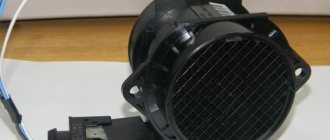
Mass air flow sensor (also known as a flow meter) is a sensor that determines the amount of air entering the car engine. Based on the obtained air consumption indicators, the ECU determines how much gasoline needs to be supplied to the combustion chambers.
The sensitive element of the sensor is represented by a thin platinum thread. During operation of the device, this thread heats up to a temperature of 1000 degrees and is cooled by the flow of passing air. The amount of air passed through is determined based on the temperature to which the sensitive element has cooled. The lower the temperature, the higher the conductivity of the platinum, and the greater the amount of current transmitted to the thread it conducts.
- How to use a multimeter to check the performance of the MAF on a VAZ-2110: video tutorial
The cost of the sensor is about 2-3 thousand rubles. The products of the German company Bosch have proven themselves well, while the owners of the fourteenth, on the contrary, do not respond entirely positively to the domestically produced mass air flow sensor.
Mass air flow sensor device
How to restore the mass air flow sensor?
The optimal solution for problems with the mass air flow sensor is to replace the faulty sensor with a new one. But since the cost of the device is about 2500-3900 rubles, many owners are trying to “revive” the old part.
There are four recovery methods:
- installation of additional resistance;
- blocking part of the air supply channel to the thermistor with aluminum tape;
- updating the engine control unit firmware;
- washing the sensor body and housing from dirt.
Installing additional resistance
Additional resistances are installed in the circuit connecting the sensor to the control unit. When an electric current passes, the voltage decreases, which can be brought to the required limits. The resistance value is selected experimentally. Most often, a 1 kOhm resistor is soldered to the yellow wire and a 15 kOhm element to the green wire.
Blocking part of the air supply channel
The repair principle is based on partially cutting off the air supply to the thermistor. Due to this, less intensive cooling is ensured and it is possible to bring the voltage value to the state of a working device. The cross section is selected experimentally with voltage monitoring using a multimeter. In some cases, owners block the supply channel by 70-80%. Aluminum tape is used for gluing.
Correcting the firmware of the engine control unit
An adjustment means a change in the calibration or operating schedule of the mass air flow sensor stored in the unit’s memory. The dependence graph is constructed in such a way that at a sensor voltage of 0.996 volts, the flow rate is considered equal to zero. But if the sensor fails and the starting voltage is 1.055 volts, then the control unit considers the air supply to be 1.8 kg when the engine is not running. Changing the graph using the MAF Corrector utility will allow you to set the flow rate to 0, which will improve engine performance. This method can be recommended to owners who are well versed in the control unit software.
Do-it-yourself cleaning of the air flow sensor
The air volume sensor is cleaned after it is detected that it is not working correctly. The procedure is performed by partially disassembling and removing the device body with active elements. At the same time, the body is washed and cleaned from remaining leaves and dirt deposits. In many cases, washing the air flow sensor on a VAZ 2114 does not help restore the device’s parameters.
Mechanical methods 2114 are prohibited, as is blowing dust with compressed air.
What products should be used to clean the sensor?
To clean sensors, there are special liquids supplied in pressurized aerosol cans. An example of such a product is a special air flow sensor cleaner Luftmassensor-Reiniger from Liqui Moly. There are similar liquids from other manufacturers. You can wash the sensor with a mixture of 70% isopropyl alcohol and 30% distilled water, after warming the device to 60-70 ºС with a hair dryer.
When washing the mass flow sensor it is prohibited:
- try to clean the sensor with cotton balls, hard objects and brushes;
- use household cleaning products;
- Use carburetor cleaners based on acetone or ether.
Cleaners based on heavy petroleum products, for example, WD40, will remove plaque from working parts, but will leave a greasy film that must be washed off with isopropyl alcohol. The use of ether-containing substances is not recommended due to the destruction of the compound filling and electronic components.
Algorithm of actions
Sequence of steps when washing the mass air flow sensor:
- Remove the sensor together with the housing from the engine air duct. The device is attached with a clamp to the channel and two bolts to the air filter housing.
- Unscrew the two screws securing the sensor to the housing. The bolts have a star head, but many owners unscrew them with pliers.
- Wash the measuring thermistors and the air passage channels with a cleaning agent. If the cleaning method with alcohol is used, the removed sensor is heated with a stream of warm air and placed in a container. The alcohol-water mixture is also heated to 60-70 degrees.
- Dry the sensor.
- Wash the sensor housing with warm soapy water. Rinse under running water and dry.
- Assemble the sensor and install it in place.
Detailed repair instructions
In practice, with the help of cleaning, the functionality of most sensors can be restored. At the same time, the car owner saves money. If, when checking the mass air flow sensor, it turns out that the voltage readings do not correspond to the norm, then you need to dismantle the device and wash it.
It should be remembered that you cannot use a toothbrush or cotton swabs for cleaning, since mechanical contact with the sensitive elements of the sensor can cause serious harm. Alcohol must be diluted with water in a ratio of 5 to 1. In addition to the listed means, in some cases you may need a 10-20 cc syringe with a needle.
Removal and cleaning of the mass air flow sensor must be carried out in the following order:
First, disconnect the block with the power wires. To do this, you need to press the release button, which is located at the bottom of the device. Unscrew the screws securing the unit to the air filter housing. Unscrew the connecting elements of the protective casing, screws, and remove the sensor itself. The most sensitive parts of the device are the temperature sensor wire, contacts
They need to be washed with extreme caution. To wash the resistor, the aerosol tube must be inserted into the upper channel of the sensor to a depth of approximately 10 millimeters
The procedure itself is carried out several times with short breaks of a few seconds. Penetrating lubricant WD-40, “Hado” is applied for cleaning several times with breaks of 30-40 seconds. At the last stage, you need to let the device dry thoroughly. After this, the sensor is installed in place, and its voltage is checked using a tester. If all indications are normal, then the procedures performed can be considered successful. Otherwise, you will have to change the mass air flow sensor.
Thus, if the air flow sensor partially loses its functionality, you should not rush to purchase a new device. It is advisable to spend 15-20 minutes dismantling and cleaning the old device. This will restore its functions and help save money.
Checking the mass air flow sensor
Before you start experimenting, take the time to read the service manual. It describes in detail what a mass air flow sensor on a VAZ 2114 is and how to replace it.
We are looking for a sensor. Open the hood and find the air filter pipe. The mass air flow sensor is located on it, which determines the flow of air passing through the filter. I will give several options on how to check the mass air flow sensor yourself.
- Disable the sensor. Disconnect the block with wires from the connector by pressing the latch located below. Start the engine (1500 rpm or more). The controller understands the shutdown of the mass air flow sensor as an emergency condition and prepares the fuel-air mixture based on the position of the throttle valve. Try driving a short distance. If the car accelerates noticeably faster, this indicates a non-working mass air flow sensor. I would like to note that in the disabled state for ECUs Y7.2 and M7.9.7. RPM doesn't increase!
- Replacing the controller firmware. The original ECU firmware could have been replaced with an alternative one. In such a situation, we do not know which algorithm is prescribed in the case of operation in the mode discussed in the first paragraph. The throttle valve has a stop under which you need to place a thin plate (about 1 mm) to raise the speed. Then you need to disconnect the chip with the sensor. If the sensor is faulty, the engine should stall. If the engine is running, then the reason is due to the firmware features: the IAC steps are written incorrectly.
- Voltage measurement. Testing gives good results when working with Bosch sensors. You will need a multimeter. Select the DC voltage measurement mode and set the maximum value to 2 V.
The connection diagram for the VAZ 2114 looks like this:
- yellow – incoming signal;
- gray with white – power output;
- green – grounding;
- pink with black – output to the main relay.
The colors may be different, but the sequence of connectors is the same.
Next, you need to turn on the ignition with the engine off. Connect the red (positive) probe of the tester to the yellow output, and the black (negative) probe to the green. Multimeter probes are inserted along the specified wires directly through the rubber seals of the connectors without damaging the insulation. For prevention, I recommend moistening the probes with WD-40. Intermediates or needles are not recommended due to the additional error they introduce. Measure the voltage. Compare the result with the table:
| Voltage, V | State |
| 1,01 – 1,02 | Good. The sensor is almost new and will last a long time. |
| 1,02 – 1,03 | Satisfactory. The sensor is old, but works properly. |
| 1,03 – 1,04 | Bad. The resource is almost exhausted. Will have to replace it soon. |
| 1,04 – 1,05 | Deplorable. The resource has been exhausted. Suitable for use if there are no alarming symptoms. It is advisable to replace |
| 1.05 – and above | Emergency. The sensor is faulty (possibly for a long time). Replacement is required. |
A newly installed sensor gives an output voltage of 0.996–1.01 V. Over time, it increases. A higher value means a higher percentage of wear.
Voltage data from the sensors is recorded by the on-board computer and can be viewed by selecting the appropriate group of parameters.
Inspection and cleaning. Use a Phillips screwdriver to loosen the clamp holding the air intake pipe. We remove the corrugation and check whether there are traces of oil and/or condensation inside it, as well as on the inner surface of the sensor. Normally they shouldn't be there. The sensing element of the mass air flow sensor often breaks due to dirt getting on it. This can easily be avoided by regularly replacing the air filter. Reasons for oil getting into the air flow sensor:
- the permissible oil level in the crankcase has been exceeded
- The oil separator of the ventilation system is clogged
The sensor is attached to the pipe with two screws. We unscrew them with an open-end wrench (x10) and remove the sensor itself. There is an entrance at the front, which must be protected from the leakage of untreated air with an o-ring rubber seal. If it is missing or remains in the filter housing, dust clogs the sensor input grid. It needs to be cleaned, the seal installed, the leaks checked and the sensor put back in.
Comparison with a working sensor. From personal experience, I was convinced that the most accurate test is to install a sensor that is known to work and compare the behavior of the engine with the “native” one.
In addition to the options considered for how to check the mass air flow sensor yourself, you can also contact a service center that has special equipment and carry out 100% diagnostics, for example, using the method of evaluating an oscillogram.
DMVR device on VAZ-2114
General view of the DMVR sensor
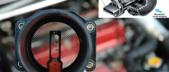
Before proceeding directly to diagnostics, you need to know the design features and structure of this sensor. Let's look at the diagram of the DMVR device in the image.
DMVR device diagram
Causes of sensor malfunction
The next step before diagnosis is to identify the causes of the malfunction, as well as factors that may influence the mass air flow sensor to fail.
Check Engine icon on instrument panel
In this case, if you connect to the electronic engine control unit, you can identify the following malfunction: “Insufficient MAF signal level.” This is what means that the sensor has failed.
Main features
So, let's look at the main signs of a malfunction of the DMVR:
- Malfunctions in the operation of the main power unit, namely: floating speed, the car stalls at idle.
- A drop in acceleration dynamics is also one of the fundamental factors in the interruption of operation of a given unit.
- When changing gears, the car simply stalls.
- Increased fuel consumption. This is due to the fact that the fuel mixture ratio is incorrect.
Now that the signs of a malfunction are clear, we can consider the factors that cause the failure of the DMVR:
- Destruction or breakage of wiring inside the product.
- Loose fixation of the wire block.
- Damage to the inside of the element.
- Oxidation of contacts.
- Wear or burnout due to short circuit.
Often the air flow sensor fails after washing the engine.
Checking the mass air flow sensor using a multimeter
In order to check the mass air flow sensor, it is not necessary to go to a car service center and spend a lot of time and money. To do this, you need a regular tester or multimeter, which can be bought for 300 rubles on the market.
Location of the DMVR sensor
To check the DMVR, you need to know the pinout of the contact group.
So, let's look at the pinout of the mass air flow sensor:
- Contact No. 5 (in Bosch sensors, as a rule, yellow wires come from it) - is responsible for supplying an incoming signal from the ECU;
- Contact No. 4 (gray or white) - is responsible for powering the device;
- Contact No. 3 (green wire) is responsible for grounding;
- Contact No. 2 (pink-black) is the wire through which information from the sensor is transmitted to the main relay of the fourteenth.
To determine serviceability, you do not need to remove the sensor. The multimeter is set to measure direct current up to 20 volts. Next, follow the step-by-step instructions:
The principle of checking the DMVR sensor
- We connect the red wire from the multimeter to pin 5, and the black wire to pin 3.
You can connect contacts using a pin
Without starting the car, turn the ignition. We look at the multimeter readings, the explanation of which is given below.
| Tester readings (voltage, V) | Air flow sensor condition |
| 0.006 — 1.01 | Only new sensors produce this voltage; after several weeks of operation it increases by several hundredths; |
| 1.01 — 1.02 | Normal operating voltage of a device in constant operation; |
| 1.03 — 1.04 | The device has used up approximately half of its working resource; |
| 1.04 — 1.05 | The MAF voltage is in an extremely worn condition, replacement is recommended; |
| Above 1.05 | Such a sensor does not work, or it works but sends distorted signals to the ECU. |
Diagnostics of mass air flow sensor
If there is no similar sensor, then there are other ways to check the performance of the flow meter:
- visual diagnostics;
- checking while driving;
- determining firmware compliance;
- diagnostics with a tester.
Visual inspection
Before checking the device using this method, it must be removed from its mounting location. To do this, the pipes are disconnected from the housing of the air filter element. The inside of the controller must be dry; traces of motor fluid and condensation are not allowed. Often the device breaks down due to non-compliance with the air filter replacement intervals, as a result of which dirt remains on the sensitive component. This leads to the controller giving incorrect readings.
If there are traces of motor fluid on the internal cavity of the controller, this indicates a high level of lubricant pressure in the power unit. The reason may be a clogged crankcase ventilation. When checking, you need to make sure that the sealing element is located in the right place where the corrugation is installed. This part may have become stuck in the air filter housing. With this problem, air leaks into the engine, which gets inside with dust and contaminates the regulator.
Diagnostics on the move
It is necessary to disconnect the plug with the power circuit from the sensor and start the engine, and then disconnect the block. The Check Engine indicator will appear on the dashboard. The minimum engine speed should increase to 1500 per minute. If the engine begins to operate more stably after turning off the device, this indicates a malfunction. The sensor needs to be replaced.
User Igor Belov spoke about several methods for diagnosing the flow meter, including checking while driving.
https://youtube.com/watch?v=HO6ITsSSoDY
Compliance of the mass flow sensor with the ECU firmware
To check the firmware compliance, you need to take a 1 mm thick plate and place it under the damper stop, this will lead to a change in engine speed. Then the block with wires is disconnected from the controller. If the car engine does not stop, then the reason is the firmware of the microprocessor module, idle speed controller without a flow meter in emergency mode.
DMRV failure - how to identify
If this control element fails, a lamp lights up on the dashboard, signaling the need to check the car’s power plant.
The main signs of failure of the mass air flow sensor:
- power is lost;
- the speed also drops;
- a lot of fuel is consumed;
- the engine starts poorly.
There are several ways to determine the performance of the mass air flow sensor:
- by turning off;
- multimeter;
- upon inspection.
In the first case, replacing the sensor is not difficult. Just disconnect the connector (pinout is not required here) and turn on the engine. The ECU must go into emergency mode. In this case, the supply of the combustible mixture is regulated only by the throttle valve. At the same time, at idle, the power unit produces 1.5 thousand revolutions. Next, you will need to drive a certain distance. If the car accelerates faster than usual, we can confidently say that the mass air flow sensor has broken down.
It is also worth pointing out that the multimeter is useful only if the car is equipped with a sensor manufactured by. The check goes like this:
- The scale on the tester is set to 2 volts of DC voltage;
- the red probe is attached to the yellow wire, the black one to the green;
- turn on the ignition.
If the readings are within:
- 1.02 volts - then the sensor is working;
- 1.03 – acceptable value;
- 1.05 is the limit.
In cases where the measured voltage is higher, a breakdown should be considered. In order to determine from the appearance of the control device whether it is working, you will need to carefully examine the tubes leading to it from the inside. They are easy to dismantle using a Phillips screwdriver. First of all, unscrew the clamp securing the corrugated sleeve. The surface of this tube must be clean, without oily films.
- How to check the mass air flow sensor on a VAZ 2114 car with your own hands?
The presence of dirt inside the sensor is a clear sign of its malfunction. As a rule, the problem occurs when the car owner forgets to change the air filter on time.
Oil leaks are usually evidence of excess lubricant in the system or improper operation of the shut-off valve. Such contamination significantly reduces the service life of the mass air flow sensor.
Then it is necessary to dismantle the sensor itself. To do this, you need to use a 10mm socket wrench. After the control device is removed from the filter, it will need to be inspected. In a situation where the rubber gasket of the sensor remains in place, then we can speak with almost one hundred percent certainty about a breakdown of the mass air flow sensor.
