Ignition system gazelle 402 carburetor
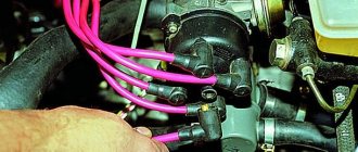
The ZMZ-402 and ZMZ-4021 engines are equipped with a non-contact ignition system consisting of a transistor switch, an ignition distributor of type 19.3706, an ignition coil of type B116 or B116-01, spark plugs and high-voltage and low-voltage wires.
The ignition distributor sensor (1908.3706) is non-contact, with a control pulse sensor (generator) and built-in vacuum and centrifugal ignition timing regulators.
The distribution sensor performs two functions: it sets the moment of sparking and distributes high voltage pulses among the cylinders in accordance with the order of their operation.
For this purpose, a slider mounted on the shaft of the sensor-distributor is used. An interference suppression resistor* is installed in the slider.
Instead of a resistor, part of the sensors has a cover with a central carbon contact.
The switch (1313734) opens the power supply circuit of the primary winding of the ignition coil, converting the sensor control pulses into current pulses in the ignition coil.
Removal
1. Unscrew nuts 1 and disconnect low-voltage wires from coil terminals 3.
Disconnect high-voltage wire 4 from the ignition coil.
Unscrew nuts 2 and remove coil 3 (Fig. 2).
Examination
1. Ignition coils B116 and B116–01 are checked on a mod. K–295.
The coil must ensure uninterrupted sparking at the spark gap with a gap of 7 mm at a rotation speed of the ignition distributor shaft of at least 2500 rpm.
Inspect the coil. If the plastic cover has chips, cracks, signs of heating or oil leakage, replace the coils.
Check the resistance of the primary winding of the ignition coil by connecting an ohmmeter between the low voltage terminals.
The ohmmeter should show a resistance of 0.48–0.72 ohms.
Then check the resistance of the secondary winding by connecting an ohmmeter between the high voltage terminal and the “K” terminal of the coil.
The ohmmeter should show a resistance of 13,200–19,800 ohms. If the measured parameters differ, the coil must be replaced.
Ignition system switch
A transistor switch type 131.3734 or 90.3734 is installed on the left mudguard behind the battery.
It converts the control pulses of the Hall sensor in the ignition distributor into current pulses in the primary winding of the ignition coil.
Since the switch generates a large amount of heat during operation, it is necessary to periodically clean the switch housing from dirt and dust and not cover it with foreign objects.
Photo report: How to check the ignition coil of a CDI scooter?
I don’t know what this is connected with, but most owners of scooters and motorcycles equipped with a CDI ignition system, when problems arise with a spark on a spark plug, immediately blame the ignition coil. To all my well-reasoned arguments in favor of the fact that in addition to the coil in the electrics of a scooter there are also a bunch of devices that ensure sparking between the electrodes of the spark plug: a generator, an induction sensor of the generator, a switch, wires in the end - they make glassy eyes and everyone repeats their catchphrase as one : “Can’t you call her?” It’s impossible, my dears, it’s impossible!
No, of course I can make an intelligent person and, for the sake of respectability, poke the coil in front of you with a tester, as collective farm gurus do. But I won't do that today. For one simple reason: it is possible to “ring”, measure the resistance of the coil windings, but what will this give us? Well, the tester will show us the treasured numbers on the display, so what? And if there is an internal turn-to-turn short circuit in the coil windings, a manufacturing defect, or the winding of one of the coils has burned out. Do you think you can identify all these faults using a tester? I assure you that it is not.
It will be useful Choosing engine oil for a mitsubishi asx engine: photos and videos
Therefore, since for that matter, and you are inclined to believe that the lack of a spark can still somehow be connected with the ignition coil, we will go from the opposite. Namely: today we will learn how to check not the coil itself, since this is useless and does not give anything, but we will check the electrical parameters of the devices that ensure the functionality of the ignition coil. This approach to diagnosing this type of device is more effective than the usual “testing” of the windings for open circuits or measuring resistance.
Switch Problems - Symptoms and Signs
A switch is one of the elements of a car's electrical equipment. His task
– ensuring normal operation of the contactless ignition system. The assembly is fastened in the engine compartment.
The device is different
reliability, ability to withstand severe vibrations and shock loads. This is very important, because the switch housing contains sensitive electronics.
At the heart of the VAZ switch
– standard L 497 microcircuit, which controls an “NPN” type transistor.
>Scheme feature
– possibility of programming by the user and setting the required delay coefficient. Starting a cold engine directly depends on the correctness of this indicator.
Thanks to precise settings
, you can speed up the crankshaft rotation speed (while eliminating failures in operation) and guarantee high-quality traction of the power unit.
The main parameters of the switch device include:
Voltage range - from 6 to 16 Volts; operating voltage level - 13.5 Volts; ensuring an uninterrupted spark when the crankshaft rotates in the range from 20 to 7000 rpm;
switching current – from 7.5 to 8.5 A.
Symptoms of a Switch Problem
One of the main symptoms of a faulty switch is loss of spark.
. The engine starts hard and stalls from time to time, causing interruptions in operation.
But don't rush to replace it
- it is important to verify the reason, because
loss of spark can occur for a number of reasons
- failure of the Hall sensor, rupture of the timing belt, malfunction of the ignition coil, poor contact in the distributor cap, problems in the wiring, and so on.
Therefore, first of all, a comprehensive diagnosis is necessary. The fastest and most effective way in this case can be a car diagnostic scanner. For the most part, this type of device is quite easy to use and has an affordable price. Of those presented on our market, we can recommend paying attention to the multi-brand scanner Scan Tool Pro Black Edition.
Types of switches
According to their functional features, switches are divided into three main types:
- standard;
- sports;
- a switch that has the option of adjusting the ignition timing.
A distinctive feature of a standard or, as it is also called, stock switch is its stability. It strictly corresponds to the parameters of the car in which it is installed.
Stock switch
installed in the car at the factory. As a rule, manufacturers make sure that the device can ensure maximum reliability and durability of the entire engine. As a rule, they have a speed limiting unit, which in some cases can save the lives of the driver and passengers.
Sports Switch
increases the upper limit of engine speed. It can be installed in a car at the request of the car owner. The problem is that only experienced specialists can perform such a procedure, and the installation will require the replacement of a number of other parts. However, you should still remember that a sports switch is a risk of an accident, especially if an inexperienced driver is behind the wheel.
Commutator with phase correction
equalizes engine torque, compensating for lack of power. As a result, the car receives good acceleration data and smooth engine operation at different speeds.
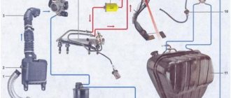
Wiring diagram for Gazelle 402 engine: do-it-yourself replacement
Having become an indispensable vehicle, the Gazelle with the 402 engine still requires attention over the years.
Electrical wiring is not listed among the parts subject to scheduled replacement, however, an electrical diagram is often required when carrying out repair work in the engine compartment.
Native 402 engine for Gazelle
Equipped with a ZMZ-402 carburetor engine, the car successfully exhausts its service life, and when the time comes for a major overhaul, many owners think not only about restoring, but also about reconfiguring its operation.
And since carburetor versions of power units have become a thing of the past, the question of the prospects for using a restored engine is urgent.
Electrical system of a Gazelle car
The transition to multi-valve injection engines is possible and even recommended by the automaker, but owners are not always satisfied with this approach, especially from the financial side.
Advice: Be that as it may, when removing the motor for overhaul, the owner has the opportunity to replace the old electrical wiring.
If the resource of the restored power unit inspires optimism, and you have a Gazelle wiring diagram at hand, the 402 engine may well last for hundreds of thousands of kilometers.
Electrical wiring diagram for Gazelle 402 engine
Replacing wiring on a Gazelle car
The reasons causing the need to replace the electrical wiring according to the diagram in Gazelle cars are not only due to the overhaul of the power unit, but also:
- Due to natural wear and tear of wires;
- Delamination of insulation due to natural aging;
- Mechanical damage (kinks, scuffs);
- Short circuits in one or another electrical circuit;
- Oxidation of contacts and connectors.
Additional replacement materials
In addition to purchasing new electrical wiring, those corresponding to the motor used must also be replaced:
- High voltage wires;
- Electronic switch (in later versions of motors of the ZMZ-402 series);
- Ignition coil;
- Battery charge level relay;
- Fuse block contact group;
- Egnition lock.
Places requiring installation work
Laying the wiring harness is not a difficult task, especially since the places for their attachment to the frame are provided initially (gutters, service holes, etc.).
Gazelle interior with disassembled dashboard
However, according to complexity, replacement work is divided into areas of responsibility:
- Engine compartment;
- Vehicle interior;
- Rear part of the body.
The easiest part in terms of connection is the rear part of the car, where you only need to secure the harness and connect the rear lights and the fuel level sensor in the gas tank. The interior and engine compartment are more complex.
Installation of wiring on a Gazelle car
The wiring for Gazelle 402 is divided into the indicated zones.
Having laid out a new set of wires in a free place, its orientation will be immediately noticeable:
- The longest and thinnest tourniquet is intended for the back;
- The shorter one is for the interior;
- The largest number of wires and connectors is for the engine compartment.
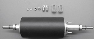
Ignition coils for a Gazelle car with the engine: ZMZ402, ZMZ406, ZMZ409, UMZ4216, EvoTech
The ignition coil is one of the main elements of a car's electrical system. The short circuit performs the function of converting a low-level signal coming from the switch or ECU into high voltage, which subsequently goes to the spark plugs, through the ignition wires, to ignite the fuel mixture. The more correct technical name for the ignition coil is a high voltage transformer that generates U>2000v at the output.
Since its release (1994), and over the years, ignition coils of various engineering designs have been installed on the Gazelle car. This depended mainly on the engine installed on the car and its control system (CMS).
Ignition coil ZMZ 402
The first Gazelle with a ZMZ 402 carburetor engine was equipped with: a switch 131.3734, which supplies voltage to the contactless coil B-116, which, in turn, generated high voltage to the ignition distributor 1908.3706 (distributor).
B-116 coil malfunction
The multimeter is set to the lowest measurement limit of 200 ohms. If the resistance does not fit within the specified parameters, then the ignition coil should be replaced.
Ignition coil ZMZ 406
In 1998, a new engine from the Zavolzhsky Motor Plant ZMZ 406 appeared on Gazelles. The engine, like its predecessor, was carburetor, but it did not have a distributor and switch, instead of which there was a microprocessor control system Mikas-7.1, an absolute pressure sensor, a synchronization sensor , coolant temperature sensor and two coils 406.3705. The ignition coils supplied high voltage, alternately, to cylinders 1-4 and 2-3.
Adjusting the ignition system ZMZ 402
The operation of the engine, its efficiency and reliability directly depend on the correct settings of the ignition system. In this article we will look at the design and components of the ZMZ 402 ignition system, as well as the procedure for setting the ignition timing
Ignition system elements
One of the main systems necessary for a successful engine start is the ignition system. For gasoline engines, the fundamental design of ignition systems differs very slightly - there are two types:• Contact system• Contactless system
The ignition system consists of the following components: 1. Coil2. Distributor-spark interrupter (distributor)3. Switch4. Spark plugs5. Ignition switch6. Starter
7. Additional resistance (in some cases)
How the ignition system works
For the ZMZ 402 model, this order looks like this:
1-2-4-3
The car engine is started by turning the key in the ignition switch - at this moment the charge from the battery is supplied to the starter, which begins to rotate the crankshaft, activating the distributor (via the drive). At this very moment, electric current is supplied to the coil, then through the commutator the charge is supplied to the spark distributor (distributor), which in turn distributes the current through the wires to the cylinder spark plugs.
IMPORTANT to know that the switch is a block of transistor switches that serves to control the currents that pass through the inductor.
Early ignition
One of the most common problems with the ignition system is too early an ignition timing angle - this is when, when fuel is supplied to the engine cylinder, the working mixture of gasoline and air in the combustion chamber ignites much earlier than the piston approaches top dead center. If the initial ignition timing is set too early, then problems with the vehicle's performance may occur. To avoid this, you should pay attention to signs of early ignition.
And this is:• The engine does not start the first time (the crankshaft turns in the opposite direction when starting the engine)• Unstable operation of the engine at idle• Detonation of unburned fuel (a chirping sound appears that does not disappear when the speed increases)• Carbon deposits on the spark plugs ignition (fuel that is not completely burned settles on the spark plug)• Shots into the muffler (fuel burns due to misfire of the ignition)• Black smoke from the muffler (fuel that is not burned in the combustion chamber burns out)• Increased fuel consumption
Late ignition
On engines with a carburetor power supply system, late ignition is the ignition of the fuel mixture at the moment when the piston has already reached top dead center or has already passed it. When the engine operates this way, fuel consumption increases, power and throttle response deteriorate. The main signs of late ignition are:• Trouble starting the engine (several attempts are needed)• Sluggish vehicle dynamics while driving (the engine stalls when the speed increases)• Light gray or white spark plugs• Shots in the carburetor (fuel burns out in the intake manifold )
• Engine overheating (the mixture burns out during the expansion stroke, which contributes to engine overheating)
Procedure for adjusting the ignition system
To correctly install the ignition on the ZMZ 402 engine, the following factors must be taken into account:• The engine operating order is 1-2-4-3• The distributor rotor rotates counterclockwise• The backlash on the spark plug should be no more than 0.8 mm• The resistance value of the resistor on the distributor should be from 5 to 8 kOhm• The resistance value on the spark plug ranges from 4 to 7 kOhm• The resistance of the stator winding varies from 0.45 kOhm to 0.5 kOhm
Label matching
To begin setting the correct ignition timing, you need to turn the crankshaft to a position that indicates 5 degrees. This is done as follows - you need to set the first cylinder at top dead center (end of the compression stroke). To do this, you need to align the middle mark on the crankshaft pulley with the mark on the cylinder head.
ATTENTION. The compression stroke on the first cylinder can be set if the distributor has not been removed before - by opening its cover, the slider will stand opposite the internal contact of the wire connecting to the spark plugs of the first cylinder.
If it is not possible to determine the compression stroke in this way, then it is necessary to unscrew the spark plug from the first cylinder and plug the hole with a rag or paper. Then you should start cranking the crankshaft until the paper-shaped plug is removed with the help of air created inside the cylinder. This will be the moment of compression.
Advance angle adjustment
Next, you need to loosen the octane corrector bolt, which is located on the distributor. A 10mm wrench will come in handy here. Then the advance angle is set approximately in the middle of the scale (this will be zero). Next, using the same 10mm wrench, you need to loosen the bolt securing the octane corrector plates.
The next step is to rotate the distributor housing so that both marks coincide - the red mark on the rotor head and the mark on the stator. When the housing is installed in the desired position, it is necessary to fix the distributor housing with one hand and tighten the bolt with the other.
Checking the correct installation of the ignition
The correctness of the set ignition timing is checked while the car is moving - at a speed of 50-60 km/h, the gas pedal is sharply pressed, a short-term detonation should follow (1-3 seconds). If detonation disappears after this time, then the moment was chosen correctly. You can set the ignition more accurately using a strobe light.
This short guide will help you set the ignition yourself without resorting to the help of specialists at home.
Source: https://remruk.info/regulirovka-systemy-zazhigania-zmz-402/