Nevada 1976
Modern engines have a rather complex design and are controlled by an electronic control unit based on sensor signals. Each sensor monitors certain parameters characterizing the operation of the motor at the current time and transmits information to the ECU. In this article we will look at one of the most important elements of the engine management system - the camshaft position sensor (CPS).
What is DPRV
The abbreviation DPRV stands for camshaft position sensor. Other names: Hall sensor, phase sensor or CMP (English abbreviation). From the name it is clear that it is involved in the operation of the gas distribution mechanism. More precisely, based on its data, the system calculates the ideal timing of fuel injection and ignition.
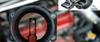
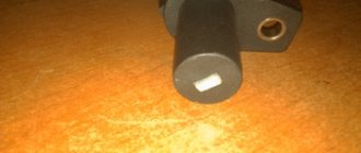
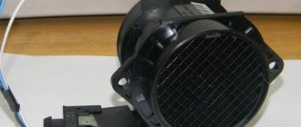
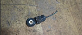
Appearance of DPRV
This sensor uses a reference voltage (power supply) of 5 volts, and its main component is a Hall element. It itself does not determine the timing of injection or ignition, but only transmits information about the moment the piston reaches TDC in the first cylinder. Based on these data, the injection time and duration are calculated.
In its operation, the DPRV is functionally connected to the crankshaft position sensor (CPS), which is also responsible for the correct operation of the ignition system. If for some reason the camshaft sensor fails, the basic data from the crankshaft sensor will be taken into account. The signal from the DPKV is more important in the operation of the ignition and injection system; without it, the engine simply will not work.
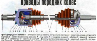
DPRV position (depending on the design of the internal combustion engine)
DPRV is used on all modern engines, including internal combustion engines with a variable valve timing system. It is installed in the cylinder head depending on the design of the engine.
Where is the camshaft position sensor located?
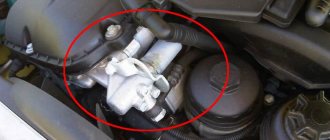
On most cars, the DPRV is located in the area of the cylinder head . To find it, you need to focus on the position of the camshaft. It can be located on the left or right side of the engine. The location of the camshaft sensor varies depending on the make and model. It can usually be found near the top of the belt location or in protected parts of the wiring located at the front of the engine. Also, sometimes DPRV is installed in the rear of the cylinder head. And some automakers put it in a special compartment under the hood (an example is General Motors cars).
Below are several examples of the location of the DPRV on different machines.
DPRV for Opel Astra DPRV for VAZ 2114 DPRV for VW Polo
The essence and principle of operation
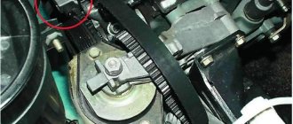
The camshaft sensor on the VAZ 2114 (phase sensor) is designed to generate pulse signals based on information about the engine operating cycle. It is located on the engine in the cylinder head area, near the air filter in the 8-valve version and on the drive camshaft near the generator in the 16-valve version.
The device is an element of on-board engine control and is installed exclusively on injection engines. It is found in all VAZ 2114 that comply with EURO-3 and have sequential injection of the fuel mixture.
The phase sensor design consists of:
- Sensitive part.
- Signal converter.
The second includes:
- Bridge circuit.
- Open collector output stage.
- Operational amplifier.
The operation of the sensitive element is based on the Hall principle. It is a circuit that captures magnetic field fluctuations. When the microcircuit receives a signal, and this happens when the valve head, which is a magnetically conductive material (steel), passes by it, it transmits the signal further through the device. The information received is analyzed by the on-board system of the machine and, based on the received data, controlled injection occurs.
How the sensor works
The DPRV itself is responsible for controlling the valve timing. This is not enough for a complete picture of the operation of the internal combustion engine. Therefore, the ECU (electronic control unit) constantly compares the position of the crankshaft and camshaft relative to each other. This eliminates the occurrence of errors when the timing belt is displaced relative to the piston group (the belt or chain has jumped one or more gear teeth).
If you ask a car enthusiast what a phase sensor is, he will answer: “Hall sensor.” This popular name arose because most DPRVs operate according to the Hall principle. The illustration shows how the system works.
When two parts of the Hall elements are combined, an electrical pulse is formed in the inductor. In this way, it is possible to fix the position of the timing camshaft in a non-contact manner. The ECU control algorithm monitors the passage of the control point at each camshaft revolution and forms the correct picture of when and which valve is open (closed). At the same time, the position of the crankshaft is analyzed, and the fuel mixture is formed and supplied to the combustion chamber in a timely manner. In addition, together with information from lambda probes, the correctness and cleanliness of the exhaust is monitored. That is, DPRV affects not only the quality of engine operation as a whole, but also supports the environmental friendliness of the car.
How to check DPKV yourself - 3 different ways
Before you start checking the synchronization sensor with instruments, you must mark its initial position on the engine. After removing the electronic device, inspect it for external damage. If the sensor is dirty, it is necessary to clean it, including removing corrosion from the contacts, if any, using gasoline or alcohol. If there is no external damage to the sensor, you can begin to diagnose it using instruments.
How to check the crankshaft position sensor with an ohmmeter
In order to check the crankshaft sensor with an Ohmmeter, you must perform the following procedure:
- The first thing to do is to inspect the device while it is installed on the car, or rather, check for a gap between it and the synchronization disk. It is quite possible that there is no gap there due to the fact that dirt has adhered to the sensor or disk, which led to the violation.
- If everything is in order with the gap, we will remove the device from the car.
- The next stage is assessing the external state. The sensor body must be intact, without signs of damage, the core must be clean, the contact terminals must be free of traces of oxidation, and the wires must not be damaged.
- If external contamination is visible on the DPKV, you can wash it before checking (to do this, use only pure gasoline or alcohol), and also clean the contacts with a file.
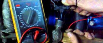
- After cleaning, rinsing and drying, you can start taking measurements. To do this, switch the multimeter to ohmmeter mode and connect the probes to the sensor contacts.
- When measuring, a working DPKV should show a resistance in the range of 550-570 Ohms.
Checking the inductance of the crankshaft sensor
Checking the inductance of the crankshaft position sensor is a more complex method. To do this you will need:
- voltmeter, preferably digital;
- megohmmeter;
- inductance meter;
- network transformer.
For correct indicators when measuring the sensor, the recommended air temperature is 20-22 0 C. We measure the winding resistance with an ohmmeter and the method indicated above.
To measure the inductance of the crankshaft speed sensor winding, an inductance meter (inductive coil, capacitance and resistance) is used. The inductance should be in the range of 200-400 MHz.
Using a megohmmeter, the insulation resistance is checked. This parameter at a voltage of 500V should not be higher than 20 MOhm.
If during the repair of the sensor the synchronization disk is inadvertently magnetized, then demagnetization is carried out using a network transformer. Based on the results obtained during test measurements, you receive data about the sensor’s malfunction, or, conversely, its serviceability
When installing an old or new sensor, carefully install it in the seat according to the marks. Do not forget about the distance that should be between the synchronization disk and the core (0.5-1.5 mm)
Based on the results obtained during test measurements, you receive data about the malfunction of the sensor, or, conversely, its serviceability. When installing an old or new sensor, carefully install it in the seat according to the marks. Do not forget about the distance that should be between the synchronization disk and the core (0.5-1.5 mm).
How to Test a Crankshaft Position Sensor Using an Oscilloscope
A digital oscilloscope allows you to effectively monitor and find faults in injection system sensors. Now we will talk in detail about checking the crankshaft sensor using an oscillogram:
The crankshaft position sensor (CPS) is the most important in the injection system; it synchronizes the operation of the electronic engine control unit. The VAZ DPKV signal is a series of repeating electrical voltage pulses generated by the sensor when the crankshaft rotates.
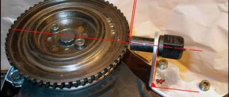
The drive disk is a 60-2 gear, i.e. 58 equidistant teeth and two missing teeth for synchronization. When the drive disk rotates together with the crankshaft, the depressions change the magnetic flux in the sensor's magnetic circuit, inducing alternating current voltage pulses in its winding. The oscillogram of the inductive DPKV has the following form:
Here it is worth paying attention to the signal amplitude and pulse shape. If the turns in the sensor winding are short-circuited, the signal amplitude will be reduced
Also, from the oscillogram it is easy to calculate the runout of the drive disk and damage to the teeth. On some foreign cars, a Hall sensor is used as a DPKV, producing rectangular pulses.
And this is how the crankshaft and camshaft position sensors of Nissan engines work synchronously. Based on the rising edges of the signals, the displacement of the shafts relative to each other can be determined.
Characteristic symptoms of the problem
Practice shows that a malfunction of the camshaft position sensor does not lead to engine failure and immobilization of the vehicle. The engine continues to operate with some deviations that interfere with the normal operation of the car. Symptoms of DPRV failure are quite vague and similar to problems with other measuring elements:
- Unstable engine operation at idle and while driving.
- Instead of dynamic acceleration, after pressing the gas pedal, there is a series of small jerks and a sluggish increase in speed.
- The power of the power unit decreases. The effect becomes noticeable when the load increases - on a hill, sharp acceleration, while towing a trailer.
- The Check Engine light on the dashboard does not always come on. But many drivers note that if the meter is faulty, the display flashes after the crankshaft speed increases to 3000 rpm or more.
- Fuel consumption is naturally increasing.
If the measuring element is faulty, the control unit prepares and supplies an enriched air-fuel mixture to the cylinders.
This results in an increase in gasoline consumption and unstable idling. Jerks and drops in power are caused by untimely supply of a spark - the controller “does not see” the end of the compression stroke in the cylinder and cannot clearly determine the ignition timing. On various car models, additional symptoms of a malfunctioning camshaft sensor are noted:
- the engine suddenly stalls while driving, but starts without problems;
- cold starting of the engine becomes difficult;
- on cars equipped with a robotic gearbox, difficulties arise with automatic gear shifting;
- the engine “troits” - skipping ignition cycles is heard, sometimes popping sounds are observed in the exhaust manifold;
- On some cars, the power plant fails due to lack of sparking.
Reference. The service life of the element is quite long. On domestically produced cars, the resource reaches 80–100 thousand km, on imported cars – 150 thousand km. When searching for the causes of a malfunction, you can focus on the specified periods.
Driving with a broken air pressure sensor is acceptable for a short period. Jerking, rich fuel mixture and electronic errors accelerate the wear of spark plugs and engine parts. After detecting the listed symptoms, you should send the car for diagnostics or find the source of the problem yourself.
Consequences of a malfunction
Like any element of a technical system, the DPRV can break down. Failure most often occurs due to the rupture of the thin wire that makes up the coil, or the adhesion of metal dust to the magnetic circuit. Problems with the winding arise when the sensor is used for a long time (car manufacturers recommend changing it every 100 thousand km). The adhesion of metal shavings occurs when internal combustion engine parts (bearings, dampers, fasteners) wear out.
A faulty sensor will cause problems in the operation of the power unit, the manifestation of which depends on its modification. Frequent consequences:
- Locking the gearbox. The transmission begins to operate normally only after the internal combustion engine is restarted, but the problem appears with a certain cyclicity.
- Reduced torque. Loss of power will not allow the car to accelerate even to 60 km/h.
- Engine stops, refuses to start again.
- Car jerking at speed.
- Misfires, starting problems, failures in dynamics.
Electronics constantly monitors the state of the sensor. If there are deviations in the signal formation, the corresponding pictogram will light up on the car’s dashboard, indicating a malfunction. In the future, you can read the error code - it is automatically saved in the memory of the on-board computer.
How to check the camshaft position sensor with a multimeter
When carrying out the check, it must be taken into account that the location of the sensor may vary depending on the make of the vehicle. In most cases, this device can be found near the engine cylinder head.
To inspect the sensor, unscrew and remove the chip.
Test scheme
It is important to understand that the presence of a diagnostic message about a sensor failure may mean that it is not the sensor that is faulty, but the connector, connecting wires, and devices working with it.
Here's how to check the camshaft sensor with a multimeter:
- You need to find this sensor and disconnect it. First you need to inspect for damage or rust. It is important to ensure that there are no melt marks or breaks on the wires.
- Make sure that the wires do not touch either the spark plugs or the ignition coils. In this case, interference may occur that drowns out the sensor signal.
- It is necessary to use a multimeter to check. It is used to check the signal on the wires connected to the sensor. If it is magnetic, then you will have to measure alternating voltage.
- You need to ask another person to turn the ignition and not start the engine. One of the tester wires is connected to ground, the others to the sensor wire. If there is no voltage, then there is a complete failure of this component.
- Next, start the engine and connect the multimeter wires to the sensor wires. The parameters must correspond to the data specified in the technical manual of the vehicle.
For a three-wire sensor, the check is done in a similar way. However, you will need to check the voltage between each pair of three wires.
How to make sure the DPRV is working?
The easiest way to check the camshaft sensor is to connect a car scanner or a computer with an installed program corresponding to the make of the car to the diagnostic connector of the car. If the element is faulty, then after starting the engine the device will display the following error codes:
- P0340 – there is no signal from the camshaft position detector;
- P0341 – valve timing does not coincide with the compression/intake strokes of the cylinder-piston group;
- P0342 – the signal level in the electrical circuit of the DPRV is too low;
- P0343 – the signal level from the meter exceeds the norm;
- P0339 – an intermittent signal is received from the sensor.
Since the vast majority of car enthusiasts do not have scanners and laptops with software at their disposal, a more affordable method is practiced - checking with a digital multimeter. Diagnostics is carried out in 3 stages:
- Visual inspection of the wiring and continuity of the circuit for breaks.
- Measuring the outgoing current at the control contact of the DPRV.
- Testing functionality by approaching a metal object.
At the first stage, you need to ensure the integrity of the wiring and reliable contact of the connecting block. Carefully inspect the supply cables for kinks, cracks and melted insulation. Testing the current-carrying conductors and searching for a break is performed with the same multimeter. Don't forget to clean the connector contacts from oxidation.
After checking the electrical wiring, proceed to diagnosing the camshaft sensor itself. Instead of standard alligator clips on the tester, you need to use wires with needles so that you don’t have to be tricky with connecting to the connecting block. Diagnostic work is carried out in the following order:
- Open the hood and look for the DPRV on the cylinder head. Usually the element is placed on the end of the engine or the side wall of the cylinder head next to it.
- Using the vehicle's electrical diagram or data for a specific sensor model, determine the location of the two power contacts and the third wire going to the controller.
- Turn on the ignition and measure the voltage between the vehicle ground and the control contact of the element (on VAZ cars this is the middle wire, marked “C”). Normal multimeter readings are at least 90% of the supply voltage, that is, 12 * 0.9 = 10.8 V.
- If the obtained values are below normal, the sensor is faulty and must be replaced. Otherwise, perform the third stage of verification.
For final diagnostics, the part will have to be removed from the engine.
Typically, the element is inserted into a hole in the cylinder head and secured with one bolt. Unscrew it, remove the DPRV and wipe off the engine oil. Do not disconnect the block with wires. After connecting the multimeter to the middle contact and ground of the car, turn on the ignition again. Bring a steel object (for example, an open-end wrench) close to the end of the element, monitoring the display readings. A working sensor should respond to the approach of metal with a voltage drop to 0.2–0.4 V.
If checking the camshaft sensor with an iron object does not change the tester readings, the DPRV should definitely be changed. When purchasing a new part, keep one thing in mind: even original spare parts can be sold without a thin O-ring. You will have to find and buy it separately or use an old seal, provided that the material is not cracked or “dull.”
Testing a two-wire inductive sensor
There are a number of common signs of a faulty DPRV. If you have these problems, you may need to replace it. These same symptoms can be caused by problems with the ignition or fuel injection systems. Thus, before replacing the DPRV, it is worth conducting tests to determine the real source of the malfunction.
If the check light comes on, your ECU is recording a trouble code. You can check for errors using a special diagnostic tool. Codes between P0335 and P0338 correspond to DPR problems.
This is probably the easiest and most accurate way to test and determine the problem of the DPRV. Unfortunately, the DPRV, as a rule, fails much earlier than the corresponding indicator lights up. To be constantly aware of the car's problems, it is worth conducting other types of testing.
RPM is the next method for checking the DPRV, which also requires a diagnostic tool. One of the scanner settings allows you to read the engine speed in revolutions per minute (RPM). Set up the scan tool to read engine speed and start it. The scan tool should read between 100 and 500 rpm. A low value indicates that the DPRV is not working properly. “0” means that the DPRV is completely out of order.
Multimeter testing
Of course, not everyone has access to a scanner (although they can sometimes be rented from parts stores). A multimeter is a more common and very useful tool for diagnosing many of your vehicle's electronic components. The multimeter can measure voltage, current and resistance.
You can remove the DPRV and then check the resistance. Attach one end of the multimeter to each DPRV wire. A resistance of 0 means there is a short circuit. Infinite resistance means there is an open circuit. Any of these readings indicate that the DPRV is not working. For any other value, check the manufacturer's instructions. If the reading does not match the recommended resistance, you must replace the DPRV.
Another way to check the DPRV using a multimeter is to check the output voltage using a motor. To do this, you will need an assistant. Strip the connectors and measure the output voltage in AC millivolts. Typically, this reading is about 200 millivolts, but may vary depending on the brand of car. Check the specifications in the user manual. If there is no output voltage, then obviously your sensor is not working properly.
These tests will help you determine the source of the problem. They will either prevent repairs you don't need or confirm that the repairs you are about to make are the ones you actually need. If testing really confirms that your DPRV is faulty, you will have to replace it.
Instructions for checking and replacing
If the above methods failed to normalize its condition, then this part must be replaced. There is nothing complicated in replacing, as well as in checking, since their camshaft is mounted without adjusting the gap. Thanks to this function, you can avoid mistakes when installing a new device. If the gap is adjusted, certain standards must be observed.
If you are not sure that replacing the camshaft sensor yourself will be successful, take it to a special service center. There the replacement is made using an oscilloscope. When starting the oscilloscope, stability of data reading is observed at different engine speeds.
If you have an oscilloscope and you are confident that you can do such a procedure, do it. Just pay close attention to the changing data that the oscilloscope will show. If it shows straight stripes and there are no gaps, that's good. Because you just have to remove the old one and install a new one.
In principle, if you use this method, you need to take into account many points and features that the tester provides in order for the replacement of this camshaft part to be successful. Since, if the indicator does not work, then, logically, the engine should not work. But technology is a delicate matter, and sometimes it malfunctions. If the sensor and built-in electrical devices do not know the location, they go into an emergency state. And, being in this state for a long time, the sensor fails.
Checking three-wire DPRV
Steps to test a three-wire DPRV:
- remove the air filter cover;
- disconnect the 3-pin connector in the DPRV;
- turn on the ignition;
- using a multimeter and cables from the kit, measure the voltage between terminals 1 and 3 of the sensor connector;
- recommended value: 4.5 to 5.5 V;
- turn off the ignition;
- check the wires between the test box and the 3-pin open circuit connector;
- Recommended wire resistance: max. 1.5 Ohm;
- check the wires for short circuit, to battery (+) and ground (GND);
- If the wires and voltage are ok, replace the camshaft position (CMP) sensor.
Engines 1.8L:
IMPORTANT! Before starting any test, the battery voltage must be at least 11.5 volts.
- disconnect the 3-pin camshaft position sensor connector;
- switch DMM to voltage measurement position;
- connect the DMM between the external terminals of the connector;
- Switch the ignition to the “ON” position, but do not start the engine. You should see a minimum of 4.5 volts;
- Now turn the ignition “OFF”;
- connect the VAG 1598/22 test unit to the ECM connector;
- Check the wiring between the test block and the ECM connector using the wiring diagram. Checks must be performed on each of the following points:
- Wire 1 and socket 11.
- Wire 2 and socket 76.
- Wire 3 and socket 67.
- For each of the above tests, the maximum resistance should not exceed 1.5 ohms.
- Check all wires for short circuits.
- when connected and there is voltage between terminals 1 and 3, replace the camshaft position sensor.
- If the wiring is OK but there is no voltage between terminals 1 and 3, replace the ECM.
2.8L engines:
IMPORTANT! Before starting any test, the battery voltage must be at least 11.5 volts.
- disconnect the 3-pin wire connectors from the camshaft position (CMP) sensors;
- connect the DMM to measure voltage on terminals 1 (+) and 3 (ground) of the CMP connector using the adapters from the test kit;
- turn the ignition to the “ON” position, but DO NOT start the engine;
- Measure the voltage between terminals 1 and 3. It should be a minimum of 9.0 volts;
- turn the ignition “OFF”;
- connect the test block to the ECM connector;
- Check the wiring for open circuit between the ECM and the 3-pin connector according to the wiring diagram;
- For the CMP sensor connector on the right cylinder head, measure the following:
- Connector 1 with ECM connector 11.
- Connection terminal 2 to ECM76 connector.
- Connector 3 with ECM 67 socket.
- maximum resistance should not exceed 1.5 Ohms;
- For the CMP sensor on the left cylinder head, measure the following:
- Connector 1 with ECM connector 11.
- Connector 2 with ECM 44.
- Connector 3 with ECM 14.
- for each of these tests the maximum resistance is 1.5 ohms;
- If the wiring and voltage at terminals 1 and 3 are OK, replace the camshaft position sensor;
- If the wiring is OK but there is still no voltage at terminals 1 and 3, replace the ECM.
Functional test of the CMP sensor:
- To perform a functional test of the camshaft position sensor, disconnect the 4-pin connector from the ignition coil and check the DTC memory;
- check the supply voltage of the camshaft position sensor and make sure that it is in order;
- move away the rubber connector of the CMP sensor (the sensor remains connected);
- connect a voltage tester between terminals 1 (+) and 2 (phase);
- start the engine for a few seconds;
- for every second engine revolution, the voltage tester should flash briefly;
- if the voltage indicator does not blink, turn off the ignition and disconnect the 3-pin connector from the camshaft position sensor;
- connect the test block to the ECM connector;
- Check the signal wire for continuity between terminal 2 and socket B2. The maximum resistance should not be more than 1 ohm;
- If the specified value is not obtained, check for a short or open circuit in the wiring between the CMP sensor connector and the ECM;
- if the wiring is ok, connect the DMM between the B2 test block socket and ground;
- turn the ignition key to the “ON” position. Must be at least 4.0 volts;
- if the specified value is not obtained, replace the ECM;
- If a value is obtained, replace the camshaft position (CMP) sensor.
Methods for checking the camshaft sensor
Before testing the sensor using a multimeter or other electronic tools, you must check its mechanical integrity. In particular, it is installed in a housing with an O-ring, ensuring its secure fastening. We need to check its condition. It would also be useful to check the integrity of the sensor body, whether there are cracks or other damage on it. It is advisable to check the drive disk to see if the teeth are damaged or if there are metal shavings on the sensor body or nearby.
On the Internet you can find information that supposedly the DPRV can be determined to work by simply checking its magnetic properties. In particular, bring a small metal part to its end (the working sensitive part), which should “stick” to the sensor. In fact, this is not the case, and a non-working DPRV may or may not have magnetic properties. Accordingly, verification must be performed using other methods.
There are two main ways to test the camshaft position sensor - using an electronic multimeter and using an oscilloscope. The first method is simpler and faster, but the second is more accurate and provides more diagnostic information.
Checking the camshaft sensor with a multimeter
To check the DPRV, dismantling is necessary. This is not difficult to do; you just need to disconnect the contact group of wires from it and unscrew the fastening bolt. You will also need a small metal object (ferrous metal so that it is magnetic) to test.
Connection diagram for checking phase sensor 21110-3706040
Connection diagram for checking phase sensor 21120-3706040
The algorithm for checking the sensor with a multimeter is as follows:
- Take a multimeter and switch it to the DC voltage measurement mode in the range up to 20 V (depending on the specific multimeter model).
- Disconnect the “chip” from the sensor by unclipping the latch.
- Remove the sensor from its mounting location.
- On the “chip” of the sensor 21110-3706040 of a VAZ car (and on many others), contact “A” corresponds to ground, contact “C” is the positive wire, comes from the control relay, contact “B” is the signal wire (middle). For sensor chip 21120-3706040, contact “A” corresponds to ground, contact “B” is the positive wire from the control relay, contact “C” is the signal wire.
- Check the presence of power on the chips. To do this, you need to turn on the ignition on the car (but do not start the engine) and do this with a multimeter. If there is no power to the chips, then you need to look for the reason. This could be faulty wiring (insulation damage, broken wires), failure of the control relay, or a glitch in the electronic control system (ECU).
- Next, you need to connect the sensors for testing according to the diagrams shown in the figure.
- Apply a voltage of 13.5±0.5V to the sensor (although less is allowed, for example, 12...12.5 Volts from the battery).
- If, when power is applied to the sensor, the voltmeter detects a lack of voltage on the sensor, then this indicates either a breakdown of the sensor itself, the test can be completed and you can prepare to replace the sensor with a new one.
- Measure the voltage between the positive and signal contacts. It must be equal to at least 90% of the supply voltage (that is, if the supply voltage is 12 Volts, then the voltage at the signal contact must be at least 10.8 Volts).
- Bring a metal object prepared in advance to the end of the sensor (its signal part). Re-measure the voltage at the signal contact. It should be no more than 0.4 Volts. Remove the plate - the voltage value should be restored to 90...100% of the supply. If there are any deviations during the verification process, it means that the sensor has failed and must be replaced.
Please note that it is advisable to check not only sensors already installed on the engine, but also newly purchased ones, since there is always a risk of purchasing a defective product.
Checking the DPRV using an oscilloscope
An electronic oscilloscope helps to understand how the camshaft position sensor works and whether it produces pulses at all. Usually they use a so-called electronic oscilloscope, that is, simply a simulator program installed on a laptop or other similar device. You need to connect to the camshaft sensor and take an oscillogram from it. Ideally, there should be a smooth comb diagram with one drop-out peak that corresponds to the rapper passing through the sensor. If the oscillogram has a different shape, additional verification is needed.
When diagnosing the camshaft sensor of Nissan cars (in particular, Nissan Almera) with an oscilloscope, the shape of the oscillogram will be different. It will not be smooth, but in the form of 3 impulses, then a space, then 4 impulses - a space, 2 impulses - a space and one impulse - a space. For engines from this automaker, this feature is the norm.
Troubleshooting Camshaft Sensor (CMP)
If your car’s computer has detected a sensor error and turned on the “Check Engine” icon on the dashboard, then you can easily find out the “error code” yourself, which led to the appearance of the light indication on the dashboard. To do this, we advise each driver to purchase an inexpensive set of diagnostic equipment specifically for computer diagnostics. If you cannot afford to purchase this diagnostic scanner for your car, then contact any inexpensive car service center to diagnose your car, where they will read the “error code” from your car’s computer.
Once you know from the "error code" that your car has a faulty camshaft sensor or related components, you should do a few simple tests. Please remember, friends, that a fault “code” indicating a potential failure of the camshaft position sensor will not necessarily mean that the CMP sensor itself has failed on the car. After all, it is possible that the cause of the malfunction is not in the sensor itself, but in the sensor connector, or there is damage to the wires connected to it, or perhaps the components directly connected to it have failed.
True, you need to remember the following for yourself, in order to more accurately determine whether the camshaft sensor is functioning normally, you will need to carry out (possibly) quite a lot of diagnostics. It is especially necessary to take into account the following in order to check the effectiveness of the CMR sensor signal itself; in some cases, this may require special equipment, without which it will be difficult to determine the cause of the malfunction.
However, you can do a few simple checks yourself using a digital multimeter (DMM).
First, check the electrical connector at the camshaft sensor and the condition of the wires themselves. Disconnect the connector itself and check for signs of rust or dirt. For example, the same fuel. All this can interfere with good contact for the transmission of electricity.
Next, check for damage to the wires, namely, whether the wires are torn or showing signs of melting from nearby hot surfaces.
In addition, please make sure that the camshaft sensor wires do not touch the spark plugs or ignition coils, which could cause interference and prevent the sensor from transmitting the correct signal.
After the above checks, use a digital multimeter that can test alternating current (AC) voltage or direct current (DC), depending on the specific type of camshaft sensor used in your vehicle.
Also, before testing, you need to set the correct electrical parameters on the multimeter for a specific type of CPM sensor. Typically, such information is indicated in the vehicle repair and maintenance manual.
Some camshaft sensors allow you to create a splitter for the electrical circuit of the CMR sensor; this is done primarily in order to read the signal directly from the sensor itself during its operation in the car.
If the type of your sensor does not allow you to connect the multimeter wires to it, then you can simply disconnect the connector from the sensor and attach a copper wire to it, thus inserting it into each sensor connector.
You can then connect this connector back to the sensor, being careful not to short the wires themselves during testing. If you use (apply) this method, do not forget to first insulate the wires with electrical tape.
Phase sensor. Symptoms of malfunction and diagnosis
Hello. Today I wanted to talk about the camshaft (phase) sensor. Or rather, about the symptoms of its breakdowns. Using the example of VAZ family cars.
Phase sensor. Picture from free access to the Internet.
The phase sensor is one of the elements of the engine control system that monitors the position of the gas distribution mechanism. Using this sensor, the start of engine operation on the first cylinder is determined and phased injection is implemented.
Location of the phase sensor on the 16 valve engine of VAZ family cars. Picture from free access to the Internet.
If the phase sensor fails, the following symptoms are usually observed:
- To start the engine, a longer cranking time with the starter is required (for example, a system with a Bosch 7.9.7 block).
- Slight twitching may be observed during acceleration.
- The engine malfunction lamp “Phase sensor error” comes on.
- There is an increase in fuel consumption.
If the phase sensor fails, the engine control system switches to pairwise parallel injection. In this case, each injector injects half the dose of fuel twice in one cycle. Emergency operation. When viewing with diagnostic equipment, you can see how the injection time is reduced by half.
When checking individual ignition coils with an oscilloscope, you can see an increase in the frequency of spark breakdown.
There are 3 wires suitable for the phase sensor.
Power supply 12V, minus and square wave output signal directly from the sensor.
Phase sensor square wave signal.
If there is no power, check the wiring for a break.
Connection diagram for the phase sensor of the engine control system with January 7.2, Bosch 7.9.7, M73 units.
The sensor is powered directly from the electronic unit (January 7.2, Bosch 7.9.7, M73). There are frequent cases of burnout of the positive contact jumper inside the unit.
This happens when, with the ignition on, the removed connector from the phase sensor touches the engine housing. In this case, solder a jumper in the ECU connector or change the entire connector.
More often than not, the sensor itself fails.
Nowadays there are many low-quality products. Of the wide variety, I would like to highlight the phase sensor from this manufacturer (not an advertisement). Just so that you don’t have to worry about buying and then exchanging for another.
I hope the article will be useful to car enthusiasts.
Replacing the sensor
Replacing a faulty sensor usually does not cause problems. It is installed on one (rarely two) bolts.
You can remove and change the sensor yourself. For dismantling and installation, only a 10 key is required. Usually the sensor is located in an accessible place.
When purchasing a new sensor, you should take the faulty sensor with you. It is required to check the sensor mounting depth. It must match exactly so that the new sensor does not break at the first start.
When buying a Chinese sensor, there is a possibility of getting a “dummy”, so it’s a good idea to take a multimeter with you when purchasing. No seller will replace a sensor installed for a couple of minutes.
Sources
- https://seite1.ru/zapchasti/ustrojstvo-i-princip-raboty-datchika-polozheniya-raspredvala/.html
- https://TechAutoPort.ru/dvigatel/mehanicheskaya-chast/dprv.html
- https://osensorax.ru/posiciya/datchik-raspredvala
- https://autochainik.ru/priznaki-neispravnosti-dprv.html
- https://1autoguide.ru/datciki-upravleniya/proverka-datchika-raspredvala-multimetrom
- https://DriverTip.ru/repair/proverit-zamenit-datchik-raspredvala-v-avtomobile.html
- https://santavod.ru/datchik-raspredvala-priznaki-neispravnosti/
- https://1gai.ru/baza-znaniy/poleznoye/517279-priznaki-neispravnosti-datchika-raspredvala.html
- https://zapchasti.expert/datchiki/datchik-raspredvala/neispravnosti-datchika-raspredvala.html