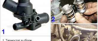
If the engine has problems with the injectors, it is unlikely to be able to start it. Even if the engine starts, its operation will be extremely unstable. This applies to all types of nozzles, and DELPHI devices are no exception. As a rule, motorists do not waste time repairing them. They just buy new ones. But there are situations when you can refrain from buying an expensive DELPHI nozzle. And, moreover, it is reasonable to repair the device yourself. Let's figure out how this is done.
- 2 Gasoline and diesel injectors
2.1 Operating principle and design
- 4.1 Part dismantling sequence
- 6.1 Video: changing the check valve according to all the rules
Where are DELPHI injectors used?
DELPHI injectors are used on any engine with forced fuel injection. It can be either gasoline or diesel fuel. The task of injectors in engines is simple: atomizing fuel in the combustion chambers of the engine.
Appearance of DELPHI diesel injector
Despite the fact that the function of injectors in different types of engines is the same, there are serious differences in the design of these devices.
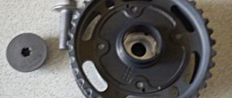
Repair of Delphi injectors
In them, only two components can be repaired - the valve itself and the nozzle. The creators have provided a simple way to disassemble the element and replace worn parts.
Table: markings by car model
| DELPHI injector number | Analogs for DELPHI | Injector number OE | Manufacturer | Car model |
| 28238659 | 28248312 |
28256051
What tools will you need?
In order for the process of removing the injectors from the engine to go quickly, you need to prepare all the necessary tools in advance. Delphi can have different body diameters (depending on the marking), therefore, a set of spanners will have to be selected in accordance with the dimensions of the product on a particular engine:
screwdriver with a thin flat blade;
a can of compressed air;
clean, lint-free cloth;
some used fuel for lubrication.
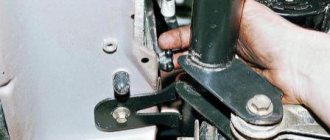
How to remove an injector
Before directly unscrewing these parts, it is necessary to carry out preparatory work. This is necessary so that during dismantling the housing and sensitive atomizer are not damaged.
Video: dismantling procedure
The landing site and the product itself must be cleaned of dirt, fuel and carbon deposits. First, you can clean the dirt with a soft, lint-free cloth, and then begin treatment with compressed air from a tire pump or spray can.
The fuel line from the element must be disconnected with the utmost care so as not to damage the line. With a suitable size key, you can unscrew it slightly from the mounting sockets, one at a time.
After the injectors have been loosened, you can unscrew them from the socket one at a time. Once all the products are dismantled, you will need to wipe the landing site again and close the holes in the motor so that dust cannot get inside.
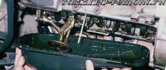
The photo shows how clean the surroundings of the landing site and the product itself should be.
Repair kit for Delphi
For self-repair, you will need to buy a repair kit for the injector. By the way, this is also not a cheap pleasure - a kit with a minimum set of spare parts can cost from 3 thousand rubles. However, the cost of a new part is several times higher, so it is more advisable to spend money on a repair kit than on a new product.
Typically, repair kits for Delphi include several elements:
rubber sealing rings;
copper washer (gasket);
Depending on the needs and purposes of the repair, you can select not a complete set of spare parts, but only those that are really necessary.
Using new parts from the repair kit allows you to quickly replace worn-out elements yourself
Replacing the injector valve
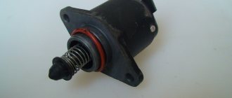
The Delphi valve mechanism is slightly different from similar devices from other manufacturers. It contains a pinwheel as a spray needle. Under the influence of fuel pressure, it either rises or lowers, thereby opening or closing the fuel supply.
The spinner can wear out quickly (since the spray on it is very sensitive to the quality of the fuel). In addition, the seat of the turntable quickly breaks. All this makes replacement a mandatory procedure.
Video: replacement procedure
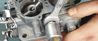
In order to replace the valve mechanism, you must first remove the old one. The valve is unscrewed with two wrenches: one clamps the nozzle body, the other makes amplitude movements. Before installing the new valve in place, it is recommended to slightly moisten it in fuel: this will allow the element to start working faster.
It is recommended to carry out work on a clean surface so that particles of dust and dirt do not get inside the nozzle
Today, injector repairs are carried out by service centers and private workshops. Doing minor work to restore Delphi's functionality with your own hands is only possible when using a repair kit. If the service life is approaching the designated limit, then it is recommended to change the product, since replacing parts will not lead to an optimal result.
Source
Gasoline and diesel injectors
Gasoline injectors are usually classified according to the control systems with which these devices are equipped. Depending on these systems, gasoline injectors are:
- electromagnetic;
The design of the DELPHI electromagnetic gasoline injector cannot be called so simple
- hydromechanical.
Diagram of the hydromechanical injector DELPHI
The main difference between gasoline and diesel injectors is not only in design, but also in the fact that they are not unified. That is, for each engine there is its own, separate type of gasoline injectors. Installing them on another engine simply won’t work.
Another important difference between gasoline injectors is the filter for fine fuel purification. It is a tiny mesh built into the body of the device. In the vast majority of cases, it is the clogging of this mesh that causes the gasoline injector to fail.
Operating principle and device
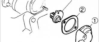
DELPHI diesel injectors are universal; they are installed on almost any car - both cars and trucks. The design of these nozzles can be seen in the figure below.
Schematic diagram of the DELPHI diesel injector
Encoding
Alphanumeric variant of Delphi:
- individual code – C2i of 16 values;
- advanced individual code C3i, of 20 values.
They are endowed with the following characteristics:
- consumption;
- reaction time;
- pressure-dependent operating parameters.
The production process involves recording them in the form of coding, which are applied to the part itself. Their purpose: to provide the ability to accurately coordinate the fuel injection of each cylinder, under conditions of optimal efficiency and differences in calibers of the ECU unit. At the engine assembly stage, the code is entered into the ECU.
Encoding Features
High-quality repair of injectors requires knowledge of the coding characteristics.
The production of identical spare parts is impossible even in nanotechnology factories. In addition, there is a working condition under extremely high pressure. This condition provides for a deviation in the amount of fuel they inject with minimal deviations in shape and size. The result: a decrease in engine efficiency and power, an increase in exhaust gases and noise.
Delphi injector parts
The volume of fuel sprayed is proportional to the injection time and the pressure of the fuel line. Based on this, it is possible to compensate for production deviations by adjusting the duration of the pulse supplied to each unit.
A specific Delphi code is converted based on calculations of fuel flow through the injector at 4-digit pressure. The results are compared with the base operating value to determine the degree of timing pulse correction that is required to target the injection of the proposed amount of fuel. Based on this comparison, a 16- or 20-digit code is determined.
Reprogramming
Whether the injectors are new or after repair, each of them must have a tag with a certain characteristic code. Repair and installation of a component engine requires reprogramming the electronic control unit by entering this code. This manipulation guarantees proper adjustment of the pulses and the supply of a certain amount of fuel in their frequency and duration.
Without reprogramming, the ECU will control this injector based on the previous characteristics. The consequences will be as follows:
- power will decrease;
- the level of exhaust emissions will increase;
- Engine noise will increase.
Reprogramming mechanism
Repairing and replacing an injector requires the presence of a diagnostic device that reads the code and displays it in the ECU. The DS100E and DS150E Delphi devices are recognized by automotive companies as the only ones suitable. They are simple and compact, they are used not only in the diagnosis of diesel engines, but also for all automotive electronic systems. Thanks to these devices, reading and clearing fault codes is an easy and very real task.
Delphi injector disassembled
Purpose of coding in repair
Repairing injectors involves significant changes in their characteristics. After any manipulations, the next mandatory step is to assign new codes to the injector, which will fully reflect the new characteristics.
Creating a new encoding is not an easy process and requires special testing equipment and software. Such a database is available only in authorized workshops.
Signs of a part failure
The main reason for the failure of both diesel and gasoline injectors is low fuel quality. Often such fuel contains highly dispersed impurities or water. All this can damage even the most reliable injectors. Fuel injection will simply be impossible.
Here are the main signs of problems with injectors:
- starting the engine is impossible or extremely difficult;
- engine power decreased sharply;
- the engine is unstable;
- fuel consumption has increased sharply, although the operating mode of the machine has not changed;
- the amount of smoke coming out of the exhaust pipe has increased;
- The operation of the motor is accompanied by characteristic dull pops.
COMMON RAIL DELPHI technology
The English concern DELPHI developed its version of direct injection diesel systems simultaneously with other competitors and received recognition from both European and some Asian manufacturers. The systems are very economical and technologically advanced, inexpensive to produce. Although they differ in increased requirements for the quality of fuel and repair shop, since the components are sensitive to the slightest dirt, even invisible to the human eye. For this reason, the first generations of fuel injection pump systems had a tendency to self-destruct, but later became more reliable.
High Pressure Pumps COMMON RAIL type DELPHI
Type DFP1
The DELPHI DFP1 system belongs to the first generation of DELPHI diesel systems equipped with COMMON RAIL type equipment. The design of the high-pressure pump with a cam mechanism that drives radially located pumping elements follows the architecture of previous generations of pumps for atmospheric rotary engines DPC and EPIC. The pump is driven by a belt or chain. The drive shaft and rotor-type cam mechanism are made as one unit, which caused the main problem of this type of pump - leakage through the seals. In order to smoothly supply fuel under pressure, two fuel compression zones are separated from each other at an angle of 45 degrees. The four-cam camshaft is structurally identical to the traditional DELPHI pump. But unlike it, the pump now does not determine the injection time and flow level, so the compression phase is extended in order to reduce noise and vibration.
The pump consists of a Transfer Pump, whose task is to supply fuel to the injection pump from the fuel tank through the fuel filter under a pressure of 6 bar. The transmission pump also rotates under the action of the camshaft and consists of an eccentric liner, a plate with two oblong holes - one for fuel inlet and the second for fuel supply, four spring-loaded blades, which are located at an angle of 90 degrees to each other. The principle of operation of the Transfer Pump is that the blades, rotating counterclockwise, capture fuel from the open hole on the side of the tank into the cavity between the ring and the shaft. As the shaft rotates, the hole closes and the cavity is completely filled with fuel, which is then transferred to the opening hole in the high-pressure area. And so on through the cycle. Fuel enters the transmission pump from the filter under the influence of negative pressure, and in the pump itself the pressure changes upward as the injection pump shaft rotates. However, it cannot increase more than 6 bar, since a special mechanical valve-regulator (PLV - Pressure Limiter Valve) drains excess fuel back to the inlet of the Transfer Pump.
The amount of fuel supplied to the high pressure area is controlled by a pressure control valve or IMV valve (Inlet Metering Valve). The valve has two tasks: 1) Control of the pressure that the injection pump creates by regulating the volume of fuel supplied. 2) Monitoring the temperature of the fuel drained into the fuel tank. The valve is located on the low pressure side of the circuit. Fuel is supplied to it through two holes at the end of the valve, which are closed by a mesh filter. The idea of a strainer is to protect both the valve itself and the high-pressure system from residual unfiltered dirt. The valve opens in accordance with the request of the computer (DCU) for a certain pressure level. The higher the duty cycle level supplied by the control unit to the valve, the lower the level of high pressure in the rail and vice versa. When off, the valve is constantly open under the influence of a conical spring, which is stiffer than the internal spring at the rear of the valve. Under the influence of a frequency signal from the ECU with a current level of up to 1.1 Ampere, the valve closes the passage to the injection pump, controlling the pressure. The valve is located on the rear of the fuel injection pump housing.
Also on the back of the injection pump there is a temperature sensor (may not be present on some models, for example Peugeot), which monitors the fuel temperature in the range from -30 to +85 degrees.
A distinctive feature of the DELPHI system is the presence of a Venturi tube on the return line, which creates negative pressure in the system to eliminate sudden changes in high fuel pressure. As a rule, the Venturi tube is located on the fuel injection pump housing, but can be removed separately along with the temperature sensor, as, for example, on a Peugeot car. The operating principle is that there is a narrowing of the channel inside the valve, which stabilizes the fuel flow.
Some variations of this type of injection pump have an additional nozzle on the housing, which is completely independent of the nozzles in the cylinder head and is used when it is necessary to supply fuel and increase the temperature to regenerate the particulate filter.
The area of the pump that compresses fuel under high pressure consists of intake and exhaust valves, pistons and rollers, which are supported by two springs. Under the influence of pressure from the Transfer Pump, the inlet valve opens and fuel enters between the two plungers. The rotating rollers are pressed by cams and the pistons compress the fuel. At this moment, under the influence of hydraulic pressure, the inlet valve closes (as soon as the pressure inside the pump becomes higher than the fuel supply pressure), and the outlet valve opens, transferring the fuel flow to the ramp. The ball valve opens as soon as the pressure inside the pump becomes greater than the pressure in the rail, releasing fuel.
The pumps are lubricated and cooled by diesel fuel. For normal operation, the pump must pass 50 liters of fuel per hour. In one and a half revolutions, the injection pump should create a pressure of 200 bar. Depending on the manufacturer, the injection pump may have 2, 3 or 4 plungers, and develop a maximum pressure of up to 1400 or 1600 bar.
Type DFP3
Unlike DFP1, the new generation of the DELPHI DFP3 system has a shaft with an eccentric, which are connected to rods. Rotating under the influence of the drive shaft, the eccentric acts on the rods, which compress the fuel. The pump can be modified with two plungers, which are separated at an angle of 180 degrees, or with three plungers, located at an angle of 120 degrees. The main differences between the DFP3 system and the previous generation are the use of an eccentric, a modified shape of the transmission shaft, the number of plungers, the use of roller bearings instead of plain bearings, greater productivity per revolution, higher shaft speed, smaller dimensions, options without a transmission pump, more power and less noise. The transfer pump is located not inside, but on the outside of the pump housing. If available, a valve is used to control the fuel transferred to the compression area.
The operating principle of the Transfer Valve is the same as that of the previous generation pump; they are similar in appearance, but they are not interchangeable, since they have different calibrations and are produced by different manufacturers. The maximum valve solenoid control current is 1.3 Amps. The task of the temperature sensor is the same as for DFP1. The mechanical pressure control valve PLV (Pressure Limiter Valve) regulates the pressure at 1850 - 2500 bar. In the event of a problem with the IMV valve or a malfunction with the fuel supply through the injectors, the valve circulates fuel in a circle to the pump inlet. On some systems, if there is a pressure regulator on the rail, this valve is not present in the injection pump (for example, DFP3.4. - Mercedes). A Venturi-type valve can be located both inside and outside the injection pump on the discharge side into the return line, and serves to eliminate pressure fluctuations in the rail through negative pressure in the return line. This valve is not available on systems with Direct Acting injectors. The nozzle for regenerating the particulate filter is identical to the previous generation.
The pump is driven by a belt, chain, or cross-clutch drive that rotates a shaft with eccentrics that push a plunger and spring, compressing the fuel, which is delivered to a high-pressure area through a mechanical bypass valve. The inlet valve opens under the influence of vacuum, which is created when the plunger moves downward under the action of the return spring. As the plunger moves upward, the fuel is compressed, closing the inlet valve and opening the outlet valve to force compressed fuel into the rail.
There are several varieties of the DFP3 system (3.1, 3.2, 3.3, 3.4), which differ in shape, number of plungers, drive and supply pressure from 1600 to 2000 bar.
Type DFP4
The DELHPI DFP4 system is developed on the basis of DFP3 and is intended for use on commercial vehicle engines.
The pump has two plungers separated at an angle of 180 degrees. The design differs from the previous version in the presence of a DLC coating on the intake valve, the use of a ceramic ball in the exhaust valve, the presence of an eccentric with slots, and fuel cooling of the front and rear sliding bearings. In an architecture where there is an HPV (High Pressure Valve) valve that regulates the pressure on the ramp, a mechanical pressure limiter valve may be absent from the injection pump as unnecessary (for example, engines for JCB). The DFP4 system also has a Venturi, which can be either inside or outside the pump. DPF systems have an injector to supply fuel at 6 bar pressure to the DPF system for regeneration. Pumps of type DFP4.2 rotate counterclockwise, and pumps of type DFP4.4 rotate clockwise. Injection pumps of this type can develop a maximum pressure of up to 2000 bar.
Type DFP6
DELPHI DFP6 type pumps belong to the third generation of DELPHI fuel systems for COMMON RAIL. Injection pumps of this type inherited the architecture of the previous generation with cams and rollers. However, they are smaller, lighter in weight, less noisy, more efficient in performance, and produce higher pressure. The main technical differences are the presence of one plunger and a push-pull compression system during one revolution of the shaft, as well as the presence of a combined roller and piston. Also, these pumps do not have a temperature sensor, since it is located in the low pressure area. In addition, DFP6 pumps do not have a Transfer Pump. Fuel is supplied to the injection pump using a submersible electric pump in the tank, which delivers fuel to the injection pump under a pressure of 6 (-\+1) bar. The IMV valve on the pump controls the amount of fuel that is supplied for compression and at the same time regulates the temperature of the fuel. The DCU controls the valve using a duty cycle of 200-800 Hz and a current of 1.3 Amps. On Peugeot, Citroen and Ford DW10F cars, the temperature sensor is located between the filter and the injection pump.
Another difference of the DFP6 system is the absence of a mechanical pressure limiter valve in the pump. This function is performed by either a pressure control valve (HPV) or a mechanical limiting valve (PLV) on the rail. The Venturi tube is located on Volkswagen pumps with an outlet for the diesel particulate filter injector.
On modern cars, fuel injection pumps of this generation can be driven by a belt or gear. The shaft rotates a double eccentric along which the roller moves, repeating its shape. The roller presses on the plunger, which is returned back by a spring. The plunger compresses the fuel according to the same principle as in previous generation pumps. DFP6.1 injection pumps create pressure from 1800 to 2000 bar, DFP6.1E pumps create only 2000 bar pressure.
DELPHI (DFI) system injectors
Injectors DFI1.1 - DFI1.4
Fuel injectors of type DELPHI DFI 1.1 - 1.4 have the following elements: - Injector nozzle and needle; — Nozzle body with inlet and return hole; — Valve coil integrated inside the body; — Fuel inlet filter; — Adaptive bar with control capacity and calibrated holes for needle control; — Valve in the nozzle body; — Sealing washer;
The maximum pressure that is used in the system with DFI 1.1-1.4 injectors is up to 1800 bar and the force that lifts the injector needle is very high. This means that it is not possible to control the injector needle directly with the solenoid valve, as this requires a very high current. The saturation time of this current intensity is relatively long, and the needle must be controlled in much shorter periods of time. In addition, this current level requires increased DCU power and may overheat the injector. Thus, the needle inside the nozzle is controlled by a valve that controls the pressure in a container located directly above the needle. At the beginning of injection, when the needle should rise and open the holes in the lower part of the nozzle, the valve opens and the contents of the container are drained into the return line. To close the needle, the valve creates pressure inside the container and pushes the needle down. The task of the valve in the nozzle is to consume the least amount of energy for its operation. Therefore, it is lightweight and the valve moves with minimal effort. In the closed position the valve must be in hydraulic equilibrium. This balance is achieved by using identical container geometry so that the pressure on the valve is the same in all places. Thus, to hold the valve in place, you can use a very soft spring, which can be easily pressed, applying a load to the valve, and so raise the needle. Problems with dirty fuel have led to changes in the injector design to control temperature and the use of a carbon coating (DLC - Diamond Like Carbon) on the internal surfaces of the valve. The adapter sleeve is located at the valve mounting location. It connects the control chamber with three nozzles: supply for injection, return from the control chamber and inlet for filling the chamber with fuel.
The pressure distribution in the nozzle can be divided into several stages:
— Before filling the adaptive bushing, fuel under high pressure is supplied inside the injector, first filling the channel to the control chamber, then the channel to the fuel gallery of the injector, then supplied to the channel of the valve chamber; — Under high pressure, fuel fills the control chamber, the adaptive bushing and the spiral grooves in the needle.
Once this stage is reached, the fuel inside the injector becomes balanced and the injector itself is closed. The fuel pressure in the recesses on both sides of the valve body inside the injector is at the same level at rest. When the DCU activates the coil, the valve opens. If the valve force becomes stronger than the spring force. Opening the valve allows fuel to flow back, lowering the pressure in the valve chamber, then in the channel to the fuel gallery and then in the channel to the control chamber. But the needle itself is in place, because the pressure does not drop in the control chamber itself. The needle movement begins when the pressure drop extends into the control chamber and a pressure imbalance appears at both ends of the valve. As the pressure at the end of the needle becomes higher than in the control chamber, the needle moves upward, opening the way for fuel through the fuel gallery into the combustion chamber. At the same time, passing through the nozzle at the end of the gallery, the pressure drops compared to the pressure in the ramp. At maximum pressure in the rail, the pressure loss after the fuel gallery will be about 100 bar. When the DCU removes current from the valve coil, its force becomes weaker than the spring force and it pushes the valve back, closing the valve. The pressure inside the nozzle increases, but the needle does not close the nozzle, because in order to close it, it is necessary to create a pressure difference at different ends of the needle. This difference is created by the loss of pressure in the channel to the fuel gallery in relation to the control chamber, where the pressure is the same as in the ramp. As soon as the pressure in the control chamber becomes greater than at the end of the needle, the needle moves down and closes.
The line for draining fuel back into the tank is attached to the nozzle either through a rubber nipple with a metal tube, or through a special plastic adapter. Injectors of this type can produce from two to five individual openings during one injection cycle: Separate pilot, Close pilot, Preliminary, Main, Close post injection, Post injection, Auxiliary post injection. In addition, injectors of this type have a feature such as draining fuel into the return line in an emergency (except for models with an HPV valve). This is necessary if you suddenly take your foot off the gas pedal or if an error code occurs that requires a sharp decrease in rail pressure. To do this, the injector coil receives a pulse from the DCU, which is enough to lift the valve and connect the fuel in the rail to the return line, but not enough to raise the needle and allow fuel to enter the engine. Such control is only possible if the time between the beginning of the valve movement and the beginning of the opening of the needle is precisely known. This time depends on the physical properties of each specific injector and the degree of wear. Therefore, the program in the control unit needs to know exactly the physical state of each injector. This is achieved by calibrating the injectors at the factory and assigning each injector an individual code. DELPHI uses two types of injector calibration: -C2I (Correction Individual Injector). Use hexadecimal code (16 characters).
-C3I (Improved Induvidual Injector Correction). More accurate calibration of injectors in production and the use of an alphanumeric code (20 characters). The code is entered into the DCU memory when replacing an injector with a new one, or the code from old injectors is entered into a new unit when replacing the DCU using a scanner. Based on the calibration data that is encoded in the code, the control unit makes corrections for each injector.
Injectors DFI1.5/1.5.2
DELPHI DFI 1.5 type injectors were designed to perform the following tasks: - Support Euro 5 standard;
— Increasing injection efficiency; — Supports up to 7 openings during injection; — Better protection from dirt; — Increased flow stability during injection; DFI 1.5 injectors consist of a nozzle with a needle, an injector body with an inlet with a filter and a return outlet, an electrical connector at the top of the injector, an adapter plate (CVA) with calibrated holes for controlling the needle and a combination valve, as well as a mounting washer. Depending on the generation, the injector can operate at a pressure of 2000 bar. Because at this pressure it is impossible to control the needle directly with an electromagnetic activator, since the applied force would be too powerful, which would heat up the control unit and the nozzle itself, and the reaction time would be too slow. Therefore, the opening of the needle is controlled through a control chamber, where the fuel is drained into the return line to open the needle and the pressure in the chamber is restored if it is necessary to close the needle. Main differences from the first generation: Special varnish coating of the needle and its seat, the angle of which has been changed to 60 degrees, a reduced angle between the holes in the nozzle, an increased diameter of the inlet channel, a combined adaptive plate with a valve, increased spring return force, a new type of connectors (unified with DFI3), increased diameter from 17 to 19 mm. Also, this type of injector uses two types of connectors. The same as on the old generation (Peugeot, Citroen, Ford), as well as a new V-shaped one with asymmetrical pins. The return connection system is similar to DFI 1.1, and the C3I method is used for calibration.
Type DELPHI DFI 1.5.2 is designed to support Euro 6 standard and pressures up to 2200 bar. It uses a more efficient coil, an even stronger valve return spring, an improved CVA block design, and maintains pressure inside the injector at 3000 Newtons when the cap is screwed on. A plastic adapter is used to drain into the return line. The injector is calibrated using the C3I method with a 20-digit code.
DFI1.20 injectors
DELPHI DFI 1.20 injectors have been developed to support the Euro 6 environmental class and operate at a maximum pressure of 2200 bar. The injector design elements are identical to previous generations. Differences include the use of a new AK type electrical connector, a new return connector with positive pressure of 6 bar, a new improved coil type, a narrower atomizer needle and a modified internal shape of the needle channel, micron level tolerances and a reinforced spring up to 33 Nm and a modified CVA design module. Since in the new nozzle the return flow is supplied under a pressure of 6 bar, the tip of the drain hole is made of metal and has a rubber ring. The operating principle of this nozzle is similar to previous generations. In order to more accurately calibrate the injector, the C3I coding algorithm was used for this, and for Volkswagen cars with 1600cc and 2000cc engines, since the end of 2014, a new, more accurate Improved C3I calibration technology began to be used so that the control unit understands how the injectors behave under ultra-high pressure 2000-2200 bar. In this case, a 20-digit code is also used, and it is visually impossible to understand how the nozzle is calibrated. This can only be determined by the part number. During the calibration procedure, the DELPHI DS150/DS350 or AUTOCOM scanner can determine the type of calibration by the entered number.
DFI2.3 injectors
DELPHI DFI 2.3 type injectors are designed as version 1.3, but with a higher fuel flow to work on commercial engines and large-sized units. The injector consists of an atomizer with a needle, a main body with holes for fuel supply with a mesh filter and for draining into the return line, an integrated coil, an electrical connector, an adaptive bushing with a control chamber and calibrated holes for controlling the needle, valve and gasket. Depending on the generation, the injector operates at a maximum pressure of 1600 bar. Since this is a relatively high pressure, it is not possible to control the needle directly with a solenoid due to the very high current required and the impossibility of synchronizing multiple openings very quickly. Therefore, the hydraulic control method used is the same as that of previous generations of injectors with a control chamber. The injectors are widely used on engines of trucks and construction equipment, for example, JCB, with an environmental class higher than Euro 3. The injector drain channel has a special LP connector. Injectors are calibrated using both the C2I and C3I methods.
DFI2.5 HPC injectors
DELPHI DFI 2.5/2.5 HPC injectors are a further continuation of the development of COMMON RAIL diesel engine technology for commercial vehicles. The 2.5 generation injector supports operation in environmental class up to Euro 5 at a maximum pressure of 2000 bar. In addition, the nozzle has improved injection characteristics - IRCF (Injection Rate Coefficient Factor) with the ability to carry out up to 7 openings during one injection cycle with special protection against the penetration of dirt particles into the body. Otherwise, the nozzle has the same elements as the previous generation. This type of injector uses a special new coating for the needle and its seat, which improves injection dynamics, the needle seat angle is changed to 60 degrees, and the needle diameter is increased. The angle between the nozzle holes is reduced, and the inlet holes are enlarged to allow a larger volume of fuel to pass through. The load on the return spring is 28 N. The diameter of the nozzle itself has been increased from 17mm to 19mm.
The nozzle can be equipped with two types of connectors. For example, on JCB and DAEDONG equipment this is a similar connector with DFI 1.1 -1.3, while on other brands the injectors may have connectors similar to those of the DFI3 type. The backflow connector can be metal with a rubber nipple or plastic. The operating principle of this type of injector is the same as that of type 1.5, and calibration at the factory is carried out according to the C3I principle with a 20-digit code. DFI 2.5 HPI injectors are designed for large engines. They operate on units for environmental class above Euro 4 and at a maximum pressure of 2000 bar. They are distinguished by a large body diameter (26mm and 28mm) and a large diameter of the inlet holes. Another feature of the nozzle is a special connector. Since the injector is located deep in the cylinder head, only the wire connected to the engine's central wiring harness is exposed. The connector itself penetrates deep into the engine and connects to the injector in the middle of its body, which is very unusual compared to other types of injectors. But this is due to the use of this nozzle on engines with a large physical size. Therefore, the return flow channel is also located in the middle of the nozzle and is connected to the internal channels in the block head.
DFI3 injectors
DELPHI DFI 3B injectors differ from other generations by the presence of a direct-acting piezo element, when the effect of changing its crystal size under the influence of voltage is used to directly control the needle instead of the electro-hydraulic principle. This technology allows the injector to be opened for a period of 100 microseconds, which allows 7 or more openings to be added during the full injection cycle. The new generation of injectors does not have a return drain, which allows the injector energy not to be wasted on transferring fuel to the tank. Another achievement is the ability to achieve amazing injection stability throughout the entire engine operating life. In addition, with a piezo injector, the process of atomization of the mixture in the combustion chamber is faster, and the injection pressure is higher. The rapid movement of the needle allows you to control and save fuel that enters the engine as the needle moves up or down, controlling the quality of the spray both at the beginning and at the end of injection. This technology made it possible to reduce soot and NOX emissions by 30%, made it possible to reduce particulate filters and greatly reduce engine noise. A new generation connector is used to connect the injector to the control cable.
When the injector is under pressure, all the compressed fuel is forced into it. Under the influence of a voltage of 200 Volts, the piezoelectric element in a balanced system is in a compressed state. Physical compression reduces the volume of fuel inside the injector. The pressure between the piston and the spring drops and the internal pressure balance is disrupted. Now the pressure at the spring is lower than in the piston. This allows the spring to rise to begin injection until the very end, at which point all the compressed fuel enters the combustion chamber until the 200-volt voltage supply is cut off again. Injector correction is carried out using a 24-digit code.
When working with this type of injector, care must be taken to never remove the electrical connector while the engine is running, since we cannot predict in which position the needle will remain, and it may remain open. Also, under no circumstances should the polarity of the connector be changed. Since the peak voltage in the injector circuit can exceed 250 volts, safety precautions must be followed when working with them. Do not touch the exposed contacts of the injector with your hands after removing the connector, since an electrical charge may remain in it. That is why DELPHI offers a set of caps YDT499, which are put on the injector immediately after removing the connector.
Fuel Rails DELPHI COMMON RAIL
The task of the fuel rail or ramp is to accumulate fuel under high pressure, which arrives there from the injection pump and further distributes it among the injectors. The fuel rail consists of a housing, fuel pressure sensor, inlet and outlet ports, high pressure activator HPV and pressure limiting valve PLV. DELPHI type ramps can be cylindrical or spherical, such as those found on the Ford Lynx and Renault K9K. The advantage of this design is that the ramp has a small volume, it is lightweight and inexpensive to manufacture, but all the tubes have different lengths to the injectors. Therefore, this type can only be used on small engines, since the tube from the rack to the injectors should not be too long, as this will affect pressure stability. If the ramp has a smaller physical volume, then it is faster to fill and therefore the increase and decrease in pressure can be quickly adjusted. Therefore, the choice of rack type for designers is a compromise between the quick controllability of the system and the hydraulic stability within it.
At the point where the outlet tubes are attached to the injectors, the rails have a narrowing of the channel, which makes it possible to avoid pressure fluctuations and better injection controllability. On the latest generations of racks, narrowing of the channel is used not at the end of the pipe at the place where the fuel pipe is attached, but on the inside of the channel, starting from the main line.
Fuel pressure sensor
Traditionally, the sensor is located on the fuel rail. The principle of its operation is the deformation of a metal spring. The membrane contains a piezo element, which changes its resistance in accordance with the deformation of the membrane. The pressure level is equal to the membrane deformation level. The resistance level is converted into an output signal to the control unit. Early versions of the sensors had a gasket between the valve nose and the ramp body, but recently an option has been used where the sensor touches the ramp directly. When fixed, its thread is deformed, therefore, as a rule, these sensors are not changed separately from the ramp.
Rail Pressure Control Valve (HPV)
The high pressure control valve is located in the fuel rail and, together with the IMV flow control valve, controls high pressure in the system. The valve's task is to reduce the pressure in the rail, draining part of the fuel into the return line to the tank. Therefore, on systems with an HPV sensor, nozzle return control is not used. Another function of the valve is to eliminate peak pressure fluctuations. Another role is emergency, or a sharp decrease in pressure in the system due to a malfunction of the rack or nozzle. The engine ECU controls the valve when it is necessary to quickly warm up the engine at the start in cold weather, without controlling the IMV valve. It is also actively used when the IMV valve fails. If it malfunctions, an error code appears. At the same time, in the event of a break in its own electrical circuit, the valve must create the pressure necessary to start the engine.
The valve consists of a piston that is fully opened and closed by a spring, an electrical connector, a valve coil that is controlled by current, a rod attached to the piston with a ball mechanism, a cylindrical strainer with a central inlet and two outlets. In the absence of pressure, the valve is in a constantly open state and closes to create the pressure necessary for idling, and then in accordance with the specified duty cycle. The duty cycle of the signal depends on the engine speed, the required rail pressure, the actual rail pressure and the fuel temperature. It is also used to completely stop the engine.
Mechanical pressure limiter (PLV)
A mechanical fuel pressure limiter is optional for DFP1 and DFP3 systems. The valve mechanically opens at a pressure level of 2450-2640 bar and drains fuel into the return line to the tank. The valve can be either on the injection pump or on the ramp (always if there is no HPV valve). The valve's task is to protect the system in emergency situations.
Cylinder pressure sensor
Some Euro 6 fuel systems may use in-cylinder pressure sensors. They are bolted to the cylinder block near each injector (Daimler) or integrated into the glow plugs (VW). The sensor's task is to provide information about the actual pressure in each cylinder. It plays the role of a thermodynamic indicator to monitor the combustion process and effectively control the closed cycle. Its signal affects injection control and engine rotation.
List of cars that use the COMMON RAIL system type DELPHI: ALPHA ROMEO : 4C BMW : 3 SERIES GT CHEVROLET : CORVETTE STINGRAY CITROEN : C3 1.4 HDI, C3 PICASSO FERRARI : LA FERRARI FORD : TRANSIT, FOCUS 1.8 Tdci, MONDEO 2.0 TDCI, TRANSIT 2.4 EU3 HYUNDAI : TERRACAN, TRAJET, I20, I30 INFINITI : Q50 JOHN-DEERE : 6125 H KIA : CARNIVAL, BONGO LAND ROVER : FREELANDER td5 MERCEDES BENZ : CLA, E CLASS NISSAN : NOTE OPEL : ZAFIRA PEUGEOT : 2008 P ORSCHE: 911 GT RENAULT : CLIO, CAPTUR, KANGOO, SCENIC ROLLS-ROYCE : WRAITH SSANYONG : REXTON/KYRON/ACTYON/RODIUS/STAVIC CRDI SEAT : LEON SC SKODA : OCTAVIA VOLVO : V60 VOLVO\DAF : F105 VOLVO TRUCK :FH12 420HP /460HP, V 60
Replacing the injector valve
This is the most acceptable and effective measure aimed at completely eliminating problems and defects of a given unit. But keep in mind: it is better that the replacement of valves on Delphi injectors is carried out at a service station and exclusively by experienced professionals. If you do not want to use the services of auto mechanics, then you can try to perform all the manipulations yourself.
Typically, this process consists of the following steps:
- Removing the nozzle.
- Disassembling the unit into components.
- Placing all elements in a bath with diesel fuel. Sterility is paramount. Further work is carried out wearing gloves!
- We remove the old valve.
- We assemble the nozzle, installing new spare parts.
- We wipe the wells in the motor to prevent dirt and dust from entering the repaired unit.
- We install the nozzle.
Please note: immediately after repair the motor will run unevenly. Usually this defect lasts no more than 30 - 40 minutes. Then, the engine will begin to function properly.
Replacing a Delphi injector valve yourself is a complex process that requires a significant number of tools for assembling and disassembling the engine. The slightest mistake - and backlashes, gaps and other defects will appear. Therefore, it is easier to immediately turn to professionals.
Source autexpert.ru
Injectors are a relatively new element of fuel systems. Their main purpose is to ensure fuel dosing and inject fuel into the operating cylinders of the engine. French-made Delphi elements have proven themselves to be good, but their reputation is slightly tarnished by the fact that car enthusiasts periodically have to carry out minor repairs with their own hands.
Important points
There are several nuances that must be taken into account when disassembling the nozzle. If this is not done, the simplest valve replacement procedure can cause a lot of problems for the driver:
- the nozzle should be disassembled on a flat table that is well lit, and the light source should not be behind the car owner, but in front of him;
- You need to lay a clean sheet of paper or a white napkin on the table (on it the small parts of the nozzle will be clearly visible and will not roll out);
DELPHI injector disassembled on a blank sheet of paper
Medical tweezers that are convenient for removing return springs from injector valves
Even a novice car owner can easily remove the injector and replace the check valve on it. All you need is a DELPHI branded repair kit and a little patience. As for experienced car owners, repairing one injector takes them no more than 30 minutes.
How to repair Delphi Common Rail diesel injectors. Disassembly, cleaning, valve replacement
Delphi injectors have sufficient power and economy, but at the same time they have a big drawback in the form of fear of dirt or debris that may be in the fuel system.
On a car, this can manifest itself in different ways: in winter it is poor starting of the car, and at above-zero temperatures it is an error at high speeds, as well as engine tripping.
All such symptoms are accompanied by a decrease in pressure in the fuel rail, increased fuel consumption, and the appearance of black smoke in the car, and this in turn leads to contamination of the particulate filter or USR valve.
What to do? The fact is that in these nozzles a multiplier is responsible for the return, which acts as a kind of regulator; when the surface of this valve gets damaged, the nozzle begins to drain into the return. The most common problem with all Delphi diesel injectors is loss of pressure. And all because the valves in the injectors either become clogged from low-quality fuel or rust from water in the diesel fuel.
The resource of this multiplier is up to 150 thousand kilometers
, which means that it is necessary to do routine maintenance during such runs with valve replacement, so that one morning you simply cannot start your car.
How to repair a Delphi diesel injector
The essence of restoring the functionality of the Delphi injector is that you need to change the check valve and clean not only the atomizer, but also all disassembled parts of the injector with carb cleaner.
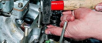
First, you need to clean the outside of the nozzle so that during repairs debris does not get inside the nozzle, and special attention must be paid to the nozzle; when cleaning it, you should not scratch the nozzle of the nozzle, otherwise the nozzle will start pouring fuel incorrectly.
When the nozzle is cleaned, clamp it in a vice, take the 15mm Delphi injectors only have this type of head) and unscrew it counterclockwise. Carefully remove the nut.
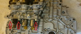
It is very important to remember the order in which you disassembled the injector, if you do not want to later go to diesel specialists with the problem that the injector does not work.
The structure is simple: nut, nozzle, needle, plunger, spacer, multiplier, spring and housing. All elements of the nozzle must be blown out and carefully washed, except for the body itself; for flushing and cleaning, it is best to use a synthetic carburetor cleaner.
After applying the cleaner, the nozzle also needs to be blown out, so it is advisable to have a compressor on hand.
We replace the old valve with a new one and assemble the nozzle in the same sequence as we disassembled. It is best to clean the carbon deposit nut with a drill bit. We assemble the nozzle and apply thread sealant or sealant, the main thing is to apply it only to the threads without touching the inside of the nozzle, otherwise the multiplier may be damaged.