The torque from the differential side gears to the drive wheels is transmitted by shafts called axle shafts. In addition to torque, axle shafts can be loaded with bending moments from forces acting on the drive wheel. Such forces are the reaction of the road F from the vertical load falling on wheel 1 (Fig. a), the traction force P (or the braking force during braking), the lateral force T that occurs when turning and skidding. Depending on the installation method, the axle shafts can be completely or partially unloaded from bending moments arising under the action of the listed forces at distances c and z, respectively.
The fully unloaded axle shaft 4 (Fig. b) is installed with its inner end on splines in the differential side gear, the housing of which rests on bearings, and is connected to the wheel hub with the outer end using a flange. The hub 5 with the wheel is mounted on two bearings 2 on the bridge beam 3. With this installation, the axle shaft transmits only torque, and all bending moments are perceived through the bearings by the bridge beam, which facilitates the operating conditions of the axle shaft. Fully balanced axle shafts are used on transport wheeled vehicles of medium and heavy load capacity.
Rice. Axle shaft installation diagram
In the drive of the steered drive wheels to the constant velocity joint 19, torque is supplied from the differential by the inner axle shaft 6. The outer axle shaft 23 has a flange, from which the torque is transmitted to the wheel hub 2. The wheel hub is mounted on a steering axle 22 using two tapered roller bearings 1, which transmit all bending moments from the above forces to the axle. The axle with its body 4 is mounted on pins 21 with bearings 5, rigidly mounted on the tips of the bridge beam 7. Axle shafts 6 and 23 are loaded only with torque.
If the axle shaft with its outer end directly rests on bearings 2 (see a) installed in the bridge beam, then it receives bending moments from all the forces listed above and, in addition, transmits torque to the drive wheel. Axle shafts of this type are called semi-balanced. They are usually used only on passenger cars. On all-wheel drive wheeled vehicles, fully balanced axle shafts are used almost exclusively.
On high-speed tracked vehicles, the turning mechanisms used to control movement are included in the transmission, since torque is transmitted through them from the engine to the drive wheels.
Many drivers ask the question: “What is a car axle shaft?” This is a shaft that transmits rotation from the car engine to its drive wheels. The more commonly used name for the axle shaft is the drive shaft.
- What is a car axle shaft used for and where is it located?
- The design and principle of operation of the axle shaft in a car
- Types of axle shafts Semi-weighted
- Unloaded
We recommend: What are the criteria for choosing wipers?
Interesting ! The undisputed leader in the production of spare parts for cars, especially drive shafts, is the German company GKN(LOBRO).
What is a car axle shaft used for and where is it located?
Let's look at what the axle shaft is for and where it is located. The axle shaft or drive axle shaft provides moving contact between the engine and the drive wheels, transmits forces, maintains the ability to turn the wheels, and allows the suspension to move smoothly with minimal vibration.
The main purpose of a car's axle shafts is to absorb the force of gravity that falls on the wheel due to traction and braking forces. It accounts for bending moments and the consequences of lateral forces during skids.
The axle shaft design has two hinges that ensure uniform transmission of force in any position of the suspension and steering parts. This significantly dampens vibration of the steering column and prevents the car from moving jerkily.
Important! If the drive shaft breaks, the vehicle may become partially or completely uncontrollable.
The design and principle of operation of the axle shaft in a car
The design of the axle shaft is such that the effect of power transmission will be maximum at any position of the wheels. This design consists of three parts:
- external constant velocity joint (CV joint);
- shaft;
- internal CV joint.
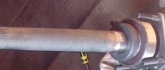
A shaft is, roughly speaking, a piece of pipe of a certain length to which adapters for installing CV joints are welded. To prevent these elements from scrolling, they are equipped with special slots. At the end of the adapter, the shaft is secured with a retaining ring, otherwise the shaft may jump out of the CV joint when moving.
In passenger cars, the front drive wheel is driven by external and internal constant velocity joints connected by an axle shaft.
The use of two hinges in the drive is caused by the independent suspension of the front wheels.
Internal hinges are responsible for the movement of the wheels during vertical suspension strokes
, and
external ones - for turning the wheels relative to the vertical axis
, which is necessary when changing direction.
Types of axle shafts
Depending on the device, the types of car axle shafts are divided into fully unloaded axle shafts or partially unloaded axles, depending on the bending moments affecting it.
We recommend: Why do we need engine oil thickeners?
Semi-unloaded
The semi-balanced axle shaft is installed mainly on passenger cars. In this type of design, the bearing is located between the axle shaft itself and its casing; the axle shaft is attached directly to the wheel hub.
This leads to the appearance of bending moments on the axle shaft. In cars with front-wheel drive, the axle shaft has a different structure.
Did you know? In 1929, front-wheel drive was first used on a car.
Unloaded
The balanced axle shaft is used mainly on trucks and buses. Such a part will be freely installed inside the bridge, and the wheel hub will rest on the bridge beam with two bearings.
The entire force of the bending moment in such a device is taken by the bearings, and the axle shaft only transmits torque.
Main causes of axle shaft failure
The axle shafts bear heavy loads when the vehicle moves over uneven ground and potholes, as well as along broken roads. The cause of failure may be wear of bearings and seals. The oil heats up as it moves and washes out the bearing lubricant through defects in the seals. Another reason could be a defective retaining ring. If they jam, the axle shaft may break.
Attention! If your car leaves a trail of oil stains, the first thing to do is inspect the oil seal.
On cars with front-wheel drive, CV joint boots tear, which also affects the hinges. With a long service life, the axle shaft may become loose and break the splines. Breaks of the axle shafts themselves occur in the middle or at the fastening points. Problems can arise suddenly and accidentally, if you remember the condition of the roads. But they can also be natural in case of careless attitude towards the car, with low quality of repairs and replacement parts.
Subscribe to our feeds on social networks such as Facebook, Vkontakte, Instagram, Pinterest, Yandex Zen, Twitter and Telegram: all the most interesting automotive events collected in one place.
Main types of axle shafts
Depending on the design, the axle shaft can be fully or partially unloaded from the bending moments acting on it.
Balanced axle shaft
more typical for heavy-duty vehicles, including buses. In the drawing, such an axle shaft will look like a part freely installed inside the bridge, and the wheel hub will rest on the bridge beam using two bearings. In this design, the axle shaft transmits exclusively torque, since the entire bending force is absorbed by the bearings.
We recommend: Choosing oil for two-stroke engines
Types of axle shafts
Half-loaded axle shaft
in the vast majority of cases it is installed on passenger cars and light trucks. The design of this type of axle shaft is different in that it has a bearing between the axle shaft itself and its casing, and the axle shaft is attached directly to the wheel hub. For this reason, bending moments periodically occur on the arm, which affect the axle shafts in the vertical and horizontal planes.
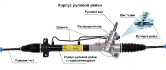
On front-wheel drive vehicles, axle shafts of a slightly different design are installed to transmit torque from the gearbox to the wheels. Such a drive shaft consists of an axle, internal and external CV joints.
Drive shaft design of a front-wheel drive vehicle.
Purpose of the axle shaft
All drivers know what a car axle shaft is. The main function of this part is to transmit torque to the drive wheels, support the ability to turn the wheels at speed, and also ensure smooth movement of the vehicle in the presence of minor vibrations.
As a rule, the drive shaft is installed on non-steering wheels on vehicles with dependent suspension. In the case of an independent suspension, this function is taken over by the cardan transmission, and on the unsteered (for passenger cars these are the rear) wheels, a hinge mechanism of unequal angular velocities is installed, and on the steered front wheels, a constant velocity joint copes with this task.
In general terms, we can describe what axle shafts are intended for, as the ability to perceive the action of various forces generated as a result of the movement of the car. Note that in absolute terms these are very serious loads, so increased demands are placed on the design of the axle shafts and the material used to make them.
The presence of two hinges in the drive shaft, located at both ends of the part, can significantly reduce vibrations transmitted to the steering column, preventing jerky movement of the machine.
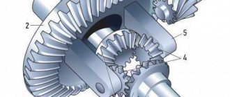
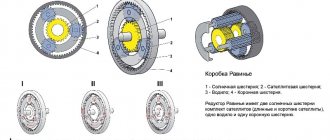
How does the differential work?
Schematic diagram of the differential
The unit operates as a planetary gearbox. The basic structure of the differential: the gears of the axle shafts (5) and satellites (4) are located in the cup (3). The cup (housing) is rigidly connected to the driven gear (2), which receives torque from the main gear drive gear (1). The housing transmits rotation through satellites to axle shafts that rotate the drive wheels. Different angular velocities are provided due to the operation of the satellites. The amount of torque remains unchanged.
The design and principle of operation of the axle shaft in a car
The design of the axle shaft is such that the effect of power transmission will be maximum at any position of the wheels. This design consists of three parts: an external constant velocity joint (CV joint); shaft; internal CV joint. A shaft is, roughly speaking, a piece of pipe of a certain length to which adapters for installing CV joints are welded. To prevent these elements from scrolling, they are equipped with special slots.
At the end of the adapter, the shaft is secured with a retaining ring, otherwise the shaft may jump out of the CV joint when moving. In passenger cars, the front drive wheel is driven by external and internal constant velocity joints connected by an axle shaft. The use of two hinges in the drive is caused by the independent suspension of the front wheels. The internal hinges are responsible for the movement of the wheels during vertical suspension strokes, and the external hinges are responsible for turning the wheels relative to the vertical axis, which is necessary when changing
Causes of axle shaft failure
During the operation of the vehicle, the axle shaft constantly operates under quite serious loads, including:
- bending moment, which appears due to the effect of gravity on the car;
- tangential reaction that occurs when the vehicle starts to move and brakes;
- lateral force due to car skidding;
- lateral loads arising from the influence of strong cross winds.
Axle shafts experience almost extreme loads when the vehicle moves on dirt roads, as well as on broken highways.
A broken axle shaft leads to a complete or partial loss of vehicle control, so proper, thorough and timely care is of great importance.
During operation of the drive axle, it is necessary to periodically check the condition of the bearings located on the axle shafts. Their long-lasting performance can be achieved by providing complete protection against the penetration of dirt and liquids.
Purpose and types of axle shafts | Transmission
The torque from the differential side gears to the drive wheels is transmitted by shafts called axle shafts. In addition to torque, axle shafts can be loaded with bending moments from forces acting on the drive wheel. Such forces are the reaction of the road F from the vertical load falling on wheel 1 (Fig.
a), traction force P (or braking force during braking), lateral force T, which occurs when turning and skidding. Depending on the installation method, the axle shafts can be completely or partially unloaded from bending moments arising under the action of the listed forces at distances c and z, respectively.
The fully unloaded axle shaft 4 (Fig. b) is installed with its inner end on splines in the differential side gear, the housing of which rests on bearings, and is connected to the wheel hub with the outer end using a flange. The hub 5 with the wheel is mounted on two bearings 2 on the bridge beam 3.
With this installation, the axle shaft transmits only torque, and all bending moments are absorbed through the bearings by the bridge beam, which facilitates the operating conditions of the axle shaft. Fully balanced axle shafts are used on transport wheeled vehicles of medium and heavy load capacity.
Rice. Axle shaft installation diagram
In the drive of the steered drive wheels to the constant velocity joint 19, torque is supplied from the differential by the inner axle shaft 6. The outer axle shaft 23 has a flange, from which the torque is transmitted to the wheel hub 2. The wheel hub is mounted on a steering axle 22 using two tapered roller bearings 1, which transmit all bending moments from the above forces to the axle.
If the axle shaft with its outer end directly rests on bearings 2 (see a) installed in the bridge beam, then it receives bending moments from all the forces listed above and, in addition, transmits torque to the drive wheel. Axle shafts of this type are called semi-balanced.
DETAILS: Lada Granta and Kalina - replacing rear wheel brake pads - Za Rulem magazine
On high-speed tracked vehicles, the turning mechanisms used to control movement are included in the transmission, since torque is transmitted through them from the engine to the drive wheels.
ustroistvo-avtomobilya.ru
Safety first
The differential is designed to ensure safe, comfortable maneuvering on the highway. The disadvantages described above apply to driving in extreme conditions, as well as on rough terrain. Therefore, if your vehicle is equipped with a manual locking drive, it should only be used in appropriate road conditions. And highway cars, which are difficult to “persuad” to drive slower than 100 km/h, are generally impossible and even dangerous to operate without a differential. This is a simple, but infinitely important mechanism in the transmission.
A semi-minor axis is... What is a semi-minor axis?
Not to be confused with the term "Ellipsis".
Ellipse and its focuses
Ellipse (ancient Greek ἔλλειψις - disadvantage, in the sense of lack of eccentricity up to 1) - the geometric locus of points M of the Euclidean plane for which the sum of the distances from two given points F1 and F2 (called foci) is constant, that is
| F1M | | F2M | = 2a.
A circle is a special case of an ellipse. Along with a hyperbola and a parabola, an ellipse is a conic section and a quadric. An ellipse can also be described as the intersection of a plane and a circular cylinder, or as the orthogonal projection of a circle onto a plane.
Related definitions
- The segment AB passing through the foci of the ellipse, the ends of which lie on the ellipse, is called the major axis of this ellipse. The length of the major axis is 2a in the above equation.
- The segment CD perpendicular to the major axis of the ellipse, passing through the central point of the major axis, the ends of which lie on the ellipse, is called the minor axis of the ellipse.
- The intersection point of the major and minor axes of an ellipse is called its center.
- The intersection point of an ellipse with its axes is called its vertices.
- The segments drawn from the center of the ellipse to the vertices on the major and minor axes are called, respectively, the semi-major axis and semi-minor axis of the ellipse, and are designated a and b.
- The distances r1 and r2 from each focus to a given point on the ellipse are called the focal radii at that point.
- The distance is called the focal distance.
- The eccentricity of an ellipse is called the ratio. Eccentricity (also denoted ε) characterizes the elongation of the ellipse as it changes. The closer the eccentricity is to zero, the more the ellipse resembles a circle, and vice versa, the closer the eccentricity is to unity, the more elongated it is.
- The focal parameter is half the length of the chord passing through the focus and perpendicular to the major axis of the ellipse.
- The ratio of the lengths of the minor and major semi-axes is called the ellipse compression ratio or ellipticity: . A value equal to is called compression of the ellipse. For a circle, the compression coefficient is equal to one, the compression is zero. The coefficient and eccentricity of the ellipse are related by the relation
Properties
- Focal property. If F1 and F2 are the foci of the ellipse, then for any point X belonging to the ellipse, the angle between the tangent at this point and the line (F1X) is equal to the angle between this tangent and the line (F2X).
- A straight line drawn through the midpoints of segments cut off by two parallel lines intersecting an ellipse will always pass through the center of the ellipse. This allows you to easily obtain the center of the ellipse, and subsequently the axes, vertices and foci, by constructing using a compass and ruler.
- The evolute of the ellipse is the astroid.
An ellipse can also be described as
Relationships between ellipse elements
Parts of an ellipse (see Related Definitions for description)
Meaning of the word axle
a - semi-unloaded axle shaft, b - fully unloaded axle shaft, 1 - drive wheel, 2 - axle shaft, 3 - casing, 4 - bearing, 5 - hub, G - force acting on the casing and axle shaft, M - torque. Axle shafts can be partially or completely unloaded from bending moments of forces acting on the wheels, depending on their installation in the axle body.
Differential a – device, b – operating diagram during straight-line motion, c – operating diagram during turning, 1 – body (cup), 2 – semi-axial gears, 3 – crosspieces, 4 – satellite, 5 – driven gear of the main gear, 6 – drive main gear shaft, 7 – right axle shaft, 8 – left axle shaft, 9 – outer drive wheel. Axle shafts Considering that under different conditions, torque from the differential to the drive wheels must be transmitted at different frequencies, two axle shafts are needed.
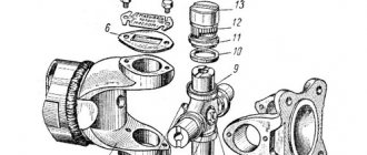
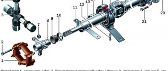
Rear wheel hub of a GAZ-53A1 car – brake drum fastening screw, 2 and 16 – outer and inner hub bearing, 3 – bolt – axle shaft remover, 4 – installation pin, 5 and 6 – nut and locknut for bearing fastening, 7 – lock washer, 8 – axle shaft mounting stud, 9 – cap nut securing the inner wheel disk, 10 – nut securing the outer wheel disk, 11 – wheel hub, 12 – brake wheel cylinder, 13 – rear axle beam, 14 – axle shaft, 15 – oil seal. – hang out wheel; – unscrew and remove the stud nut and remove the axle shaft 14; – unscrew the lock nut 6, remove the lock washer 7, unscrew the nut 5 and remove the hub 11 from the rear axle beam journal; – remove the hub bearings, wash in kerosene, check and, if necessary, replace, lubricate with grease 1 d-13 and install in place; – fill the inner cavity of the hub with grease 1-13; – install the hub in place; – with one hand, tighten nut 5 with a wrench with a 350-400 mm long crank, while rotating the wheel so that the rollers are in the correct position position.
Under the axle shaft, this is, say, SIO, NT fossil is not required, if you are going to use the DOS version of the soaper, dig up some BNU or X00.
The eccentricity is equal to the square root of the difference in the squares of the major and minor semi-axes of the orbit, divided by the semi-major axis.
According to modern radar measurements, the semimajor axis of the earth's orbit is 149,597,870 + 1.6 km.
occurs along ellipses, the major semi-axis of which is perpendicular to the surface of the solid body, and the minor axis is parallel to the direction of wave propagation.
planets assume a planetocentric sphere with radius , where a is the semimajor axis of the planet’s orbit. The values of r, expressed in astronomical units, are given in the table. Spheres of action of gravity and planets Planets p, a.
in the USSR by F.N. Krasovsky (1873–1948) and A.A. Izotov (1907–1988): according to their definitions, the minor axis of the Earth’s spheroid, coinciding with the Earth’s rotation axis, b = 6356.86 km, and the semimajor axis, perpendicular minor axis and lying in the plane of the earth's equator, a = 6378.24 km.
The latter are most easily determined if the stars form a binary system for which the orbital semimajor axis a and the orbital period P are known.
Drive shaft (axle shaft): design, functions, features
Almost every car enthusiast knows what an axle shaft is in a car. In most cases, the driver has enough information that this is “that thing that goes from the differential to the wheel” to safely drive to work and home. But there are cases when the drive shaft requires intervention, and then it is better to find out as much as possible about it even before visiting the service station.
Replacing the axle shaft
If you are a careful driver and rarely go off-road, then your axle shaft can serve you without breakdowns or replacements. But if, for any reason, the axle shaft ceases to perform its functions, most car enthusiasts have many questions and problems with replacement. Now we will try to sort it out to reduce troubles and answer all questions.
Replacement of the drive shaft occurs together with the hinges , if the central shaft becomes unusable, or in cases where its design consists of joints (CV joints).
If during processing of the transmission you hear uncharacteristic sounds, namely crunching of the hinges, as well as increased vibration, then this is a direct indicator of a breakdown of the drive shaft. A more serious and obvious breakdown may occur, the shaft itself breaks directly, you will immediately notice this.
To avoid unexpected breakdowns, try to diagnose the drive shafts yourself. Conduct a visual inspection of their condition at certain intervals. If you see strange streaks of lubricant, then do not delay, change the protective covers and contact a service station for a more detailed diagnosis. There, a specialist will pay attention to corrosion and possible backlashes. And if suddenly the breakdown turns out to be serious, then in such cases it is necessary to change the part. Otherwise, the chance of losing a wheel far from a service station increases.
There is no replacement period for the axle shaft. If any malfunction occurs, replace it. In addition, it is not at all necessary to change both axle shafts at once. The only thing that changes is the way in which the breakdown occurred.
Design, operating principle of PV
The design of the axle shaft is designed in such a way that maximum torque transmission is ensured regardless of the current position of the wheels. Let's look at what the axle shaft consists of:
Physically, the axle shaft is a section of a solid pipe, to the ends of which adapters for mounting angular velocity joints are attached by welding. To prevent these parts from turning, they are splined.
The shaft is additionally fixed at the junction with the adapter with a locking ring, which prevents the possibility of the axle detaching from the CV joint.
This is the double-joint design used on most front-wheel drive vehicles, with both joints performing slightly different tasks. The internal ones dampen vibrations during vertical movements of the wheels (hitting over uneven road surfaces), the external hinges are responsible for the movement of the wheel rims when the direction of movement of the vehicle changes, that is, when turning.
The wheel hub is attached to the PV using a flange - this method is considered the most reliable and therefore has become widespread. From the inside, fastening to the semi-axial gear is carried out using splines. There are also flangeless PVs, which also have splines on the outer side of the shaft onto which the hub or wheel flange is attached (this design is used, in particular, in KrAZ/MAZ trucks).
Causes of axle shaft malfunction
When a vehicle moves, many loads occur on the suspension elements. Some of them are also perceived by the drive shaft:
- bending moment formed under the influence of gravity;
- tangential bending moment, which appears during sudden acceleration/braking;
- lateral impact resulting from vehicle skidding;
- loads that a vehicle experiences when exposed to strong gusts of side wind.
When driving on roads of frankly poor quality, the drive shaft is exposed to extreme loads. Although the shaft itself is made of very strong steel and its breakdown is extremely rare, this cannot be said about the other axle shaft components. It should be borne in mind that in most cases, a breakdown of the transmission leads to a complete or, at best, partial loss of controllability of the vehicle, so the care of this transmission part should be given paramount importance.
First of all, we are talking about regularly checking the condition of the bearings - they are considered the “weak link” in the design of all types of axle shafts.
In addition to premature wear of drive shaft parts, mechanical damage may also occur as a result of exposure to foreign objects.
We list the main symptoms of drive shaft malfunctions:
- wheel slip that occurs when changing gears;
- deterioration or inability to engage some gears;
- the appearance of sediment in the system in the form of foam;
- presence of transmission oil leaks;
- the appearance of unusual noises localized in the vehicle drive area;
- the car moving away from a straight path, as well as wobbling to the sides;
- the appearance of vibration coming from the bottom of the car.
Of course, almost all of these signs are indirect, since they may indicate other malfunctions not related to the drive shaft.
Most often, as already mentioned, the normal functioning of the axle shafts is disrupted due to bearing wear. This malfunction, in turn, causes TM leakage and loss of sealing of the axle shaft seals.
Although transmission oil does not operate under as extreme conditions as motor oil, it is also subject to high heat. Liquifying when heated, it partially loses its lubricating characteristics, the friction force in the shaft units increases, which leads to a violation of the integrity of the seals.
The principle of operation of axle shafts on a car
Although the drive shaft, often referred to as the axle shaft, is not part of the driveline, it is part of the vehicle's transmission and is an important part of it.
Today we will look at what tasks the PV performs, what axle shafts are, and how they function.
Let's also consider why these transmission components fail and how to increase their service life.
Vehicle axle structure
The overall design includes 3 main elements:
In fact, the axle shaft is a shaft of one length or another (depending on the characteristics of the vehicle). Adapters for installing CV joints are attached (welded) to the shaft.
In order to prevent twisting, the connections are splined. At the end of the adapter, the shaft is secured with a retaining ring, which prevents the shaft from accidentally coming out of the CV joint.
The inner CV joint is responsible for moving the wheel during vertical movement of the suspension, while the outer one is responsible for turning the wheel.
If we talk about the types of axle shafts of a car, axle shafts according to types and types are divided into:
The unloaded axle shaft is installed on trucks, buses, etc. In this case, the axle shaft stands inside the bridge, and the wheel hub rests on the bridge beam with two bearings.
This design means that the bending moment is borne by the bearings, and the only task of the axle shaft is to transmit torque. It turns out that such an axle shaft does not experience additional loads compared to a half-loaded one.
Balanced and semi-balanced axle shafts
general description
Bridges based on the design of the axle shafts are divided into two categories: 1. Bridges with semi-balanced axle shafts; 2. Bridges with balanced axle shafts.
Semi-balanced axle shafts
In a scheme with a semi-balanced axle shaft, the axle shaft transmits torque and absorbs lateral loads and the weight of the vehicle.
Usually used on passenger cars where the axle load is low. Pros:
simpler design;
less weight Cons:
less load capacity; if the axle shaft breaks, the wheel simply separates from the car, with all the ensuing consequences
In a scheme with a balanced axle shaft, the axle shaft transmits only torque and does not perceive lateral loads and the weight of the vehicle. Usually used on trucks where the axle load is high. Pros:
high load capacity; if the axle shaft breaks, you can simply remove it (if it is an all-wheel drive vehicle, you can continue driving on one axle)
Minuses:
more complex design; more weight
Source
Classification of axle shafts
Since the drive shaft consists of many elements, they are all made from different materials. The axle shaft itself is made from special grades of steel with additives that ensure the highest strength of the product for all possible loads.
Depending on the manufacturing method, the following types of axle shafts are distinguished:
- solid, when the drive shaft does not have removable elements. Most often, this design is used on the front axle of a vehicle. It is clear that the one-piece design is the most durable, but it cannot be called a universal solution;
- monoblock axle shafts are also solid, but they are hollow inside - this reduces strength, but significantly facilitates the design;
- Ball bushing axle shafts are usually installed on off-road vehicles. The bushing is precisely the element that ensures maximum smooth running and helps reduce noise during operation of the axle shaft.
Let's consider what forces act on the drive shaft when the car moves. This, of course, is the force of gravity, which is activated during the vertical component, as well as lateral and tangential loads that occur when the car turns, during skids, when driving along a section of the road with a transverse slope, as a result of the influence of lateral air flow (gusts of wind) .
Depending on the design of the external fastening, which determines the level of loading of the shaft by bending moments of different directions, the following types of axle shafts are distinguished:
- completely unloaded;
- semi-unloaded;
- unloaded by ¾.
In the latter case, the shaft design provides for only a support bearing to which the wheel disk/hub is attached. Since this design is not able to absorb bending loads, it is used relatively rarely.
A semi-loaded drive shaft is usually installed on passenger cars, as well as light-duty trucks that do not experience significant vertical loads.
In this case, the installation location of the bearing is between the primary housing and the axle shaft itself, which, in turn, is attached to the wheel hub. This design leads to the appearance of multidirectional bending moments acting on the PV in the horizontal/vertical planes, as well as in the plane of rotation of the wheel on the shoulder, the length of which is equal to the diameter of the tire.
- relatively simple design;
- low mass.
- low ability to withstand loads;
- Failure of the PV leads to the loss of a wheel, which, when driving at speed, causes loss of controllability and overturning of the vehicle.
A fully balanced drive shaft is the prerogative of buses and heavy trucks. Inside the bridge, such a structure is installed freely; fixation on the bridge beam is carried out by means of two bearings, which are responsible for damping all types of bending moments. The axle shaft turns out to be free and is responsible only for transmitting torque from the power unit to the wheels.
- ability to withstand significant loads;
- the breakdown of the axle shaft is not critical, replacing it is not difficult (when driving an all-wheel drive vehicle, you can even move further using another axle).
The disadvantages are the exact opposite of the advantages of semi-balanced axle shafts:
- solid weight of the drive shaft;
- complex design.
Half shaft
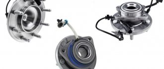
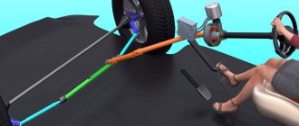
A car's axle shaft (drive shaft, drive) is a special shaft through which torque is transmitted from the internal combustion engine to the drive wheels. The axle shaft (drive axle shaft) allows you to create moving contact and effectively transmit force, while maintaining the ability to turn the wheels. The axle shaft also reduces vibrations and takes on various loads (gravity, traction, braking force, bending moments, etc.).
Structurally, two joints (CV joints) are attached to the axle shaft, which allow uniform transmission of torque regardless of the position of the wheels and suspension parts. As a result, vibrations on the steering wheel are reduced, the car moves smoothly, and power losses from the engine to the wheels are minimized.
Recommendations for replacing internal CV joints
The automatic transmission system also contains a number of bearings, which can cause the entire gearbox to fail. For example, such vital elements for a car include the outboard intermediate bearing of the drive shaft. Of course, if one bearing breaks, it won’t lead to anything serious, but still, driving with a strong roar from under the hood is not very pleasant.
Another detail that is worth paying attention to is the hinge kit; the drive shaft cannot do without this structural element. It is this that ensures the uniform transmission of traction forces that fall on the drive wheels.
Most often, drive shaft joints fail due to a leaky boot. The malfunction of this part is immediately visible; you will feel how unevenly the weight of the car is distributed on the wheels while driving. Of course, first of all you need to check the tire pressure, and then deal with the automatic transmission.
The constant velocity joint is a bowl-shaped housing with an axle shaft (trunnion), into which a cage and a cage with bearings are inserted. Special grooves are applied on the outer surface of the holder and the inner side of the body. When in motion, the inner race transmits force to the CV joint housing, causing it to rotate.
The dimensions of the parts are different: the internal CV joints are made more massive compared to the external ones.