The successor to the famous “commander” UAZ 469 is the UAZ 31514, which has appeared on the domestic market since 1993. According to industry classification, the car received a new index, as well as a contactless ignition system, while remaining as reliable and trouble-free in operation as its predecessor.
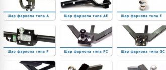
Factory electrical wiring diagram for UAZ 31514
Historical reference
Traditionally, the UAZ 469 was produced in two versions:
- Cargo-passenger version - 7 seats and 100 kg of luggage;
- Commander version - 2 seats for passengers and 600 kg of luggage.
For reference: regardless of the version, the UAZ 469 can tow a trailer with a total weight of 850 kg.
Industry standard 1945
According to the old vehicle classification system, in force since 1945, the UAZ 469 was produced under this name, using an alphanumeric name:
- The letter abbreviation UAZ stood for Ulyanovsk Automobile Plant;
- 469 is a serial factory index assigned by the enterprise itself to its models and developments.
For reference: according to the industry standard of 1945, each automobile plant was assigned a specific numbering. For MZMA, which produced Moskvich 408 and 412, these are numbers from 400 to 449, for the Ulyanovsk Automobile Plant these are numbers from 450 to 484, etc.
1966 Industry Standard
Although at the time of the release of the UAZ 469 (1972) a new industry classification system was adopted (industry standard OH 025270-66), the car plant continued to use the name according to the old standard.
However, in 1985, the automaker was forced to change its name in accordance with current requirements:
- the car was assigned a four-digit number - 3151;
- According to the new system, the car can be called in the documentation as UAZ 3151.
For reference: industry standard OH 025270-66 prescribes determining the type of vehicle by engine displacement, length and weight. The first digit indicates the class of the car, the second – the type (truck or passenger car), the third and fourth – the factory model index.
The car plant named all further modifications and new models in accordance with current standards. In particular, the UAZ Patriot, which appeared in 2005, according to the industry classification, received the “correct” designation - UAZ-3163. For greater identification, the factory instructions contained both names.
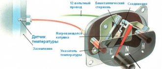
Engine compartment
For many years, the main power unit of the UAZ 469 was the in-line 4-cylinder UMZ-451MI carburetor type. The engine capacity was 2445 cc. cm, power – 75 hp.
With this engine produced by the Ufa Motor Plant, the UAZ 469 lasted on the factory assembly line until 1985.
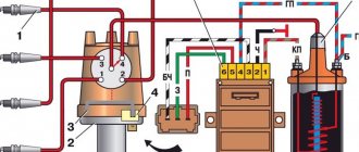
It was distinguished by a simple single-wire 12-volt ignition circuit, which consisted of (according to the numbering):
- rechargeable battery (AB);
- mechanical ground switch;
- electronic battery charge voltage regulator;
- alternator;
- ammeter on the instrument panel;
- ignition switch (switch);
- ignition breaker contact group;
- directly to the ignition distributor (distributor);
- capacitor built into the distributor;
- ebonite distributor cover with leads for high-voltage wires;
- ignition distributor slider;
- spark plugs;
- high voltage wires from the ignition coil;
- additional coil resistance;
- starter relay;
- directly to the high-voltage ignition coil;
- electric starter.
For reference: on the black and white diagram of the ignition system shown, the letters indicate the wiring on the UAZ 469 according to the color of the wires. K - red, O - orange, G - blue; F – purple and Ch – black (according to the capital letters of the names).
New modifications of the legendary SUV received more modern engines and a modified electrical circuit.
In particular, the UAZ Patriot wiring diagram includes:
- electronic fuel injection system;
- contactless ignition system;
- climate control system inside the car;
- alarm system, etc.
Power supply
For normal operation of the power unit, the UAZ 31514 wiring diagram includes:
- Distributor;
- Transistor switch;
- High voltage wires;
- Idle speed microswitch;
- Forced idle solenoid valve;
- Spark plug;
- Electric starter;
- Ignition coil.
The power unit is started by an electric starter. The starter is controlled remotely from the cab. The positive wire from the battery is attached to the starter terminal. The starter is equipped with a retractor relay. It is necessary to turn on the electric motor and engage the drive gear with the engine flywheel.
conclusions
The UAZ 469 has proven itself to be a fairly reliable off-road vehicle for multi-purpose use. The civilian population actively uses it for their own purposes also due to the fact that it can be serviced with its own hands, using factory documentation and advice from craftsmen.
How is the electrical circuit of the UAZ 31514 different? The car received a completely different ignition system from the previous one; it became contactless. At the same time, reliability remained at the highest level, just like that of the UAZ 2206. The choice of this particular achievement of the modern automotive industry is associated not only with the electrical wiring, but also with the quality of the overall assembly. All models, including UAZ 390945 and others, amaze with their reliability, durability, strength, and ease of use.
1 — front lamp; 2 - headlight; 3 — sound signal; 4 - fuse; 5 — side direction indicator; 6 — additional resistance; 7 — heater switch; 8 — heater fan electric motor; 9 — engine compartment lighting; 10 - generator; 11 — turn signal and hazard warning relay; 12 — spark plugs; 13 — heater resistance (resistor); 14 — starter relay; 15 — ignition coil; 16 — sensor-distributor; 17 - switch; 18 — battery; 19 — ground switch; 20 — electric washer; 21 — emergency vibrator; 22 — fuse block; 23 — oil pressure indicator sensor; 24 — coolant temperature sensor; 25 — coolant overheat sensor; 26 — emergency oil pressure sensor; 27 — sensor of insufficient brake fluid level; 28 — starter; 29 — headlight relay; 30 — portable lamp socket; 31 — parking brake warning switch; 32 — brake signal switch; 33 — speedometer; 34 — indicator of insufficient brake fluid level; 35 — parking brake activation indicator; 36 — turn signal indicator; 37 — indicator for turning on the main beam of headlights; 38 — carburetor microswitch; 39 — windshield wiper; 40 — block of the EPHH system; 41 — windshield wiper relay; 42 — electromagnetic valve of the EPHH system; 43 — warning lamp for emergency oil pressure; 44 - warning lamp for coolant overheating; 45 - central light switch; 46 — alarm switch; 47 — fuel level indicator; 48 — coolant temperature indicator; 49 — oil pressure indicator; 50 - voltmeter; 51 — interior lamp; 52 — interior lamp switch; 53 — right steering column switch; 54 — horn switch; 55 — fuel level sensor; 56 — left steering column switch; 57 — fuel level sensor switch; 58 — cigarette lighter*; 59 — rear fog lamp switch; 60 - thermal (bimetallic) fuse; 61 — ignition switch; 62 — ignition relay; 63 — reverse light switch; 64 — rear light; 65 — additional brake light*; 66 — reversing light; 67 — rear fog lamp; 68 — license plate light; 69 — trailer socket*. * Installed on car parts.
The presented model is more reliable, for example, 390994, the injector of which causes many problems for customers and requires close attention to temperature sensors. The electrical equipment of the UAZ 469 or UAZ 3303 had a simpler system, there were no such problems, and the later electrical circuit of the UAZ 2206 was made much simpler, which did not in any way affect reliability and quality.
Light signaling
For safe movement on public roads, the car is equipped with a light alarm. This includes direction indicators, brake lights, reversing lights and hazard warning lights.
The brake light switch is driven by the brake pedal. The direction indicators are controlled by a 3-mode switch located on the steering column. A separate switch is provided to control the alarm.
WARNING: The hazard warning light circuit is protected by a fuse. It is installed on the partition of the engine compartment. When a short circuit occurs, the fuse inhibits the power supply and the alarm relay.
Features of the model and its equipment
The wiring diagram still amazes with its quality. The legal successor of this vehicle was another model 31514, which began production in 1993 and immediately won a circle of its admirers. The new models are significantly different from the previous ones. Not only has the design been improved, but so has the wiring. For example, the electrical circuit of the UAZ 390994, the injector of which could cause inconvenience, did not have a special temperature sensor. New models have contactless ignition. The node includes:
- low voltage ignition coil;
- electronic transistor switch;
- distributor, i.e. sensor-distributor;
- electrical additional resistance;
- special emergency breaker;
- fuses (unit installed).
For example, type 390994, whose injector caused problems at high speeds, did not have such high-quality and sophisticated wiring. And the disadvantage of such a network element does not ensure the closure of the damper for the intake manifold. Servicing such a system is inconvenient; the absence of just one sensor is what makes 390994, whose injector is so “problematic,” not so in demand. The situation was resolved by using a better system and additional cables.
Electrical wiring components for UAZ 469, UAZ 390945 and other models
The electrical circuit of the UAZ 3151 4 includes 69 positions; it is possible to additionally connect special fog lights, but the installation of a switch type 343.01.03 is required. It will be mounted directly on the dashboard in a convenient location. The general wiring diagram of a machine includes an extensive list of different devices.
This is a front light, headlights that are easy to replace if necessary. An audio signal is also connected to the general system. Further, the UAZ wiring diagram includes a special fuse and additional resistance. The circuit has a connection to the side direction indicators, and a switch for the heater is located right there.
The wiring supplies the generator, there are connection points for the light that illuminates the engine compartment, and outputs for the heater fan motor. Modern UAZ electrical wiring includes spark plugs powered by it. A relay is installed for indicators; it is used to ensure the operation of emergency and turn signals.
The electrical circuit has outputs to a coil, a starter relay, there is a special sensor-distributor, and a switch. In one area there are the following points: turn off the masses, hazard warning lights, battery, electric washer. There is a separate connection for the fuse box and the following sensors:
- emergency pressure for oil;
- fuel readings;
- for oil pressure indicator;
- overheating of used coolers;
- temperatures of the coolers used;
- determining the brake fluid level.
1.Low voltage ignition coil; 2.Transistor electronic switch; 3. Sensor-distributor (distributor); 4.Electric spark plugs; 5.Fuse block; 6.Emergency breaker; 7.Additional electrical resistance.
The electrical diagram includes connection points for the starter, speedometer, windshield wiper and relay for it, EPH unit, voltmeter. There are the following components:
- relay for car headlights;
- sockets used to power portable lamps;
- parking brake switches, braking systems.
For electrical equipment of UAZ 31512(14) or UAZ 390945, the following switches are installed:
- for brake signal;
- for parking brake;
- alarm;
- interior light lamps;
- sound signal;
- rear fog lamp;
- ignition;
- reverse lights.
The electrical circuit of the UAZ-469 combines all the devices and instruments used in the car. If malfunctions occur in the system, full operation of the car can cause difficulties for the car owner, so all breakdowns must be promptly repaired. You can learn more about malfunctions, as well as wiring prevention, from this material.
UAZ ignition system – Ignition – Vehicle
Currently, non-contact combustion systems are used. Of course, they are made on an electronic basis. The contacts are no longer able to ensure reliable engine operation at 6000 rpm. At this speed, the contacts no longer have time to close. The spark power drops. Such problems do not occur in contactless ignition systems. In previous issues, the sensor-distributor assembly was described, in old books called a distributor. The spark discharge energy is one and a half to two times higher than in battery ignition systems. Thanks to this, the car starts easier, has less toxicity and fuel consumption. The engine can develop a high rotation speed. That’s all the difference, and a fundamentally new unit – the commutator. It’s worth talking about it, since the quality of work depends on the brand of the switch. As an example, let's consider the electronic ignition systems of cars of two brands - GAZ and UAZ.
The switch is an amplifier of the electrical signal from the sensor and at the same time it provides power to the ignition coil. As soon as a current pulse arrives from the sensor, the commutator stops supplying current to the primary winding of the coil. In this case, a high-voltage current pulse appears in the secondary winding. At the same time, a spark jumps at the spark plug, igniting the mixture of gasoline and air.
The ignition system of UAZ vehicles consists of a distributor sensor (distributor) 33.3706 or 19.3706, an ignition coil B-116, an additional resistor 14.3729 (variator), a switch 13.3734, spark plugs A11, and an emergency vibrator 5102.3747, which I will discuss in more detail below. Figure 1 shows a functional diagram of the UAZ ignition system. The most interesting switch for UAZ cars is that it has several completely unique characteristics. I would prefer it to Volgovsky, especially since such a replacement is possible. The UAZ switch has the following distinctive properties:
When the crankshaft rotates at less than 500 rpm, the signal at the sensor output does not change very quickly. This mode occurs when the engine is started by the starter. The switch circuit is designed in such a way that in this mode, instead of one spark, many sparks flash across the spark plug. Multi-spark ignition on UAZ makes it easier to start the engine in cold weather. Here is part of the answer to why the Volga starts worse than UAZs in the cold (later we will talk about the differences between the starters of these models and much more, which gives advantages to the UAZ UMZ-4178 engine over the ZMZ-402).
If the voltage in the on-board network is more than 16 volts (for example, the relay-regulator has burned out), the UAZ switch will perform an emergency shutdown of the ignition. This measure allows you to save an expensive battery from destruction. I know of a case where a Volga car owner’s expensive radio burned out. If he had had a UAZ switch, nothing would have happened.
The designers of the Ulyanovsk Automobile Plant equipped the UAZ 31512 with electrical equipment. The UAZ 31512 electrical circuit diagram may be needed if necessary to repair the car. For ease of repair, the manufacturer installed wires with insulation of different colors on the car.
What is included in the electrical circuit?
The above is a form of electrical wiring diagram.
Regardless of which UAZ you use - old or new model - the main components of the electrical network are as follows:
- Dashboard. It displays the main sensors and indicators indicating that a particular device is turned on. Tidying allows the driver to know at what speed he is moving, how much fuel is left in the tank, what the crankshaft speed is and what the engine temperature is. In addition, there are many lights installed on the tidy that light up synchronously with the switching on of certain devices.
- Accumulator battery. The battery is an integral element of any car; it allows you to power the vehicle’s equipment when the engine is turned off, and also helps the ignition system in starting the power unit. If the battery is discharged, you will not be able to start the engine in the traditional way - you will either need to recharge it or try to start it with a pusher.
- A generating device, the failure of which will also make it impossible to start the engine. This unit provides voltage to all devices and devices used in the car while driving.
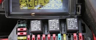
- Fuse block. This device contains all the safety devices designed to protect electrical circuits and devices from overvoltage. If there is a power surge in the network, then the main blow will be taken by the fuse (author - Ben & Ice Video Master channel).
Salon block
Structurally it is also basic. In old and new cars, the panel is installed under the dashboard on the left side of the steering wheel. The main fuse links responsible for most of the motor equipment and instruments are concentrated here.
Until 2007
The first modifications of older years of production were not very different in design from carburetor cars of the modern type. A standard system of fuses and relays is used here, which is relevant for most cars on CIS roads.
The description of the new generation after 2015 differs significantly, but due to the minimum number of cars on the market, they are not listed.
Until 2011
There were no major changes in the design. Similar engines and equipment were used here. When updating the electrical circuit, the factory did not provide for the installation of an updated mounting panel. All fusible links remained in their places, and the new elements were taken out separately.
After 2011
The latest modification, produced in 2016-2018, was distinguished by the presence of an injection engine. Here an additional installer has appeared, who is responsible only for atomizing fuel and is installed under the hood.
As a result of the modification, the car became more economical and slightly more powerful.
Common faults
As for breakdowns in the electrical wiring of the Ulyanovsk Automobile Plant product, they are as follows:
- Battery low. As we have already reported, without a battery, normal operation of the motor will be impossible, and the same applies to electrical equipment. Battery discharge can occur for various reasons. Due to evaporation of the electrolyte or its leakage as a result of damage to the battery case, damage to the plates inside the structure, or their short circuit. Typically, such problems are caused by wear and tear of the device or its improper operation.
- Failure of the safety device. Its burnout can occur as a result of wear or a power surge. Before installing a new fuse, you need to test the circuit to make sure there are no surges. If they do occur, then the cause must be determined and eliminated, otherwise the problem will recur.
- Broken wire. This problem is relevant not only for UAZ, but also for other cars. To prevent breaks, wires should be laid away from moving parts of the body.
- There is no contact with the device. This usually occurs as a result of a broken wire, but if it is intact, then the problem lies in the contact. The end of the wire could simply come off or oxidize. Oxidation is one of the main problems in domestic cars.
- Generator failure. The design of the generator unit itself is quite complex, so there can be many problems in its operation. If the generator itself works, but incorrectly, first of all it is necessary to diagnose its belt - it may be overtightened or tensioned too loosely, in which case adjusting it will solve the problem.
Windshield cleaning and horn
The windshield of a UAZ 31 514 car is equipped with two brushes. They are driven by an electric motor. The engine has two rotor speeds. The windshield cleaning system includes an electric washer motor. The washer and wiper motors are controlled by a combination switch.
For safe driving, the machine is equipped with a sound signal. The horn button is installed on the steering wheel.
REFERENCE: To prevent fire in the event of a short circuit, the horn circuit is protected by a fuse.
From the above it follows that the electrical equipment of the UAZ 31 514 is necessary for the normal operation of the vehicle. The electrical circuit diagram allows you to perform repairs and maintenance yourself. For convenience, the manufacturer wired it with multi-colored wires.
Source
Prevention measures
What preventative measures will help protect your car’s electrical network from malfunctions:
- When the engine is off, limit the use of electrical equipment, as the battery will drain faster;
- From time to time, diagnose the performance of the battery and check its charge;
- ensure reliable insulation of the wiring;
- never use homemade fuses.
The electrical equipment of UAZ-31512, UAZ-31514 and UAZ-31519 vehicles is made according to a single-wire circuit. The negative terminals of the sources and consumers of electricity are connected to the body and other components of the car, which act as a second wire. On-board DC network, with a nominal voltage of 12 Volts. Protection of electrical circuits is organized through a fuse box.
To switch the main circuits of the car, a combined ignition switch is used, consisting of a contact part and a mechanical anti-theft device with a lock. When the engine is not running, all consumers are powered by the battery, and after the engine is started - by alternating current with a built-in rectifier unit. When the generator is running, the battery is charged.
When the engine is idling, the generator rotor speed and, accordingly, the supplied current are insufficient to provide power to powerful consumers, such as headlights, windshield wipers, electric fans, and alarms. In this mode, the battery will be discharged.
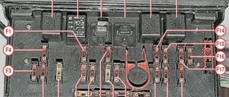
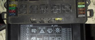
Location and purpose of fuses for electrical circuits of the on-board network of UAZ-31512, UAZ-31514 and UAZ-31519.
To protect the vehicle's external lighting electrical circuits from overload, a bimetallic fuse 29.3722 or similar is used, which is installed under the instrument panel on the left. Three 10 Amp fuses are installed in the PR103 fuse box, mounted on the partition of the engine compartment. They protect:
No. 1 - circuits of control devices; No. 2 - direction indicator circuits; No. 3 - alarm and sound signal circuits.
Fuse No. 1 is located closer to the right side of the vehicle. The heater fan motor power circuit is protected by a fuse with a rated current of 6 Amps. The fuse is located on the wiring harness next to the heater switch. UAZ-31512, UAZ-31514 and UAZ-31519 vehicles can be equipped with other additional fuses, depending on the configuration.
Checking the electrical circuits of the on-board network of UAZ-31512, UAZ-31514 and UAZ-31519 under voltage.
Live circuits are also checked with an ammeter. The voltmeter is connected in parallel to the device or circuit section being tested. Measurement range 0–15 or 0–25 Volts DC. The negative wire (probe) is connected to ground, the positive wire is connected to consumers or current sources. By the voltage drop, you can determine a malfunction of the supply circuit - a break, oxidation of contacts, etc., as well as a short circuit in the consumer.
To check live circuits, you can also use a test lamp with a power of no more than 3–4 W, designed for a voltage of 12 Volts, for example the AMH12-3 lamp used in the instrument panel.
The ammeter must have an upper measurement limit of at least 10 Amps DC, as well as overload protection. We connect the ammeter in series with the device being tested. The plus of the device is connected to the current source, and the minus is connected to the consumer’s plus. If the current is less than required, then the electrical circuit is faulty, and if it is more, a short circuit has occurred in the consumer.
Consumer power
The power unit is powered by a battery and a DC generator. When the internal combustion engine is not running, power is provided by a 12-volt battery.
After the engine starts, the consumers are supplied by a DC generator. The generator is equipped with a relay regulator that prevents voltage drops at different engine speeds. The DC generator and the battery are connected in parallel in the circuit.