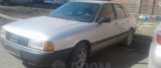
A little history of Daewoo Matiz
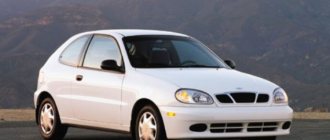
This car model has been produced since 1998. To date, 2014, the third generation of Daewoo Matiz (M300) has already been released. Matiz of the first generation (M100? M150) and second (M200? M250) Hatchback has 5 seats. All models are equipped with a manual gearbox, and the consumer has a choice of engines: 0.8 liters or 1. After a slight restyling of the car in 2012 (the M200 model was released), in China it was called Chevrolet Lechi. Also there, the car once again underwent minor modifications and became known as “Baojun Lechi” with engines of 1.0 liters (69 hp) and 1.2 liters (86 hp).
Video about the crash test of Daewoo Matiz 1,2 and 3rd generation, respectively - 2000, 2005 and 2009:
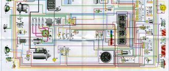
Electrical diagrams of Daewoo Matiz:
1. Numbering of contacts in electrical connectors:
2. Diagram for starting the Daewoo Matiz 1.0 l engine and charging the battery:
3. Electrical diagram for starting the engine and generator connections (0.8 l engine):
4. Engine management system 1.0L:
8. Electrical circuits of the Daewoo Matiz 0.8 l engine management system:
11. Electrical diagram of Daewoo Matiz: reversing lamps, brake lights, side lights and license plate lights:
12. Connections of the relay and fuse box located under the hood of the car (1.0 l engine):
16. Connections of the relay and fuse box located in the car interior (1.0 l engine):
18. Connection diagram of relays and fuses (0.8 l engine):
19. Wiring diagram of the Daewoo Matiz 1.0 liter instrument cluster:
22. Connections of the instrument cluster of a car with a 0.8 liter engine:
24. Turning on the panel backlight and instrument cluster (0.8 l):
25. Turning on the headlights and the headlight beam direction control (1.0):
26. Electrical diagram for turning on the headlights of Daewoo Matiz 0.8 l:
27. Turning on the car headlight beam direction control (0.8):
28. Scheme for switching on fog lights and fog lamps in the rear light (1.0):
29. Wiring diagram for Daewoo Matiz 0.8 liter for turning on fog lights and fog lights in the rear light:
30. Direction and hazard indicators, electrical diagram:
31. Diagram of the operation of the interior and trunk lighting bulbs, as well as the activation of the front door electric windows:
32. Electrical diagram of windshield and rear window wipers and washers of Daewoo Matiz:
33. Heated car tailgate glass and diagram of the cigarette lighter and clock:
34. Sound reproduction system:
35. Daewoo Matiz 1.0 car air conditioner and fan:
36. Electrical circuit for switching on the air conditioner and fan Daewoo Matiz 0.8 liter:
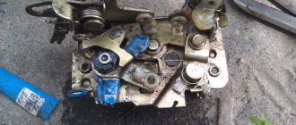
Block under the hood
It is located on the left side under the protective cover.
On the reverse side of which the current block diagram will be printed.
Scheme
Description of fuses
1 (50 A) - ABS.
2 (40 A) - constant power supply to devices when the ignition is turned off.
3 (10 A) - fuel pump . If the fuel pump does not work when you turn on the ignition (you cannot hear the sound of its operation), check relay E, this fuse and the voltage on it. If there is voltage at the fuse, get to the fuel pump and check if voltage is supplied to it when the ignition is turned on. If it does, you most likely need to replace the fuel pump with a new one. When installing a new one, also change the pump module filter. If there is no voltage to the pump, most likely the problem is in the wiring or the fuel pump circuit breaker (for example, in an installed alarm system). The wires could be frayed under the seats, in the harnesses, or there might be poor contact at the joints/twists.
4 (10 A) - ECU power supply, fuel pump relay winding, ABS unit, generator winding at start, terminal B from ignition coils, speed sensor.
5 (10 A) - reserve.
6 (20 A) - stove fan . If the stove stops working, check this fuse, its fan motor by applying 12 V voltage to it, as well as the handle and cable of its drive going to the heater tap. If the heater blows cold, this cable could fly off; it is located on the driver's side near the center console under the dashboard. If the heater speeds are not adjustable, also check relay C under the hood. It could also be an air lock.
To remove air from the system, drive up a hill with your front end up, open the expansion tank cap and release the gas. On a hot engine, be careful when opening the reservoir cap. It could also be a problem with the heater core or clogged air intake pipes.
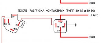
7 (15 A) - heated rear window.
If the heating stops working, check the fuse, as well as the contacts in its socket. If there is poor contact, you can bend the terminals. In many models, due to the lack of a relay in the rear window heating circuit, the power button receives a large current load, so it often fails. Check its contacts and if it no longer locks in the pressed position, replace it with a new button. You can get to it by removing the dashboard trim or pulling out the radio. It is best to install a relay, thereby relieving the load on the button. In some models, a relay C under the hood is installed on this button, check it.
Also check the threads of the heating elements for breaks; broken threads can be sealed with a special glue containing metals. It could also be the terminals at the edges of the glass, a poor grounding connection, or the wiring from the rear window to the button.
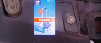
8 (10 A) - right headlight, high beam . 9 (10 A) - left headlight, high beam . If your high beams stop lighting when you turn on this mode, check these fuses, fuse F18, the contacts in their sockets, the lamps in the headlights themselves (one or two could have burned out at once), relay H in the engine compartment and its contacts, the steering column switch and its contacts. Often the contact in the switch connector is lost, disconnect it and check the condition of the contacts, clean and bend if necessary. Also check the wires coming from the headlights for breaks, short circuits and insulation damage. The negative on relay contact H may also disappear due to oxidation or burnout of the track in the mounting block.
To replace the lamp in the headlight, disconnect its connector with wires, remove the rubber cover (boot) from the side of the engine compartment, squeeze the “antennae” of the lamp clamp and remove it. When installing a new lamp, do not touch its glass part with your hands, as Hand marks will darken when turned on. The lamps in the headlights are double-filament, one lamp for low and high beams; for the dimensions, separate smaller lamps are installed in the headlights.
F10 (10 A) - right headlight, low beam . F11 (10 A) - left headlight, low beam . Same as high beam, except F18.
12 (10 A) - right side, clearance lamps.
13 (10 A) - left side, clearance lamps, license plate lighting lamps . If your side light goes out, check these fuses and relays I and their contacts. Check the serviceability of the headlight lamps, connector contacts and wiring.
14 (10 A) — air conditioning compressor clutch (if equipped) . If your air conditioner does not work and the clutch does not move when you turn it on, check this fuse and relay J, as well as the power button and its contacts, and wiring. The movement of the operating clutch should be audible through a characteristic sound when the air conditioner is turned on. If the clutch works but cold air does not flow, the system most likely needs to be charged with freon.
Do not forget that in winter it is necessary to periodically turn on the air conditioner in a warm place - a box or a car wash, so that the seals are lubricated and remain in good condition after winter.
15 (30 A) - electric radiator cooling fan . If your radiator fan stops turning on, check relays A, B, G, this fuse and their contacts. The fan is connected through a thermal switch, which is installed on the radiator; 2 wires are connected to it. Take them out and short them together; when the ignition is on, the fan should start working. If it operates in this position, most likely the thermal switch is faulty; replace it.
If the fan does not work, it is either the wiring or a faulty fan motor. The motor can be checked by applying voltage from the battery directly to it. Also check the coolant level, temperature sensor and thermostat.
16 (10 A) - reserve.
17 (10 A) - sound signal . If there is no sound when you press the signal button on the steering wheel, check this fuse and relay F and their contacts. The signal is located in the left fender, on the driver's side, to access it you need to remove the left fender liner, the signal is located behind the fog lamp. You may have to remove the left front wheel for convenience. Check the wires that go to it, if there is voltage on them, most likely the signal itself is faulty, disassemble or replace it. If there is no voltage, the problem is in the wiring, steering contacts or ignition switch.
18 (20 A) - power supply to the head light relay, high beam switch . If you have problems with high beam, see information about F8, F9.
19 (15 A) - constant power supply to the ECU, winding of the air conditioning compressor clutch relay, winding of the main relay, windings of two radiator fan relays, camshaft position and oxygen concentration sensors, exhaust gas recirculation and canister valves, injectors, power supply to the fuel pump relay . If there are problems with the listed devices, also check the main relay B.
20 (15 A) - fog lights . If your fog lights stop working, check relay D under the hood, this fuse and their contacts, as well as the headlight lamps themselves, their connectors, wiring and the power button.
21 (15 A) - reserve.
Relay purpose
A - high speed radiator cooling fan . See F15.
B - main relay . Responsible for the circuits of the electronic control unit (ECU), air conditioner clutch, cooling system fan (radiator), camshaft position and oxygen concentration sensors, exhaust gas recirculation and adsorber valves, injectors. If there are problems with the listed devices, also check fuse F19.
C - heater speed switch, button for turning on the heated rear window . If you have problems with the stove, see F6. For heating problems, see F7.
D - fog lights . See F20.
E - fuel pump . See F3.
F - sound signal . See F17.
G - low speed radiator cooling fan . See F15.
H - head light.
I — side lamps, instrument panel lighting.
J - A/C compressor clutch (if equipped).
Explanations for Daewoo Matiz diagrams.
At first glance, the electrical circuit diagrams discussed in the Matiz car section cause complete confusion. After the general diagrams of domestic cars that are familiar to us, the diagrams of foreign cars are a dark forest. However, this is not quite true. Taking the circuit apart into parts has its advantages. And if you carefully study this section on reading electrical circuits, then everything becomes clear and simple. Take, for example, power circuits. If you do not know whether power is or should not be supplied at the moment to the section of the circuit under study, voltage. Just look at the designation of the power cord and compare it with the table below. Let's say you are looking at the light switch circuit, you looked at the diagram, and it is connected to wire number 30. This means that power, its positive source, regardless of the position of the key in the ignition switch, is constantly present on this conductor. The same goes for the fuse for this circuit. By marking it on the diagram, we find out the maximum current load that it can withstand - in this case 80 Amperes, where it is located - in this case in the fuse box in the engine compartment and through which contact - in this case 1, which connector - here as an example connector C203. In addition, we immediately determine the color of the harness in which the desired wire is located. For specialists, it is not particularly difficult to remember the letter indices of the designations. Moreover, there are not so many of them. And in practice, understanding the diagrams every day, they quickly get used to and understand the usefulness of these notations. If you yourself want to find and fix a breakdown in any Daewoo Matiz electrical equipment circuit, this page will help you.
How to determine the malfunction?
One of the most common wiring problems is current leakage.
As a rule, the diagnosis of such a malfunction is carried out using the negative terminal from the battery, while the positive terminal must remain connected:
- The tester (multimeter) needs to be connected with one probe to the negative terminal of the battery, and the second probe is connected to the removed terminal block. When connected, values should appear on the tester screen - the optimal indicator in this case is a current in the region of 15-70 mA, this parameter depends on the number of voltage consumers connected to the battery. If we are talking about a car with a carburetor engine, equipped with basic equipment and without an anti-theft system, then the leakage current will be small.
- If the diagnostics show that the leakage readings are within the normal range, then the battery needs to be diagnosed. If the current consumption is increased, then the check continues, now we work with the fuse block. The safety elements are removed from this device, and after each is removed, the leakage is measured.
- If it happens that after removing the fuse, the leakage rate decreases to the optimal level, this indicates that the circuit with the fuse removed is consuming more current. Now you only need to find out which consumers are connected to this section of the electrical circuit, after which the wiring itself is diagnosed (Video author - Alexander Shestopalov).
If the battery is faulty, energy consumers may not work at full capacity, and if the battery is completely discharged, then the engine will not be able to start. It is necessary to diagnose the battery from time to time - check its voltage, measure the level and density of the electrolyte in the jars, and inspect the case. If there are cracks in the case, it is possible that electrolyte is leaking out of them, which contributes to the destruction of the battery.
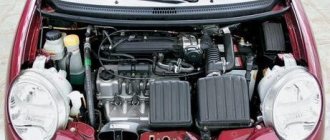
You also need to pay attention to diagnosing the performance of the generator unit. If this device is not working properly, it will not be able to charge the car battery when the engine is running.
To diagnose the generator, you will need a tester - a multimeter; you need to switch it to ohmmeter mode, and then perform the following steps:
- The tester probes are connected to the battery observing polarity.
- The engine starts, after which it is necessary to set the crankshaft rotation speed to medium, turn on the music and optics. This way you can create operating conditions for the motor, under which the battery voltage is measured.
- After this, it is necessary to take readings from the tester. If the generator unit is in working condition, the voltage parameter at the battery terminals should be about 13.5-14.5 volts. If this value is lower, then the device needs to be checked in more detail (video author - Dmitry Pristrom).
Wiring diagrams Daewoo Matiz
All diagrams are in color and are of good quality.
A little history of Daewoo Matiz This car model has been produced for a year. To date, the third generation of Daewoo Matiz M has already been released. Matiz of the first generation M? M and second M? M Hatchback has 5 seats.
All models are equipped with a manual gearbox, and the consumer can choose the engine: After a slight restyling of the car, the M model was released in China and was called Chevrolet Lechi.
Video about the crash test of Daewoo Matiz 1.2 and 3rd generation, respectively - and year: Electrical diagrams of Daewoo Matiz: Numbering of contacts in electrical connectors: Electrical diagram of engine starting and generator connections 0.8 l engine: Engine control system 1. Electrical diagrams Daewoo Matiz 0 engine management systems.
Electrical diagram of Daewoo Matiz: Connections of the relay and fuse box located under the hood of the car, engine 1.
Connections of the relay and fuse box located in the passenger compartment of the car engine 1. Connection diagram of the relays and fuses engine 0. Wiring diagram of the Daewoo Matiz 1.0 liter instrument cluster: Connections of the instrument cluster of a car with a 0.8 liter engine: Turning on the panel backlight and instrument cluster 0 .8 l: Turning on the headlights and the headlight control 1.0: Electrical circuit for turning on the headlights of a Daewoo Matiz 0.8 l: Turning on the headlight control for the car 0.8: Switching on the fog lights and fog lamps in the rear light 1.0: Electrical diagram of Daewoo Matiz 0.8 liter for turning on fog lights and fog lights in the rear light: Turn indicators and hazard warning lights, electrical diagram: Diagram of operation of the interior and trunk lighting bulbs, as well as switching on the electric windows of the front doors: Electrical diagram of the windshield wipers and washers and rear window of Daewoo Matiz: Heated rear window glass and diagram of the cigarette lighter and clock: Daewoo Matiz 1.0 car air conditioner and fan: Wiring diagram for turning on the air conditioner and fan of Daewoo Matiz 0.8 liter: