02/16/2021 5,664 Daewoo
Author: Ivan Baranov
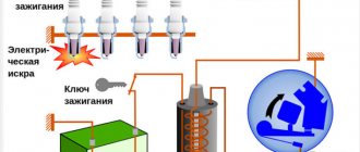
As you know, the ignition distributor or distributor is one of the main components in the ignition system of any car. If this unit fails, the driver will know about it in any case, since it will be impossible to start the engine. In this article we will tell you how to check the Matiz distributor and how to repair this device.
[Hide]
Why are timing marks needed?
The timing marks are marks along which the timing belt is adjusted, as well as the drive belt is replaced.
This element is quite important because it directly affects the operation of the power unit. What happens if, when replacing a belt, you set the marks incorrectly or don’t set them at all? In this case, you can knock down the gas distribution mechanism, which will lead to many problems. Namely:
- Since the gas distribution has been disrupted, the injection and release of exhaust gases will be carried out incorrectly. Subsequently, the engine may start to stall, stall, fail to start, or consumption may increase. In turn, this can lead to consequences, such as increased wear, burnout of the valve mechanism and piston group, and others.
- Everyone remembers what happens when the timing belt breaks - valve bending. This happens because the gas distribution process is disrupted and the pistons hit the valves, which are subsequently deformed. The exact same principle works in this case. A broken timing mechanism will cause the piston group to fight against the valves, which will simply deform them.
- Shifting the timing mark when changing a belt or adjusting will result in fuel being injected too early or too late. The consequence of this may be flooding of the spark plugs or suction of exhaust gases into the combustion chamber.
In addition to the induced consequences, others may also arise, which can also lead to increased wear and tear of power unit parts or other problems.
If there is no spark when starting the engine.
First, let's look at how to check for a spark. Modern ignition systems have a secondary voltage of about 25-32 kV; in early systems the voltage did not exceed 15 kV. The gap during testing should not exceed 10 mm; with a larger gap, the switch may fail. Reasons for the lack of spark on a 16-valve engine, as on most modern injection engines. You can read in detail in the article “Injection engine does not start.”
Troubleshooting on an 8-valve engine is somewhat different and first of all you need to check the presence of power on the positive wire of the distributor and the integrity of the control wire from the distributor to the coil. The most loaded part of the ignition system is the switch and it is also the cause of the malfunction in most cases. It is quite difficult to check it; for this you will need a stand that simulates the operation of the ignition system, or an oscilloscope. Usually it is simply replaced with a known good one. The ignition coil fails extremely rarely, but for some reason, when searching for a lost spark, it is the first to be replaced. Checking the coil is quite simple; you need to measure the resistance of the windings. The measurement value of the primary winding is approximately 0.4-0.6 Ohm, and the secondary winding is about 8.3-8.5 kOhm. When measuring, it is worth taking into account the magnitude of the instrument error. The most common malfunction is a break in the secondary winding, in which case the resistance value will differ significantly from the nominal value.
To check the inductive sensor of the distributor, it is also enough to check its resistance value, which is approximately 400-500 Ohms. A large deviation from the norm indicates a break in the coil and it must be replaced.
admin 12/24/2016
“If you notice an error in the text, please highlight this place with the mouse and press CTRL+ENTER” “If the article was useful to you, share the link to it on social networks”
Daewoo Nexia ignition system
The ignition system of the Daewoo Nexia depends on the type of engine. On 8-valve engines, non-contact ignition with high-voltage centrifugal distribution is used. The 16-valve engines use a microprocessor ignition system with static high-voltage distribution.
Ignition system of Daewoo Nexia with 8 valve engines
This ignition system, as stated above, is non-contact with a centrifugal distributor. That is, the system must necessarily consist of a distributor, a switch and an ignition coil. The distributor is attached to the cylinder head and connected to the camshaft.
When purchasing parts for the distributor, I noticed that almost everywhere they sell a “Hall sensor” for distributors. The same statement is found on many sites on the Internet. But this statement is not true.
An inductive sensor is installed in the distributor, that is, a coil on a magnetic circuit in the middle of which a permanent magnet rotates. In this case, an alternating voltage of approximately 3V is induced in the coil.
This signal is fed to a switch, which converts the signal and, depending on it, controls the ignition coil. The switch is located inside the distributor.
Ignition system of Daewoo Nexia with 16 valve engine
Unlike the ignition system, the 8-valve engine does not have a distributor. High voltage is generated by two ignition coils controlled by a two-channel switch, made in the same housing with the coils.
Self-diagnosis and repair of distributors on Daewoo cars
Typical faults
If the distributor in a Daewoo Nexia car fails, the symptoms will be as follows:
- The car will jerk while driving.
- The engine may not start at all.
- When the driver presses the gas pedal, detonation may occur - a metallic knock from under the hood.
- The vehicle as a whole picks up speed rather poorly.
- Fuel consumption may increase.
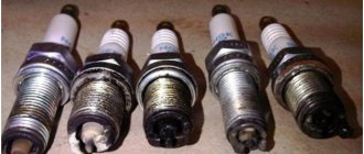
Of course, if such symptoms appear, this does not mean that the problem lies in the distributor. However, if such signs appear, you should first check the spark plugs, the condition of the high-voltage wires that are connected to them, as well as the distributor itself.
Wiring diagram for daewoo nexia and matiz with a description of electrical equipment, searching for problems with wiring
If we talk directly about breaker malfunctions, then it is characterized by the following breakdowns:
- burnout of the runner;
- The distributor cover does not work, in particular, the contacts are burnt out;
- Hall sensor failure;
- the bearing element of the sensor is jammed or it is worn out and it’s time to change it;
- presence of damage or cracks on the cover;
- The Hall controller is disconnected or its contact with the wiring is poor;
- Motor fluid got into the distributor (the author of the video is Nail Poroshin).
How to check the device for serviceability?
The distributor diagnostic procedure is carried out as follows:
- First, you need to look at the engine in the dark to see if there are sparks in the distributor area. If there is, then this indicates a violation of the insulation. Remember to always keep the lid dry.
- Also diagnose the integrity of the wiring - whether the contacts are intact or not. The terminals themselves on the cover must not be removed.
- Remove the cover and diagnose the integrity of the slider. After removal, look at the inside of the cover to see if the contacts are intact.
- Try shaking the slider - any gaps are eliminated. If there is play, there will be an unstable gap in the contacts.
- Diagnose the wear and gap in the contacts - it should be no more than 2 mm, the less the gap, the better. If the contacts are burnt, they must be cleaned.
- Then connect the lamp to the side terminal of the distributor and turn on the ignition. Try turning the engine manually - at this time the lamp should blink and go out at regular intervals. If this does not happen, then most likely there is a short circuit in the system, as a rule, this is due to the fact that the moving part touches the housing itself (the author of the video about diagnosing the distributor cap at home is Auto Electrics HF).
Replacement instructions
Let's consider the process of replacing the distributor using the Daewoo Matiz model as an example:
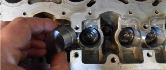
Disconnect the battery and unscrew the bolts of the air intake, as well as the air filter element. Dismantle it. Next, disconnect the hose that connects the throttle to the filter and dismantle it. Disconnect the high-voltage cables from the device cover, but before doing so, mark their position. Remove the block with wires from the breaker. Using a 12mm socket wrench and a small ratchet with an extension, remove the screws of the breaker device. Place a rag under it, as some of the engine fluid may come out when dismantling the device. Twist the assembly a little and remove it.
When removing, pay attention to the limit switch - its antennae are installed with a slight offset, and not in the center, so when installing a new device, install the limit switch in the same way. Install the new distribution unit, tighten the lower fixing screw, but not completely. Do the same with the top bolt. Reconnect the high-voltage cables, observing the order in which they are connected.
Further assembly steps are carried out in reverse order. After installing the unit, it is necessary to adjust the idle speed and ignition. If the ignition is set incorrectly, the symptoms will be the same as if the distributor breaks down.
Video “How to clean contacts in a Matiz distributor”
The video below provides detailed instructions for cleaning the contacts in the distributor device at home (the author of the video is the Diman and Automobiles channel).
Typical faults
If the distributor in a Daewoo Nexia car fails, the symptoms will be as follows:
- The car will jerk while driving.
- The engine may not start at all.
- When the driver presses the gas pedal, detonation may occur - a metallic knock from under the hood.
- The vehicle as a whole picks up speed rather poorly.
- Fuel consumption may increase.
Of course, if such symptoms appear, this does not mean that the problem lies in the distributor. However, if such signs appear, you should first check the spark plugs, the condition of the high-voltage wires that are connected to them, as well as the distributor itself.
If we talk directly about breaker malfunctions, then it is characterized by the following breakdowns:
- burnout of the runner;
- The distributor cover does not work, in particular, the contacts are burnt out;
- Hall sensor failure;
- the bearing element of the sensor is jammed or it is worn out and it’s time to change it;
- presence of damage or cracks on the cover;
- The Hall controller is disconnected or its contact with the wiring is poor;
- Motor fluid got into the distributor (the author of the video is Nail Poroshin).
( 2 ratings, average 4.5 out of 5 )
Repair and replacement of the contact group of the Daewoo Nexia ignition switch, how to check for problems
The car of the Korean manufacturer is popular among car enthusiasts. Daewoo Nexia is a convenient and practical vehicle for the city.
The design and principle of operation of the climate system in a daewoo nexia car
But, unfortunately, there are no ideal cars; each has its own weak points. In Nexia, this is a group of contacts in the ignition switch. It often breaks down.
In the article we will look at why the contact group burns, how to repair and replace, what to do to prevent the part from burning in the future?
What does the ignition switch contact group look like?
This part is located in the ignition switch. When you turn the key, it is responsible for supplying current to the starter and providing power to other elements of the car: the radio, the heater fan. The Daewoo Nexia uses a design solution that, according to experts, can hardly be called successful.
Let's take a closer look at the contact group. Electrical contacts are placed in a plastic case made of two parts; they are switched depending on the position of the key.
The contact group in a Korean car often burns out due to an unsuccessful design decision
Nexia’s group has 5 conclusions:
- “30”—power is supplied from the battery;
- “15” - ignition circuit;
- “15a” - heater fan circuit;
- “50” — output to the starter;
- “Ka” or “Kb” is the circuit of the original radio.
A strong current passes through the ignition switch. As a result, the wiring becomes very hot and the contacts melt. A large load occurs when the engine starts, the pin marked “30” suffers the most. First of all, it doesn’t hold up; the plastic case near the contact melts.
Due to the high current that passes through the group of contacts in the ignition switch, the contacts become very hot and the plastic housing melts
In most cases, burnout of the contact group manifests itself as follows: after turning the key in the lock, the starter does not turn. When driving, it manifests itself as follows: the engine suddenly stalls, the instrument panel goes dark and the smell of burnt plastic appears in the cabin. The second sign of a breakdown is a non-working standard radio.
VAZ 2110 or Nexia: making a choice
It cannot be said that the starter does not spin and the car radio does not work only because of the contact group, but in 90% of cases for the Daewoo Nexia the symptoms are exactly the same.
How to check and make repairs
Any car enthusiast can check the serviceability of the group of contacts in the ignition switch. Performance is determined by the appearance of the plastic case and the presence of carbon deposits on the contacts inside the group. To get to the part, it is enough to arm yourself with a Phillips and straight screwdriver.
We remove the plastic under the steering wheel, it is secured with screws.
First you need to remove the protective plastic under the steering wheel.
Disconnect the connector chip from the contact group.
The connector can be easily removed from the group of contacts with a simple screwdriver
Unscrew the small screw with a thin flat screwdriver. It secures a group of contacts in the ignition switch housing.
Using a thin flat screwdriver, unscrew the screw that secures the group in the ignition switch housing
Use a screwdriver to pry up the contact group and separate it from the ignition switch. After dismantling, we carefully inspect the case, paying special attention to the contacts. If the plastic has melted near them, then it is necessary to replace the part with a new one. We install the new spare part in the reverse order.
If the case is not damaged, be sure to inspect the internal contacts. To do this, carefully disassemble the case. If carbon deposits are found, remove it with a sharp knife or screwdriver. This temporary procedure will help along the way. As soon as possible, contact an electrician at a service station or replace the contact group yourself.
It should be noted that replacing the contact group with a working one helps for a while. For high-quality repairs, it is necessary to eliminate the cause of burnout: reduce the current load on the contacts. You can strengthen the weak point of the Daewoo Nexia by installing additional relays according to the diagram:
When using two relays, the load on a group of contacts is halved
This method will help extend the service life of the contact group by more than 2 times. Anyone can improve the electrical ignition circuit of a Korean car.
Video: Replacing the contact group on the Daewoo Nexia
To fully understand the process of replacing a group of contacts in the Daewoo Nexia, watch the video:
Repairing the contact group on a Daewoo Nexia car yourself will not be particularly difficult. Additional difficulties will arise if the wiring needs to be replaced. The wires going to contacts “30” and “50” often melt. If possible, relieve the contact group. This will protect the car from fire and extend the life of the part.
Diagnosis of distributor cover faults and their elimination
The distributor is a unique mechanism designed to determine the moment when high-voltage pulses begin to form in the ignition system. This device is used to distribute electric ignition among the cylinders of two types of gasoline internal combustion engines - injection and carburetor.
The distributor, by its nature, differs from other components in that its structure has a fairly large number of parts that wear out quickly. But the condition of this mechanism has a direct impact on the efficiency of the engine, as well as its starting characteristics. In addition, how efficiently the distributor works also affects the overall dynamics of the car and the toxicity of the exhaust.
As for the functions of this mechanism, there are two main ones:
- Interruption of the primary ignition circuit - in this way, the distributor provides current fluctuations in the primary winding of the coil, as a result of which a high level voltage appears in the primary part.
- Distribution of energy between the cylinder spark plugs in the required quantity and sequence.
The described mechanism is also indispensable because in its structure it has a number of mechanisms whose task is to change the ignition timing, which depends on the operating mode of the engine.
Symptoms of a problem
Before you begin repairing the mechanism being analyzed or the distributor cover, naturally, you should carefully check it. This will help you find out the specific cause of the problem and how to deal with it.
There are certain signs that indicate a malfunction in the distributor. Their list included the following:
- While driving, the car jerks unusually and abnormally.
- The engine will not start.
- As the engine accelerates, the piston pins begin to knock.
- The car picks up speed very slowly.
- Fuel consumption increases significantly.
Naturally, the presence of any of the above symptoms does not yet give the right to say that the problem lies specifically in the ignition distributor. But if any of them is identified, you should begin to “sound the alarm” and, preferably, prepare to repair the distributor.
The list of the most common distributor malfunctions includes:
- A runner who went broke.
- Burnt contacts that are located in the distributor cover.
- Hall sensor failure.
- The Hall sensor bearing is stuck or loose.
- The appearance of cracks in the lid.
- The Hall sensor plug has poor contact.
- Oil gets into the distributor despite the presence of a protective cap.
It should be noted here that all types of the above problems with the distributor imply the replacement of faulty parts, in addition to the last two points.
So, the car owner has identified certain malfunctions in the operation of the distributor and is ready to begin repairing this unit on his own. The first thing you need to know in this case is how to properly remove and install the distributor back. I recommend following these instructions:
- To begin with: check if sparks are visible when the engine is running. This can usually be done in the dark. If sparks are visible, this gives rise to an insulation violation. Also, the lid must be dry and clean, and it is prone to burning. In addition, I advise you to check the wire connections, that is, the integrity of the contacts. Therefore, the terminals in the cover should not be removed, at least without much effort.
- After completing the basic checks, remove the negative cable from the battery terminal.
- Disconnect the high-voltage wires and vacuum hose from the distributor.
- Remove the cable from the throttle valve drive.
- Together with the wires and studs, remove the bracket that holds the wires. To do this, unscrew the nut and under no circumstances lose it.
- Apply special marks to the housing, distributor cover and auxiliary device drives, which will help maintain the starting ignition timing during further installation of the described mechanism in place. Otherwise, it will need to be adjusted.
- Using a screwdriver, press the connector lock to which the drive harness is connected and pull out the drives.
- Pull out the rubber plug located in the clutch housing.
- Rotate the crankshaft until the piston of the first cylinder is at the top dead point. In this case, the flywheel mark should coincide with the middle division on the housing scale.
- Unscrew the nuts and remove this device together with the distributor cover.
- Installation is carried out in reverse order. Here we should remind you of the mandatory check of the alignment of the marks and the ignition timing.
The car owner should know that each wire on the distributor cover is installed in a certain sequence, which depends on the operation of the cylinders.
So, of all of them, only the first one is indicated, and the rest must be installed by the driver himself, and this must be done counterclockwise.
Another mandatory factor when carrying out this procedure is that the car enthusiast’s view should be from the side of the antifreeze tank, made of plastic.
An equally important point: if there is a need to replace the cover or slider, then dismantling the distributor itself is no longer required.
So, repair of the ignition distributor-distributor takes place in the following stages:
- Disconnecting high-voltage wires and removing the distributor from the vehicle.
- Removing the cover and carefully inspecting it. The fact is that it can be pierced (this is manifested by the presence of a thin dark strip), and this can only be eliminated by replacing it with a new one. Also, the central contact in it may fall out (it is also called a coal), which can be corrected in the same simple way - by replacing it with a new one.
- Checking the slider, which will also need to be replaced if there is a blown fuse and dark stripes, rust, or traces of burning.
- Remove the dust shield: remove the low voltage terminal by unscrewing the screw that secures it, then use a screwdriver to open the claws of the holder and remove the wires from it. Next, unscrew the two screws that secure the Hall sensor support plate and remove the latter. After this, pull out the retaining ring from the plate pin, which may require considerable force. Unscrew the screws that secure the vacuum corrector, then use a screwdriver to pull out its rod - now it can be completely removed from the distributor. The final step is to pull out the support plate and check the condition of its bushing. Ideally, there should not be any tears on it, and there should be no noticeable wear on it. Otherwise, there will be a need to completely replace this element.
- Remove the snap ring, the pressure pin that secures the coupling. If the sealing ring is torn, has lost its former elasticity or is completely worn out, urgently replace it. Drive the pin out of the coupling, remove it and the adjusting washers. This element needs to be replaced if its spikes are “licked off”.
- Remove the centrifugal regulator and roller. If backlash, wear, potholes, burrs, non-free rotation of loads, etc. are detected. – replace the entire distributor body.
Repair of the distributor, despite the fact that it is considered a complex part and no less capricious, can be carried out on your own. Therefore, I advise you not to be afraid and try to complete this process, while being sure to follow the given instructions.
The starter does not turn on the Nexia. Looking for reasons together
When we turn the ignition key to the starting position, we do not hear any reaction from the starter - a fairly common breakdown for Nexia. Moreover, in 80% of cases it is not the starter that is to blame, but first things first. First of all, we check the starter for performance. To do this, take a powerful short screwdriver and begin diagnostics.
- Turn on the ignition, set the gearbox to neutral and tighten the handbrake.
- Open the hood and look for the starter.
We find the starter.We clean the terminals from dirt.
- We see three terminals - one on top and two large ones on the bottom. The upper terminal is responsible for the operation of the solenoid relay, which starts the starter motor.
- To check the retractor relay, we close the upper and positive (large, farthest from the starter housing) terminal, red arrows in the photo.
The relay should operate, the gear should engage with the flywheel, and the power contact should start the electric motor. That is, if these two terminals are closed when the ignition is on, the starter should start the engine. If the solenoid relay does not operate, the starter needs repair. Checking the solenoid relay. - If this does not happen, we close the two lower terminals, green arrows in the photo.
The starter motor should start without engaging the flywheel crown. If the electric motor is silent, then we are dealing with a short circuit in the windings or other malfunctions of the rotor or stator of the motor. Checking the starter motor.
Contact group - the cause of starter failure
If the starter works by itself, as the first test showed, then with a high degree of probability the fault can be caused by the contact group of the ignition switch. The fact is that when designing the electrical circuit, the engineers did not take into account the high load on the ignition switch contacts. When starting the engine, voltage from the battery is supplied directly to the contact group and when the starter is turned on, a large current passes through the contacts, they heat up and burn out over time.
How to prevent breakage of the contact group
Of course, you can simply replace the contact group with Nexia, but there is no guarantee that the story of contact burnout will not repeat itself. To avoid problems occurring in the future, it is necessary to unload contacts 15 and 30 of the contact group. To do this, it is necessary to install an unloading relay between these contacts. A regular starter relay from a VAZ 2108, connected according to the circuit between pins 15 and 30, is suitable.
New contact group.
Starter relay - 30 A (VAZ-2108) or 50 A (VAZ-2110).
Contact terminals.
Let's understand the connection diagram: you can relieve not only the ignition circuit (pins 30 and 15), but also the starter circuit (pins 30 and 50).
We connect the wires to the terminal block.
We get to the ignition switch by removing the steering column covers.
We assemble an electrical circuit.
If a situation arises when the starter does not turn, check the voltage at the battery terminals and, if necessary, charge it. In addition, it is useful to check the contact density on the positive terminal of the starter itself. The battery terminals are cleaned and lubricated with conductive lubricant, the contact of the positive wire is cleaned and tightened tightly. This way you can avoid problems with starting the engine in the future. Instant launches and sunny roads to everyone!
Replacement timing
Manufacturers recommend replacing worn parts of the timing mechanism drive with a mileage of no more than 50 thousand kilometers. Most owners follow this recommendation, but there are exceptions.
The service life of the belt depends not only on the manufacturer of the spare part, but also on the operating conditions of the vehicle and the technical condition of the engine. The condition of the belt is adversely affected by technical fluids that can get into its operating area. If even the slightest leaks of engine oil are noticed, they are immediately eliminated and the belt is replaced with a new product.
Replacing the distributor on a Daewoo Matiz with your own hands
in Autoelectrics 01/17/2018 10,
As you know, the distributor or ignition distributor is one of the main elements in the ignition system of any car. If this unit breaks down, it will be impossible to start the engine. In this article, we will look at the procedure for replacing a distributor with your own hands, using the Daewoo Matiz model as an example.
Distributors for Matiz are produced by two companies DELPHI (DAC) and MANDO. And, if you change the entire ignition distributor breaker, then it doesn’t matter which manufacturer’s device you install on your car. But if there is a need to replace the rotor (runner) of the distributor or its cover, then you need to be more careful. The distributor cap from MANDO will not fit the ignition distributor from DAC and, on the contrary, the distributor cap from DAC will not fit the device from MANDO. The picture is similar with rotors (runners).
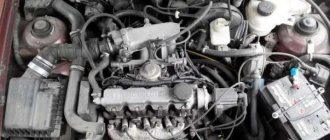
Engine Daewoo G15MF 1.5 l/75 l. With.
Contents The prototype of the G15MF engine was the C16NZ power drive from Opel. Korean engineers made the following changes to the design of the German engine:
- the cooling system outlet pipe is installed in the rear cylinder head plug;
- the configuration and size of the combustion chamber has been changed;
- original oil pump used;
- the shape of the pistons has undergone changes, the diameter of the cylinders has been reduced;
- The ignition system has been modified for the G15MF configuration.
ICE Daewoo G15MF
In 2002, during the restyling of Daewoo Nexia, the engine was improved to 130 Nm and 85 hp. With. by increasing the piston stroke to 81.5 mm, installing a 16-valve cylinder head with two camshafts according to the DOHC scheme. However, this internal combustion engine was assigned a new index A15MF, and its production was discontinued in 2008 simultaneously with the G15MF, since they did not meet the Euro-3 environmental protocol.
Improved version of A15MF
What does the ignition switch contact group look like?
This part is located in the ignition switch. When you turn the key, it is responsible for supplying current to the starter and providing power to other elements of the car: the radio, the heater fan. The Daewoo Nexia uses a design solution that, according to experts, can hardly be called successful.
Let's take a closer look at the contact group. Electrical contacts are placed in a plastic case made of two parts; they are switched depending on the position of the key.
The contact group in a Korean car often burns out due to an unsuccessful design decision
Nexia’s group has 5 conclusions:
- “30”—power is supplied from the battery;
- “15” - ignition circuit;
- “15a” - heater fan circuit;
- “50” — output to the starter;
- “Ka” or “Kb” is the circuit of the original radio.
Typical unit malfunctions and ways to correct them
The 8-valve Daewoo Nexia model is practically non-separable, which is why most faults cannot be eliminated. In most cases it will need to be replaced.
The most common problem is sticking of the primary or secondary winding. The occurrence of such a problem can be detected by too much voltage at the output of the part.
Also, problems can arise due to breakdown of the ground, usually through the mounting bracket to the body. In this case, it is also necessary to replace the device.
The video below shows the process of breaking through to ground (the author of the video is V pandex).
Repair of ignition distributor Daewoo Nexia
Checking the ignition coil
| 1. OHMMETTER 2. TERMINALS C AND TAC 3. OHMMETTER 4. TERMINAL B 5. OHMMETTER |
| General information |
| 1. Check the ignition coil windings for breaks and short to ground. |
| Step 1. Switch the ohmmeter to the coarsest range. The measured resistance must be very high (“infinite”). Otherwise, replace the coil. |
| Step 2. Switch the ohmmeter to the most sensitive range. The measured resistance should be very small (close to zero). Otherwise, replace the coil. |
| Step 3. Switch the ohmmeter to the coarsest range. The measured resistance should not be very high as in step 1. If not, replace the coil. |
Checking the magnetoelectric sensor coil
| 1. ELECTRONICS MODULE 2. MAGNETOELECTRIC SENSOR COIL ASSEMBLY 3. SENSOR COIL WIRES DISCONNECTED FROM ELECTRONICS MODULE 4. OHMMETER 5. OHMMETER |
| General information |
| 2. Remove the rotor and disconnect the sensor coil wires from the electronic module. |
| 3. Connect an ohmmeter in series using methods 1 and 2, see fig. Checking the magnetoelectric sensor coil. |
| 4. Check the coil for a break. |
| Step 1. The measured resistance should be very high (“infinite”). Otherwise, replace the coil. |
| Step 2: The measured resistance should be between 500 and 1500 ohms. If the resistance value is outside this range, the coil should be replaced. |
Removing the drive clutch pin
| General information |
| 5. Remove the spring. Mark the drive coupling and roller to facilitate subsequent assembly. Support the coupling on the Y-shaped stand. Knock out the pin and remove the coupling. Remove all burrs with a file and remove the roller. |
Removing the magnetoelectric sensor coil
| General information |
| 6. In order to dismantle the coil, you must first remove the thin spring ring. |
| 7. Remove the coil by lifting it up. |
Removing the electronic module
| General information |
| 8. Disconnect the electrical connector of the module, remove the two screws and remove the module. Test the module using test equipment. |
| 9. Wipe the distributor base and module clean and lubricate the module installation site with silicon-containing grease to improve heat dissipation from the module. |
| 10. Install and secure the module. Connect the connector. |
| 11. Install the sensor coil and thin snap ring. |
| 12. Assemble the roller, coupling and install the pin. |
| 13. Rotate the roller to check that it rotates freely. |
| 14. If the roller is caught, loosen the sensor coil, remove the jam and secure it again. |
| 15. Install the rotor and cover. |
Video about “Repairing the ignition distributor” for Daewoo Nexia
distributor repair/ignition installation daewoo nexia
distributor repair/ignition installation daewoo nexia
Distributor cover Daewoo MARRIAGE or made in the basement flamma pl Nexia
Distributor cover Daewoo MARRIAGE or made in the basement flamma pl Nexia
Engine operation on Daewoo Nexia, distributor
Engine operation on Daewoo Nexia, distributor
Removing the distributor for Daewoo Matiz
Let us remind you that the distributor on the Daewoo Matiz is mounted not in the classic vertical position, but in a horizontal one. So let's get started:
- lift the hood;
- disconnect the positive terminal from the battery and unscrew the 3 bolts of the air intake and air filter element. Dismantle it.
- remove the pipe (hose) connecting the throttle and the air filter, before removing it, disconnect the two small pipes that go into it;
- disconnect the high-voltage cables from the ignition distributor cover, but before doing this, mark their position, for example, with a marker;
- remove the block with wires from the breaker;
- Using a 12mm socket wrench, unscrew the ignition distributor breaker bolts and pull them out;
- While turning the ignition distributor switch slightly, pull it towards you. When the distributor is pulled out, engine oil (approximately 100 grams) may pour out; to avoid spilling the oil, you can lift the car with a jack so that the oil flows to the right side of the engine. When dismantling the ignition distributor, pay attention to the end of the distributor - its antennae are not in the center, but with a slight offset. Therefore, when mounting a new device, place the end switch in exactly the same position;
- install the new switchgear, tighten the lower mounting bolt, but not completely. Do the same steps with the top screw.
- Reconnect the high-voltage cables, following the order in which they are connected. Subsequent assembly steps are performed in reverse order. After the distributor is installed, it is necessary to adjust the engine idle speed, as well as the ignition. If the ignition is set incorrectly, the symptoms will be the same as with a faulty distributor. If everything was done correctly, the car will function properly.
However, to be absolutely sure, visit a service station and let specialists accurately check the ignition timing, which may have gone astray when installing the distributor. The car may lose power if it consumes more gasoline.
Distributor
Sometimes, quite suddenly, Nexia refuses to start with the key. In this case, the engine starts quickly “from the pusher”. This behavior of the power plant directly indicates a malfunction in the ignition system. The cause of problems with starting with the key in pre-restyling models is usually found in the distributor.
Distributor Daewoo Nexia 1.5 (8 valves)
Specialists from the South Korean company Daewoo thought for a long time about how to solve the problem of the distributor literally crumbling over time, and as a result they not only radically changed the ignition system of the 8-valve internal combustion engine, but also the fuel injection and cooling systems. The modernization led to the fact that instead of a distributor, an electronic module appeared in the ignition system.
Diagnosis of distributor cover faults and their elimination
The distributor is a unique mechanism designed to determine the moment when high-voltage pulses begin to form in the ignition system. This device is used to distribute electric ignition among the cylinders of two types of gasoline internal combustion engines - injection and carburetor.
Maintenance schedule G15MF 1.5 l/75 l. With.
Despite the declared service life of 250,000 km, the manufacturer recommends servicing the G15MF engine during maintenance according to the following schedule:
| Consumable item or service step | Time (year) or mileage (1000 km), whichever comes first |
| Timing drive | 7/100 |
| Battery | 2,5/40 |
| Adjusting the thermal clearance of valves | 2/15 |
| Checking and cleaning the crankcase ventilation | 2/35 |
| Attachment belts | 4/50 |
| Inspection and cleaning of the fuel line | 2/40 |
| Motor oil | 1/10 |
| Oil filter | 2/20 |
| Air filter cartridge | 2/40 |
| Fuel filter | 4/40 |
| Checking and replacing heating/cooling hoses | 3/30 |
| Antifreeze | 2/40 |
| CO and oxygen sensor | 10/100 |
| Spark plug | 1 – 2/20 |
| Exhaust tract | 1/20 |
The classic internal combustion engine design allows you to reduce operating costs and the cost of overhauls.
The procedure for connecting high-voltage wires on a Daewoo Nexia car
visibility
67220
archive
0
Attention!!! Emergency Note! For you, Nexia waters and Nexia lovers. If under the hood of your iron friend there is a four-cylinder, eight-valve engine with a volume of 1.5 L - G15MF with the good old ignition distributor (distributor), then this article will be useful to you
And it is especially useful for those happy owners of Daewoo Nexia cars who like to change high-voltage wires and spark plugs themselves. And it does it very quickly. So quickly that he forgets to remember in what order the high-voltage (HV) wires are connected to the ignition distributor))).
Common situation? And naturally, in such a situation, the busybody starts calling a car mechanic he knows. He talks about the embarrassment that happened to him and asks for help over the phone.
Now to the point. The order of connecting high-voltage wires on an 8-valve Daewoo Nexia with an ignition distributor (distributor) is 1-3-4-2. The report is carried out from the contact for the wire of the first cylinder, counterclockwise.
All that remains is to determine which contact of the distributor cover the wire of the 1st cylinder is connected to. Therefore, you need to find the arrow on the distributor body (ignition distributor) (photo 1). Found it? Here, this arrow points to the contact for the wire of the first cylinder. Then everything is simple - look at photos number 2 and 3.
The high voltage wire from the ignition coil is connected to the contact located in the center of the distributor cap.
Daewoo Nexia — Disassembly and assembly of distributor
A small addition, so that there are no misunderstandings: on the Daewoo Nexia engine, the cylinder counting order is carried out according to the most common principle, from left to right, from the timing belt (photo 4).
This is all! I think you will no longer have problems connecting high-voltage (armor) wires))). For yourself, you can, and probably even need to, number the contacts on the distributor cover with a marker.
So that in the future, when replacing wires, you don’t waste time and rummage through the farthest corners of your brain in search of the numbers you once memorized.
When using an article or photographs, an active direct hyperlink to the website www.avtorem.info is required!
Problems with power windows
The build quality of the Daewoo Nexia, unfortunately, very much depends on the factory at which the car was assembled. Most often, problems with window regulators arise on Russian-assembled Daewoos, and the components supplied to both Uzbekistan and Poland are, apparently, exactly the same. However, if problems arise with the window regulators, you need to make sure that the problem is in the electrical part. If everything is fine with the mechanics, then you should check the fuse in the mounting block.
If everything is in order with it, then most likely it is in the lift control unit. The main unit is located in the driver's door armrest. The most likely failure is failure of the control keys or lack of contact in the control unit. The fact is that the door is constantly subject to vibration, so due to poor quality assembly, the contacts may simply come off.
We recommend: Replacing the oil filter on Lifan X60
Checking the fuel pump
You can check the operation of the fuel pump yourself; it is not difficult to do. After gaining access to the fuel pump, you can begin to diagnose it. On command, the assistant turns on the ignition (for a couple of seconds), after which a sound should appear indicating that the pump is working.
In addition, it will be necessary to check the resistance of the fuel supply element to the engine. If at the moment of starting the engine you do not hear any signs of its operation, this must be done. To do this, connect the multimeter to the power contacts of the fuel pump. After diagnosis, resistance measurements must be compared with the manufacturer's data. If the figures obtained differ greatly from the manufacturer's specifications, then most likely the fuel pump has completely failed.
Wiring diagrams
Using the following wiring diagram, you can determine the locations of connectors and ground contacts, which can cause interruptions in the operation of devices when they are loosened.
Electrical connectors are marked in yellow and begin with the letter X. Ground wires and body ground contacts are marked with blue dots and numbered.
Ground contacts
1 - in the central part of the steering column 2 - near the battery 3 - not used 4 - on the top of the engine cylinder block 5 - in the trunk 6 - under the driver's seat B - direct contact of the assembly housing with the car body.
Design Features
The one and a half liter single-shaft in-line petrol engine G15MF was created before the advent of Euro-2 standards, so the design feature is an extremely simple exhaust tract design without a catalyst and CO probe. The remaining nuances of the internal combustion engine are:
- modernization of the injection system - injection here is distributed, but simultaneous, regulated by a potentiometer, as on domestic Ladas;
- modification of the combustion chambers - these engines have a smaller cylinder diameter compared to the prototype, and a dome-shaped chamber, partially extended into the piston;
- according to the manufacturer, oil consumption is within 300 g/1000 km, and gasoline consumption is 8.8 l/100 km in the combined cycle;
- flat tooth timing belt from the leading brand Geitz with a service life of 200,000 km, although the safety of the valves is already ensured here, they cannot meet the pistons.
Cooling system
Timing belt G15MF
The gas distribution system is made according to the SOHC scheme with one camshaft. Compared to the sample, the volumes of the combustion chambers are reduced; power will be increased only in the next series of Daewoo engines - A15MF.
To increase the resource, the attachment is driven by a separate belt, the condition of which is recommended to be monitored every 20 thousand km, and changed after 50 thousand.
Exhaust system
After the introduction of Euro-3 and even Euro-4 regulations, Daewoo management continued to install these obsolete power drives on Nexia and Espero until 2008. Compactly located attachments do not interfere with major repairs, including on your own.
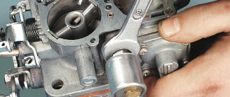
How to set the ignition on a Matiz, how to set it up
Many owners of a Matiz car from the Daewoo concern are faced with a problem: how to set the ignition on their pet if there are obvious problems with it? There are two ways to adjust the ignition on the Daewoo Matiz - with and without a strobe light.
Experienced motorists who are well versed in engine operation can adjust the ignition by ear and not spend money on purchasing a strobe light. Moreover, its accuracy is not always sufficient and there are tolerances on the car itself that distort the readings.
Action plan:
Set the engine to idle and move the distributor to “plus”. Move it in the opposite direction until detonation disappears at idle. Then, using the same actions, ensure the absence of detonation under sudden pressure on the gas.
Having secured the distributor, the car is rolled out onto a flat surface for inspection, the speed is increased to 50 km/h, gear 4 is engaged and the gas pedal is sharply pressed. If everything is adjusted correctly, detonation will last about 2 seconds, if it is absent or when it lasts longer, adjustment is required.
In cases where adjustment of the distributor is impossible due to reaching the extreme point (but the check shows that the ignition is not normal), it is necessary to check whether it is installed correctly and whether the crankshaft is aligned correctly. Try to align the distributor by turning one tooth in the direction of adjustment.
It is recommended to warm up the engine to operating temperature, then be sure to turn it off. We connect terminals A and C of the diagnostic connector using additional wire 1, or connect diagnostic tool 2 to the connector. The connector is located under the storage compartment.
Connection diagram
Connecting the strobe is carried out according to its instructions. Its sensor is connected to the high-voltage wire of the spark plug of the 1st cylinder. Then the engine starts. The strobe light is directed at the crankshaft pulley and the bottom of the timing cover.
1 — mark on the crankshaft pulley; 2 - timing angle scale on the timing cover
At the rotation speed corresponding to idle speed, the mark on the crankshaft pulley should be located exactly opposite the number “10” on the scale. This means that the lead angle is 10 degrees.
If the mark on the pulley deviates from the number “10”, adjustment of the advance angle is required. This is done by turning the distributor sensor housing clockwise for early ignition (value greater than 10) and counterclockwise for late ignition (value less than 10). Before starting the adjustment, be sure to stop the engine, be sure to turn off and loosen the sensor mounting bolts.
Change the angle of the sensor housing by rotating the housing
Change the angle of the sensor housing slightly by rotating the housing.
Having lightly secured the bolts, repeat steps 3–4 until the mark is positioned correctly.
Strobe assembly diagram
All elements are easy to find in any electrical goods store or even in the market. Instead of a lamp, it is better to use LEDs, which are found in any flashlight, and the entire circuit can be assembled in its body. In addition, you will need the simplest elements: a capacitor, a resistor, a relay, a transistor, a thyristor, a set of wires and clamps for battery power. The finished product looks like this.
Ready strobe
With it you can:
- adjust the ignition;
- check the spark plug or ignition coil;
- control the centrifugal and vacuum ignition timing regulator.
To check the correct adjustment, you must:
When the engine is warmed up and idling, press the gas pedal - there should be no failures in operation. Engage gear 4 when driving at a speed of about 50 km/h and apply gas significantly - detonation should be within 1-2 seconds.
Additional points:
- If the mark is constantly moving, it is worth checking the ignition distributor, wires, and coil. Perhaps there is a problem with them or there has been a wiring breakdown.
- You may also encounter a situation where everything is adjusted, but the car does not drive well. In such a situation, it is worth experimenting with setting the advance angle, perhaps it should be increased to 12 or even 25 degrees. If, with an increased angle at a speed of 50 km/h, the correct detonation is felt, there are no dips when pressing the gas, then everything is adjusted and selected correctly.
The ignition should be adjusted periodically, as the driver often does not notice the changes, which leads to engine wear and, as a result, expensive repairs.
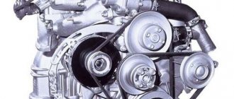
Timing timing marks for Daewoo Matiz
The process of operating a Daewoo Matiz car is impossible without replacing the timing belt after a certain mileage. If this condition is not met, the car owner may incur additional costs for major repairs of the car’s power unit. Replacing the belt is carried out by specialists at repair centers or independently. A guarantee of correct replacement of worn parts will be the installation of a timing mark.
About the engine
This “baby” is equipped with a gasoline engine with three cylinders; it has a working volume of only 800 cm3. Later, a liter power unit began to be installed on this car. The cylinder block is cast from cast iron, the cylinder head is made of aluminum alloy.
The operation of each cylinder is ensured by two valves. One each on the inlet and outlet channels. The engine power is 52 horsepower, which is more than enough for a small car.
The camshaft is located in the upper part of the cylinder head and is driven by a toothed belt drive.
To achieve high engine efficiency, a high degree of compression of the working mixture in the cylinders was selected. This was achieved by reducing the size of the combustion chamber, so if the belt drive breaks, the valves can meet the piston heads, which entails damage to the valves, pistons, connecting rods, and other parts of the crank mechanism. The car's operating instructions instruct owners to change worn timing drive parts with a mileage of no more than 60 thousand km.
Most owners complete this operation before the specified time. This depends on the operating conditions of the machine and its technical condition. In general, the engine has a long service life; it can last more than 200 thousand kilometers. The disadvantages of the engine include frequent distributor failures in the ignition system. After switching to an injection power system, such problems are no longer observed.
Why is it important to align the timing marks?
It is impossible to obtain full performance from the specified motor parameters without meeting certain conditions. One of them is the correct installation of valve timing. For this purpose, there are installation marks in the timing mechanism drive. Without them, it is impossible to correctly set the position of the camshaft relative to the crankshaft.
We recommend: Characteristics of the generator for the VAZ 2101, diagram of its connection, disassembly and assembly
If the position of the gear is shifted even by one tooth, the engine operating parameters will be greatly impaired. The ignition will be set early or late. This will affect not only the parameters of the motor, but also its technical condition. Carrying out the operation of installing the marks of the timing drive mechanism is not a difficult operation, but it requires care when performing it.
Camshaft marks
This part in the cylinder head is responsible for opening and closing valves in the intake and exhaust channels. Only complete filling of the cylinders with the air-fuel mixture and subsequent removal of exhaust gases will ensure that the specified engine parameters are obtained. The camshaft is driven by a pulley, which is driven by the rotation of a toothed belt. The correct installation of the pulley on the camshaft is ensured by a pin that will not allow it to rotate arbitrarily relative to the shaft.
In order for the cams to open or close the valves at the right time, installation marks are applied to the timing mechanism drive. The upper inner part of the protective roof has an arrow on the body, obtained by stamping during its manufacture. The camshaft pulley also has a mark, which is a mark on one of the teeth.
The pulley should be rotated until the mark and the arrow are directed exactly opposite each other. After this, you can continue working further. The mark is installed with the belt removed, otherwise the motor can be damaged.
In this case, you should carefully inspect the shaft seal; if engine oil leaks through the seal, it should be replaced with a new product.
Crankshaft marks
When the intake valve is open, the piston must be at top dead center so that when it moves down, the cylinder is filled with the working mixture. The piston is driven by the crankshaft through a connecting rod.
If the operation of the crankshaft is not synchronized with the camshaft, you can not only fail to start the car’s power unit, but also disable it for a long period. To prevent this from happening, installation marks are applied. The shaft pulley is installed through a key; it will not be able to rotate arbitrarily.
It has a tooth with a notch, which was obtained during the manufacturing process of the pulley.
The crankshaft oil seal protective cover also has an arrow-shaped mark obtained during casting. The shaft together with the pulley is rotated until the mark on the tooth is located exactly opposite the mark on the oil seal cover. This operation should be performed with the timing belt removed to prevent the pistons from meeting the valves. If there are traces of engine oil leaks on the oil seal cover, it should be replaced, otherwise the lubricant will accelerate the failure of the drive belt.
If the marks don't match
This problem can occur in two cases:
1. A new power unit is being assembled or after repair. 2. The drive belt has broken.
If in the first case there are no problems for the motor, then if the belt breaks while the engine is running, parts of the crank mechanism will break. To avoid such problems, you should carefully select spare parts, perform high-quality engine maintenance, and timely replace worn parts.
Which GDPs are better to choose?
When choosing a GDP, two key factors must be taken into account - their resistance and breakdown voltage. The lower the resistance, the better the electrical impulse will be transmitted, and the magnitude of the maximum breakdown voltage determines how resistant high-voltage wires will be to breakdowns.
The resistance value of products from different manufacturers differs from each other. As an example, we give you the resistance of the most popular types of GDP:
The products of the Czech company Tesla receive the largest number of positive reviews from the owners of the fourteenth. Their wires have optimal resistance and high breakdown voltage, and at the same time they are truly made to last - they do not tan or crack.
The cost of the Tesla GDP set is about 500 rubles, Cezar - 450 rubles, Ween - 270 rubles, Finwhale - 600 rubles, Slon - 500 rubles.