The “seven” transistor switch is one of the components of the contactless ignition system of this passenger vehicle. Beginner car enthusiasts who still do not understand many terms. looking for the place in the VAZ 2107 where the ignition switch is located.
Typically, the VAZ 2107 switch is located in the engine compartment of the car, often on the right mudguard, next to the Hall sensor and the ignition coil. To have an idea of what this gadget looks like and what to look for, you can look at a photo of the switch on our Internet portal.
What is BSZ and how does it work?
To successfully install and configure contactless ignition, it is advisable to understand the operating principle of the system, which consists of the following elements:
- Main ignition distributor (otherwise known as distributor). Inside it is installed a photoelectric Hall sensor, a vacuum drive for adjusting the advance angle and a so-called slider with a moving contact.
- A coil that produces a high voltage pulse. It has 2 windings: a primary winding, consisting of a small number of turns of thick wire, and a secondary winding, wound with a thin wire with a large number of turns.
- The electronic unit is a switch equipped with an aluminum cooling radiator. The latter plays the role of a fastening element.
- Spark plugs connected by high-voltage wires to the distributor.
- Wires for connecting elements to each other.
In the standard outdated VAZ 2106 systems, there was a contact group inside the distributor instead of a Hall sensor, and there was no switch at all.
Scheme of operation of the BZS VAZ 2107
The first contact of the coil is connected through the ignition switch relay to the generator, and the second to the control unit. Also, a high-voltage wire with a large cross-section goes from it to the distributor. There are 2 bundles of wires coming out of the distributor, connecting it to the switch and spark plugs. The system operates according to the following algorithm:
- After turning on the ignition by turning the key in the lock, a voltage of 12 V is applied to the primary winding of the coil, which creates an electromagnetic field.
- When the crankshaft rotates and one of the pistons reaches top dead center (TDC), the photoelectric sensor sends a signal to the switch, which briefly breaks the connection between the coil and the voltage source - the generator or battery.
- During a circuit break, a voltage pulse of 20 to 24 kV is generated in the secondary winding of the coil, transmitted through a large cross-section wire to the distributor slider.
- The movable contact of the slider directs the impulse to the spark plug where the piston reached TDC. A powerful spark jumps between its contacts, igniting the mixture of fuel and air in the combustion chamber.
- The distributor shaft is driven by a gear transmission connected to the crankshaft. When the next piston moves to TDC, the shaft rotates and the moving contact connects to another spark plug, and the Hall sensor sends the next signal and the sparking cycle is repeated.
In old systems, the circuit was broken mechanically using a cam on the distributor shaft pressing on the contact group
Malfunction of the ignition system of the VAZ 2109
Checking the ignition system.
Malfunctions of the VAZ 2109 ignition system are determined by the presence of a spark discharge on high-voltage wires and spark plugs.
To check the spark discharge for safety and clarity purposes, it is better to use a spark gap. With its help you can adjust the spark gap, which cannot be done with a spark plug. The ignition system is considered operational if the spark penetrates a distance of 10 mm. and has a blue color. The first step is to check the spark on the center wire. If available, check on any two spark plug wires. If there is a spark on only one wire, then the reason is that the slider is turning and it needs to be replaced. If there is no spark on any spark plug wire, then the reason is a breakdown or cranking of the distributor slider. To check, remove the distributor cover and slider. In the runner bushing, with which it is mounted on the shaft, check the integrity of the boss, which fits into the slot of the shaft and prevents the runner from turning on the shaft. If it is working properly, put the slider in place, remove the central wire from the cover socket, holding it with pliers at a distance of 2 - 5 mm from the slider, and crank the engine with the starter. The presence of a spark discharge between the wire and the slider indicates its breakdown.
There is no spark on the center wire.
Let's return to checking the spark on the central wire if there is a malfunction in the ignition system of the VAZ 2109 and consider the case of the absence of a spark on the central wire. The reason for this may be a malfunction of the switch, a hall sensor in the distributor, a lack of power to the electrical equipment of the ignition system, a broken timing belt, a malfunction of the ignition coil, a break or short circuit between each other or to the housing of the connecting wires.
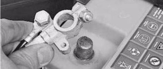
Checking the switch.
You can most likely check the switch using the arrow of a voltmeter if it is installed on the instrument panel or connect a voltmeter to the supply wires of the ignition system. When the ignition is turned on, the voltmeter begins to show the voltage of the on-board network, and after a while, about 10 - 15 seconds, the needle should deviate even further indicating an increase in voltage. This occurs due to the switch disconnecting the ignition coil, which occurs if the crankshaft does not start rotating.
If there is no voltage increase, then you need to check the presence of power at the ignition coil terminal of the switch. To do this, disconnect the connector from the switch, turn on the ignition, connect one end of the indicator lamp to the car body, and touch pin 4 on the connector with the other. If the control lamp is on, then power is supplied to the switch. Touch the test lamp to pin 1 of the switch connector. If the control lamp is on, then there is power to the ignition coil and the primary winding of the coil is intact. If the warning light does not light, check the power at the ignition coil terminals. The presence of power at terminal “B” and absence at the second terminal indicates a break in the primary winding of the ignition coil, and the presence of power at both terminals indicates a break in the wire from the coil to the switch.
If there is no power at pin 4 of the connector and terminal “B” of the ignition coil, it is necessary to check the contact group of the ignition switch. To do this, check for power on the blue wire with a black stripe. If there is power on it, eliminate the break in the wires or poor contact in the connections in the circuit from the ignition switch to the ignition coil and the switch.
If there is power at pins 4 and 1 of the switch connector, then it is worth checking for the presence of a minus on the same connector. To do this, connect one end of the test lamp to pin 4, and touch the other end to pin 2 of the connector. If the test lamp does not light up, then clean the contact in the connection of the negative wire with the car body. This completes the test of the switch. If the wire is in good condition and the connection is good, in 90% of cases the switch is faulty. In my practice, the statistics are 100%. If there is a voltage increase, then the switch is working.
In this case, it is better to continue checking with the serviceability of the timing belt. This is best done by removing the distributor cover and cranking the engine with the starter. If the runner does not rotate, then the belt breaks. If the belt is intact, then there is a malfunction in the ignition system of the VAZ 2109.
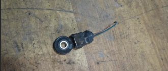
Checking the Hall sensor.
We check the serviceability of the Hall sensor and connecting wires if there is a malfunction in the ignition system of the VAZ 2109. To check the Hall sensor without disconnecting the connector from the switch, you must connect a voltmeter to the green wire, pin 6, and the white wire with a black stripe, pin 3. IMPORTANT: the internal resistance of the voltmeter must be not less than 100 kOhm. After this, we begin to slowly turn the distributor axis using the camshaft bolt or by hand with the distributor removed. In this case, the minimum voltmeter reading with a working sensor should not exceed 0.5V, and the maximum value should not be lower than 9V. if the readings are within the normal range, then the sensor and connecting wires are in good condition. If the readings are different, check the voltage by connecting a voltmeter directly to the connector on the distributor. If the readings also do not correspond to the norm, then the sensor is faulty, otherwise the connecting wires are faulty.
If the switch and Hall sensor are working properly, you need to check the integrity of the central wire. The faulty wire should be replaced. If all equipment is in good working order, the ignition coil should be replaced. There may be a break in the secondary winding, which can be checked with an ohmmeter, or the insulator is broken and there is a current leak to ground.
Advantages of contactless systems
For an ignorant car enthusiast, the main argument in favor of BSZ is the fact that at the moment not a single manufacturer produces cars with a contact-cam spark generation system. Foreign brands abandoned it in the distant 80s of the last century, and in the Russian Federation mechanical ignition lasted until the 90s. The reasons for the refusal are quite clear:
- sparks constantly flashed across the contacts, causing them to burn and require frequent cleaning;
- the contact group wore out quite quickly, on average it was enough for 15-20 thousand kilometers, after which the element had to be replaced;
- the wear of the bearing on which the contacts were located made itself felt, which caused unstable operation of the power unit;
- the springs of the balance weights were stretched.
All of the listed malfunctions appeared one by one, haunting the owner of the “classic” Zhiguli. Due to an imperfect design, the spark power of the spark plugs was constantly decreasing, engine performance was deteriorating, and fuel consumption was increasing. New BSZ systems are free of such disadvantages; they are characterized by durability and stable sparking. The spark power also increased, since the output pulse voltage increased from 16-18 kV to 24 kV, which contributes to better ignition of the fuel.
At first, the weak point of domestic contactless systems was considered to be the switch, which quickly failed and could not be repaired. But later it was improved and the reliability of the BSZ increased.
What is an ignition system switch
To put it simply, the ignition system switch means a simple electrical circuit that stands in the way of the electric charge between the ignition coil and the spark plug, which ignites the mixture of air and gasoline in the boilers. What is the meaning, purpose and operating principle of this ignition system device? In answering this question, it is worth understanding that there are two types of interrupting devices:
- Mechanical interrupt switches. Almost all cars of the Soviet Union were equipped with such electrical components until 1988. At that time these were practical, but extremely unreliable contact switches. The principle of their operation was based on the laws of self-induction, and was driven by a mechanical interrupter. The latter opened the primary low-voltage circuit, as a result of which an electromagnetic pulse arose in the secondary circuits of the transformer, which was converted into an electric spark and transmitted to the spark plug. In order to protect the contacts of the ignition system switch, a capacitor was included in the circuit.
- Non-contact switches, or as they are also called, transistor switches. Fundamentally, their work scheme is similar to their predecessors, but the mechanism for performing the work itself is different. So, unlike contact switches, contactless switches interrupt the current in electrical circuits using an input transistor, which serves as a gateway for the flow of electricity. The latest car models have switches that are fully electronically controlled.
At the same time, the latter clearly outperform the former, and with a big advantage.
Switch and ignition coil
So, for example, when using a transistor switch for a contactless ignition system:
- the current that passes through the breaker contacts decreases, as a result of which they stop burning and sticking;
- further, the duration of the spark supply increases, which automatically guarantees better ignition and more efficient burnout of combustible mixtures;
- if for some reason the transistor fails, you can always switch the wires to the standard position and the car will continue to work.
Purpose and types of switches
The VAZ 2107 electronic non-contact ignition switch is designed to interrupt the current supply in the primary purpose “bobbin” circuit based on pulses from the sensor, which is responsible for distributing the current supply in the ignition system.
Ignition system VAZ 2107
Such switches for the VAZ 2107 come from different manufacturers: Remix, HIM-52, or BAT. The switch circuit has the ability to automatically interrupt the current supply through the ignition system bobbin when the power plant is turned off, but the system is turned on.
This electronic device transforms the directive signals of the non-contact type sensor into electrical impulses arriving at the primary winding of the bobbin. If the VAZ switch of the “seventh” model malfunctions, this defect cannot be eliminated without electronic testing equipment.
How to recognize switch faults
Ignition problems are always accompanied by characteristic symptoms that every car owner should be aware of. One of these faults is related to the switch.
Here are just the most common signs indicating problems with the operation of the VAZ 2108 switch.
- The engine cannot be started.
- The starter actively turns the engine flywheel, but there is no spark.
- The engine can be started, it idles, it can be raised to medium speeds, but it is impossible to increase the speed to maximum.
- The motor is not running at full power.
- At idle, the engine runs fine, but begins to stall when trying to start.
- The engine can be started, but it stalls after a short time.
- One of the cylinders refuses to work at a certain speed (troit).
- The engine stalls when hot and continues to run normally when it cools down.
- The battery discharge lamp is on.
- The tachometer shows sharp jumps in engine speed.
These are just the most common, but not the only features of a faulty switch. There are also a number of indirect signs. Sometimes even experienced technicians cannot immediately identify the symptoms of malfunction of this unit of the VAZ 2108 ignition system.
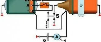
Testing the switch
Here we will look at how to check the switch on a VAZ 2106 for the purpose of its further use. The necessary check of the switch is carried out in case of suspected defects in this electronic device using instruments - an oscilloscope and a pulse signal generator of a rectangular configuration.
The resistance value at the output of the generator device should be 0.1 - 0.5 KOhm. It is better to use a two-channel oscilloscope because one channel is used to measure generator characteristics, and II - for switching signals.
Rectangular pulses, similar to the signals of an electronic device - the ignition distributor, are transmitted to the switch contacts. In this case, the frequency of such signals should be within the limits of 3 - 233 Hz, and the duty cycle factor (the ratio of the period to the signal duration) should be 3.
The extremely high voltage Umax should be 10V, and the extremely low voltage Umin should be 0.4V. Such a VAZ 2106 switch, when operating correctly, should display the geometry of pulse values corresponding to the oscilloscope reading.
Control parameters: For product 3620.3734 - voltage corresponds to 13.5 + 0.01 V and current 7.5 - 8.5 A, and for N1M-52 - the proportion should be 13.5 + 0.2 V to indicators 8 - 9 A with an accumulation time interval of 5.5 - 7.5 ms.
For the VAZ 2106 VAT 10.2 ignition switch, the voltage to current ratio is suitable in the form of a proportion of 13.5 to 7.5 - 8.5 A with an accumulation time interval of 5.5 - 7.5 ms.
If the shape of the product’s pulse signals is incorrect, interruptions in the formation of format pulses may occur, or it may be time-shifted. This will lead to overheating of the motor, which will not allow it to operate at full dynamics. Now car enthusiasts will know how to check the switch on the “six”.
The serviceability check can be viewed using the following scheme:
Scheme of operation of BZS VAZ 2107
The general connection diagram for the VAZ 2107 switch is an integral part of the general electrical equipment diagram for the “six”.
Important! To avoid failure of the VAZ 2107 ignition system switch, when the ignition is on, do not disconnect it from the circuit and do not remove the battery terminals even when the power plant is running. It is also necessary to control the reliability of the contact of the “ground” of the device to the body of the car in order to avoid creating preconditions for the failure of the switching device.
Signs of a faulty switch: how to check the switch yourself.
Purpose and design features of the switch.
A switch is one of the elements of a car's electrical equipment. His task
– ensuring normal operation of the contactless ignition system. The assembly is fastened in the engine compartment.
The device is different
reliability, ability to withstand severe vibrations and shock loads. This is very important, because the switch housing contains sensitive electronics.
At the heart of the VAZ switch
– standard L 497 microcircuit, which controls an “NPN” type transistor.
>Scheme feature
– possibility of programming by the user and setting the required delay coefficient. Starting a cold engine directly depends on the correctness of this indicator.
Thanks to precise settings
, you can speed up the crankshaft rotation speed (while eliminating failures in operation) and guarantee high-quality traction of the power unit.
The main parameters of the switch device include:
Voltage range – from 6 to 16 Volts; operating voltage level – 13.5 Volts; ensuring an uninterrupted spark when the crankshaft rotates in the range from 20 to 7000 rpm; switching current – from 7.5 to 8.5 A.
Signs of a faulty switch.
One of the main symptoms of a faulty switch is loss of spark.
. The engine starts hard and stalls from time to time, causing interruptions in operation.
But don't rush to replace it
- it is important to verify the reason, because
loss of spark can occur for a number of reasons
- failure of the Hall sensor, rupture of the timing belt, malfunction of the ignition coil, poor contact in the distributor cap, problems in the wiring, and so on.
If diagnostics of other nodes does not produce results
, then we can move on to our “hero”. But how to check the switch, since the device has a very complex design?
How to check the switch yourself.
Most car enthusiasts don’t bother with diagnostics and simply install a new unit. This method has its advantages.
Firstly
, there is no need to waste time checking - just install a new part.
Selecting an electronic ignition kit
Since the “sevens” were equipped with three types of engines (volume 1.3, 1.5 and 1.6 liters), the BSZ kits for them differ in the design of the distributor. The engine has 1.3 liters. (model VAZ 21073) there is a distributor with a shortened shaft, and in 1.5 and 1.6 liter engines. (VAZ 21071 and 2107 respectively) this shaft is equally long. The electronic ignition kit contains the following:
- distributor with catalog number 38.3706–01 for a 1.3 liter power unit. or 38.37061 - for 1.5 and 1.6 liter engines;
- high voltage coil marked 27.3705;
- electronic control unit, marking - 36.3734 or 3620.3734;
- connecting wires.
When buying a contactless kit for the “classic” Zhiguli, do not confuse it with products intended for the Niva VAZ 2121; the distributors are very similar in appearance. But the “Nivov” part differs in technical characteristics and is marked as follows: 3810.3706, 38.3706–10 or 038.3706–10. It is strictly not recommended to put it on “seven”.
Of the manufacturers selling their ignition kits in the Russian Federation, the most popular among motorists are spare parts from the SOATE company from Stary Oskol. It is worth noting that the new spark plugs of the A-17DVR brand, installed on classic VAZs with electronics, are not included in the delivery package; they will have to be purchased separately. To experience the full results of the replacement, it is also recommended to install new high-voltage wires if you have not replaced them in the recent past.
Kit for installing contactless ignition for VAZ 2107
Preparing to replace the BSZ
The work of removing the old ignition and installing a new one does not require any special tools, devices or devices.
Contactless ignition VAZ 2107 set
An inspection ditch is not needed, and the entire operation can be carried out outdoors in good daylight. It is enough to have the following tools:
- a 13 mm open-end wrench for unscrewing the distributor fastening nut;
- using 10 and 8 mm wrenches, remove the coil;
- flat and Phillips screwdriver;
- pliers;
- electric or hand drill with a drill to match the diameters of the switch mounting screws.
To make the work easier, rent or from a friend a socket wrench with a long handle, which fits onto the ratchet nut and is used to rotate the crankshaft manually.
It is much more convenient to turn the crankshaft with a wrench.
First, perform several stages of preliminary disassembly:
- Open the hood and disconnect the negative battery terminal.
- Remove the high-voltage wires from the spark plugs and distributor cap.
- Unscrew the spark plugs.
- Place a screwdriver into the spark plug hole of cylinder 1 and turn the crankshaft until the piston reaches TDC. In this case, the mark on the shaft pulley will be opposite the longest mark marked on the cylinder block.
- Having matched the marks and prepared new parts, you can proceed to the main stage of work.
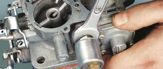
Replacing the switch on a contactless ignition system
An unscheduled replacement of the switch on the “seven” is carried out when it is impossible to operate the device due to a breakdown. Carrying out work of this kind is very simple; only initial knowledge in plumbing and electrical engineering and the availability of the necessary tools (a set of heads with a wrench and a ratchet) and a replaceable device are required.
This replacement of the VAZ 2106 ignition switch occurs in the following order:
- We disconnect the wiring from the “six” switch, which connects it to the breaker - distributor with a plug:
- We unscrew 2 body fasteners of the VAZ 2106 switch at different edges of the gadget; for this it is better to use a set of sockets with a ratchet and a wrench-extension:
- We dismantle the ignition switch to check it, and if necessary, replace it;
- Installation of this gadget follows the reverse principle.
Connection diagram for electronic ignition elements of VAZ 2107
How to set contactless ignition on a VAZ 2107
For the work you will need a 12-volt indicator light, a 13-volt wrench and a crankshaft wrench:
- You need to set the ignition with the engine not running, with the negative terminal of the battery disconnected.
- Set the piston of the first cylinder of the internal combustion engine to the ignition position. To do this, you will need to unscrew the spark plug from it. Plug the spark plug hole with your finger and at the same time turn the crankshaft clockwise with a wrench.
- When the compression stroke occurs, the air under pressure will begin to push the finger out strongly - this is what is needed.
- Now it is important to clearly align the mark on the pulley with the second one, which you look for on the timing cover. The mark in the middle means that the ignition advance is set to 5 degrees.
- It happens that some people cannot find their marks. But in fact, there are always marks. Just scrub the surfaces well with a metal brush and turn up the light.
- After setting the marks, you can remove the key. Wrap the removed spark plug back and connect the armor wire.
- The next stage of work will be to determine the ignition timing:
- Before you begin, connect the negative terminal of the battery.
- Using a 13mm wrench, you need to slightly loosen the ignition distributor mounting nut.
- Here you will need a prepared test light with two wires. We connect one terminal to ground, the second to the low-voltage ignition coil.
- Turn on the ignition by turning the key to position “I”.
- You need to carefully turn the ignition distributor housing clockwise until the warning light goes out.
- After this, you need to smoothly turn the distributor rotor counterclockwise until the contact is open and the light comes on again.
- Now you need to tighten the mount and check the behavior of the car while driving.
BZS adjustment
Adjusting the ignition of the VAZ 2107 begins with the simplest operation of removing the distributor cover, then turning the crankshaft until the maximum distance between it and the distributor is reached.
Installation process of BZS VAZ 2107
After this, they begin to unscrew the screws that fix the contact group on the bearing plate and between the contacts, insert a probe to determine and select the optimal position for the group
Contact angle correction in closed state
Ideally, everything is determined by the force applied to move the probe, which should be minimal; having found an area that meets this requirement, the position of the group is fixed by tightening the screws. The size of the gap also matters; to determine it, the thickness of the feeler gauge should be 0.44 millimeters. It is the adjustment of the gap that provides the required value of the angle of closed contacts; its optimal value is 55±3°.
Installation of BZS VAZ 2107
If the parameters correspond to the norm, then you can proceed to the second stage, which consists in adjusting the advanced ignition angle. To begin with, let us determine that the distributor chopper in the type of engine under consideration needs to realize the opening moment simultaneously with the spark in the first cylinder. This provides for an advance of the top dead center of the piston stroke for the first cylinder by 0±1°.
Lead angle correction using a strobe light
There are several ways to adjust this indicator, on which the correct ignition adjustment of the VAZ 2106 as a whole largely depends. The most efficient way to cope with this task is to use a strobe light. The device must be connected to the vehicle electrical network, and the vacuum correction hose must be removed and plugged from the distributor. Following this, the engine is warmed up until it maintains idle speed, followed by loosening the bolt responsible for fixing the distributor housing.
The light emitted by the strobe is directed to the crankshaft pulley; rotating the distributor body will allow you to achieve a position that ensures that the visible position of the mark on the pulley is opposite the corresponding marks marked on the timing cover. In this position, the distributor body is fixed by tightening it with bolts. The presence of idle speed of the power unit during the adjustment process is of decisive importance. If the speed is higher, the centrifugal regulator will take part in the work, which will distort the adjustment results.
Common malfunctions after installing a BZS
| Cause of malfunction | Remedy |
| Engine won't start | |
| The switch does not receive voltage pulses from the contactless sensor: | Do the following: |
| – a break in the wires between the ignition distributor sensor and the switch | – check the wires and their connections; replace damaged wires |
| – contactless sensor is faulty | – check the sensor using an adapter connector and a voltmeter; faulty sensor replace |
| No current pulses are supplied to the primary winding of the ignition coil: | Do the following: |
| – a break in the wires connecting the switch to the switch or to the ignition coil | – check the wires and their connections; replace damaged wires |
| – switch is faulty | – check the switch with an oscilloscope; replace faulty switch |
| – the ignition switch does not work | – check and replace the faulty contact part of the ignition switch |
| High voltage is not supplied to the spark plugs: | Do the following: |
| – the tips of the high voltage wires are loose or oxidized; they are not seated tightly in the sockets; the wires are heavily soiled or their insulation is damaged | – check and restore connections, clean or replace wires |
| – wear or damage to the contact carbon, its hanging in the cover of the ignition sensor-distributor | – check and, if necessary, replace the contact angle |
| – current leakage through cracks or burnouts in the cover or rotor of the ignition distributor, through carbon deposits or moisture on the inner surface of the cover | – check, clean the cover from moisture and carbon deposits, replace the cover and rotor if they have cracks |
| – burnout of the resistor in the rotor of the ignition sensor-distributor | – replace the resistor |
| – the ignition coil is damaged | – replace the ignition coil |
| The spark plug electrodes are oily or the gap between them is not normal | Clean the spark plugs and adjust the gap between the electrodes |
| Spark plugs are damaged (cracked insulator) | Replace the spark plugs with new ones |
| The order of connecting high voltage wires to the terminals of the ignition sensor-distributor cover is violated | Connect the wires in firing order 1–3–4–2 |
| Incorrect ignition timing setting | Check and adjust ignition timing |
Diagram of the contactless ignition system for VAZ 2108, 2109, 21099 cars
VAZ 2108, 2109, 21099 cars and their modifications use a non-contact ignition system. There is no breaker (as in the contact system). The moment of sparking is controlled electronically. Below is its electrical diagram and a description of the main elements.
Elements of the ignition system for VAZ 2108, 2109, 21099 cars
- Accumulator battery.
Provides electrical current when starting the engine. "VAZ battery"
Generator.
Provides electric current when the car engine is running. In particular, it powers the ignition system.
- Fuse and relay mounting block.
Serves for switching low voltage wires, in particular the ignition system.
- Ignition coil.
Provides high voltage current to the ignition distributor. “Ignition coil wires for VAZ 2108, 2109, 21099”
Provides a pulse for sparking (opening the power circuit of the primary winding of the ignition coil) in one or another cylinder according to a signal from the Hall sensor.
Generates a control pulse (reducing voltage) for the switch, signaling the need for sparking in one or another engine cylinder.
- Ignition distributor (distributor) with vacuum and centrifugal ignition timing regulators.
Serves to generate a control pulse to the switch (Hall sensor), distribute high voltage pulses across the spark plugs (“slider”), correct the ignition timing in accordance with the engine operating mode (centrifugal and vacuum regulators).
- High-voltage wires (armored wires).
They serve to transmit high voltage current from the ignition coil to the distributor cover and then to the spark plugs.
- Egnition lock.
Serves to close the ignition system circuit. Through it, electric current flows into the ignition system.
- Ignition relay.
Serves to relieve the contacts of the ignition switch (lock) and supply voltage to the coil and switch.
- Spark plug.
Serve to generate a spark in the engine cylinders.
Notes and additions
— This scheme of a contactless ignition system is applicable on VAZ 2108, 2109, 21099 cars produced before 1998. On cars after 1998. it's similar. The difference is in the names of the mounting block pads (Ш1 - Х1, Ш8 - Х8).