ZMZ 406 is a brand of internal combustion engine (ICE). The engines were manufactured at the Zavolzhsky Motor Plant (ZMZ) throughout the 90s of the last century. The engine became the first injection 16-valve engine with an electronic control unit (ECU) in the history of Russian mechanical engineering. The ECU controls all work processes using data from various measuring instruments. One of them is the camshaft position sensor of the ZMZ 406 engine (DPRV). ZMZ 406 engines were massively installed on cars such as the Volga, Sobol, Gazelle and RAF, which are still found on Russian roads.
Gas 31105 with ZMZ 406 engine:
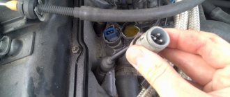
DPRV device
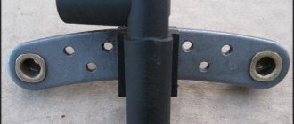
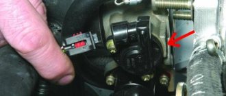
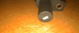
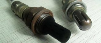
The device is often called a phase sensor. It is located on the right side of the engine cylinder head block when standing opposite the windshield. The device is secured with one bolt. DPRV is a plastic cylinder with an eye, in which there is a hole with a bronze ring.
DPRV ZMZ 406:
The lug divides the cylindrical body into two parts, one of which enters the opening of the cylinder head, and the second part is located outside with a cable and a connector at its end. Inside the housing there is a metal core in the winding, that is, a solenoid. Low-voltage power is supplied to the coil with two wires (+ and –), the third wire is connected to the core. The connector has a receiving chip with a cable connected to the ECU.
DPRV location:
Diagnostics of the ignition control system and engine of the Gazelle vehicle
Gazelle vehicles are the most popular and affordable truck in Russia, designed for transporting small loads. Since the number of such cars is becoming larger and larger, we should consider some of the nuances of various Gazelle systems, for example, the microprocessor ignition system, which is installed on the 406 modification. In this case, we will look at diagnosing a car whose owner complains of jerking, popping and loss of power.
The power system, engine and ignition will be checked. The carburetor was checked using a gas analyzer, but no problems were found in the operation of the first and second chambers, cut-off, idle speed, or idle enrichment. Next is the engine. The compression check did not reveal any violations, the readings of 9.6 kg/cm2 for the 406 engine coincided with the norm, however, a small deviation of 10% was detected during the re-check, so the valve timing was subjected to the next check. It turned out that the pops and jerks were a result of the upper chain jumping two teeth.
%rtb-4%
Gas distribution system
In the 406th modification, the engine looks like this: four valves are installed on each of the two exhaust and two intake cylinders, the right camshaft (front view) drives the exhaust, and the left camshaft drives the intake. Hydraulic valve drive clearance compensators from the camshaft cams eliminate the need for maintenance and adjustment. The camshafts are driven from the crankshaft by two bushing chains.
View of the correct assembly at TDC of the compression stroke with the piston position of the first cylinder of the camshaft drive:
1. The protrusion on the chain cover (M1) must coincide with the mark on the crankshaft sprocket (2), the horizontal marks (9) on the camshaft sprockets (10, 12) must coincide with the upper plane of the cylinder head.
2. The alignment mark (M2) on the cylinder block must correspond to the mark on the intermediate shaft sprocket.
The center of the twentieth tooth of the synchronization disk (3) must be located, at this position of the shafts, strictly opposite the center of the crankshaft position sensor core (4). The synchronization disk (1) is a gear on which there are 58 cavities located at a distance of 6 degrees from each other, two of which are missing for synchronization. The two missing cavities are the starting point for the tooth numbers (15), and the numbering proceeds in a reverse clockwise direction. However, adjusting the gas distribution system did not lead to the return of the engine's former power.
Now let's get down to diagnosing the ignition system. Control of the forced idle economizer valve in the sixteen-valve ZMZ-4063 carburetor engine and ignition is provided by the MIKAS 5.4 microprocessor system.
This system, which allows, depending on operating conditions and engine operation, to implement the most optimal SOP, it consists of wires with connectors, a control unit, a set of actuators and sensors.
High specific engine readings without fear of over-ignition and detonation are ensured through effective identification of the detonation combustion control unit of each cylinder and the knock sensor. If the sensors are damaged, the unit instantly implements emergency control mode. The crankshaft position sensor is an exception, since the engine cannot function without it.
Electronic control unit (ECU) Mikas 5.4
A DBP is installed on the engine panel of the vehicle - an absolute air pressure sensor on the intake manifold (Bosch model 0261230004), and is connected to the throttle body in the engine intake manifold. The amount of air that enters the engine cylinders is calculated by the control unit based on the measured value. This sensor looks like an electronic remote integrated device with a working chamber made of silicon and special powder, which has an exemplary pressure inside.
The conductivity of sensitive semiconductor elements located inside the working chamber varies directly depending on its mechanical location. The sensor is powered by a stabilized voltage of 5 V, and the output voltage is 0.4...4.65 V and linearly depends on the measured pressure, ranging from 0.2 to 1.05 atmospheres and is connected using a three-pin plug to the wiring harness. A change in the balance of the strain gauge bridge is caused by a displacement of the membrane (i.e., the working chamber), since the resistors are connected in a bridge circuit.
An electronic signal processing circuit, located on the same board as the sensing element, is connected to these resistors.
Absolute pressure sensor (MAP)
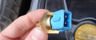
To determine the engine temperature, the car is equipped with a DTohl (coolant temperature sensor) models 19.328 or 40.5226, manufactured in Russia. The unit controls the forced-idle economizer valve and also adjusts the ECO valve in accordance with the measured temperature value. The control system consists of an ignition coil, a forced-idle economizer solenoid valve and a knock sensor. DTohl, installed on the outer shell of the cooling system thermostat, is connected to the harness using a two-pin connector.
Coolant temperature sensor (DTohl)
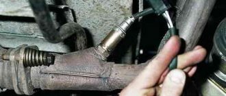
Opposite the crown of the crankshaft pulley toothed disk, in the boss of the gas distribution mechanism chain cover, an induction-type crankshaft position sensor (DPKV) model 23.3847 made in Russia, or model 0261210113 from the German company Bosch, is installed, which is connected by a flexible cable to a three-pin electrical plug.
This sensor has the form of a coil with a magnetic core, with a winding resistance of 880 to 900 Ohms. To ensure optimal operation of the control system, a gap of 0.5 to 1 millimeter is required between the teeth of the disk and the sensor.
In order to avoid damage to the sensor cable by rotating parts of the generator or engine, it must be secured as securely as possible, since a malfunction of the DPKV leads to the engine stopping.
%rtb-4%
Work principles
Using the signal from the crankshaft position sensor, the control unit calculates the rotation speed, and the amount of cyclic air filling of each of the four engine cylinders is determined by measuring the absolute pressure. The ignition timing angle, which depends on the cyclic filling and rotation speed, and corresponding to the engine operating frequency, is stored in the unit’s memory device.
How does DPRV work?
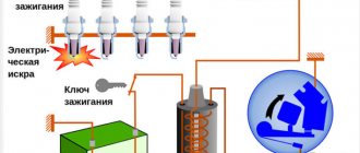
The ZMZ 406 phase sensor is the same Hall sensor. The device received its name from the American scientist who received a patent for it back in 1879. The operation of the device was based on the principle of distributing opposite charges along the edges of a magnetic conductor plate when entering a magnetic field. With the slightest change in the intensity of the magnetic flux, the potential difference on the metal plate immediately changed.
Using this effect and rare earth elements such as germanium, indium and silicon, only in the second half of the last century it was possible to create microcontrollers that measure changes in current characteristics. Such devices include DPRV. Its tip is located in close proximity to the camshaft head with a projection. As soon as - during the rotation of the shaft - a protrusion appears opposite the tip, the core, under the influence of electromagnetic induction, changes its potential, which the ECU notifies. The processor, analyzing the incoming signal from the device, adjusts the operation of all internal combustion engine systems.
How to check DPRV
Checking the sensor will become necessary after the “Check Engine” sign lights up on the instrument panel and the ECU writes the camshaft sensor error code to its memory. You can identify a malfunction of the DPRV at a diagnostic center by connecting the connector on the car to the appropriate equipment. This type of operation is not cheap. There is a fairly simple way to check the sensor yourself using a multimeter. Proceed as follows:
- Raise the hood cover. Locate the sensor at the end of the cylinder head near the windshield.
- Remove the contact cover of the ECU cable from the meter connector.
- One multimeter probe (+) is connected to the middle contact of the DPRV, and the second wire is connected with the contact to ground (0) of the machine.
- The multimeter is switched to voltmeter mode.
- Turn on the ignition. A working device will produce a voltage of about 10.8 V, which is 91% of the 12 V supply. Otherwise, the sensor must be replaced.
Checking the DPRV with a multimeter:
Description of sensors of the ZMZ engine control system
The Gazelle and Volga cars are equipped with the ZMZ engine produced by the Zavolzhsky Motor Plant. Power units of this type are equipped with many different sensors and controllers, the purpose of which every car owner should know. You can find out what MAF, DTOZH, DPKV and other regulators on the ZMZ 406 are from this material.
The thread or film mass air flow sensor on the ZMZ 402, ZMZ 405, ZMZ 409 engines is fixed on one side to the throttle, and on the other to the air filter element. It is secured using rubber hoses and clamps. The purpose of the element is to determine the mass of the air flow that is sucked in by the motor. The device is connected to the ECU wire block using a special contact socket. Depending on the model of the power unit, a special potentiometer may be located on the component, which is necessary to adjust the CO content.
Oil pressure
The ZMZ oil pressure controller is a device designed to convert mechanical force into impulse. This pulse can have different voltages. After the control unit deciphers the signal, it will be able to find out the exact fluid pressure in the system. As you know, consumables are supplied to the friction elements of internal combustion engines using different methods.
Installation location of the engine fluid pressure regulator
If the pressure level decreases, this may indicate a lack of consumables in the system. Much less often this indicates that the oil pump has failed. In this case, the friction between the elements and components of the power unit will increase, and accordingly, this will lead to increased wear of the components. And sometimes this can even cause them to jam. If the oil pressure sensor fails, it must be replaced as quickly as possible.
Air temperatures
The temperature controller is installed on the motor receiver; its connection must be sealed. This device provides control of the thermal state of the unit. In some cases, the symptoms of a malfunction of a given element can be eliminated by ensuring a better seal of the connection.
The design of this controller is a zener diode (semiconductor). It is powered by 5 volts, so the device is connected to the control unit (the author of the video is Budni Gazelista).
DTOZH
The coolant temperature sensor or coolant temperature sensor is mounted on the thermostat housing. The device must be connected as tightly as possible, so a sealant is used for a better connection. The purpose of the element is to control the thermal state of the power unit.
The engine cooling temperature regulator is a semiconductor zener diode that has a reverse switching function and is powered by the computer. If the device fails, most likely the instrument panel will show the wrong engine temperature.
TPDZ
The throttle position sensor is mounted directly on the throttle, on top, this element is fixed to the unit using two special bolts. Since the throttle axis itself is equipped with a so-called flat, when installing the controller, it will need to be aligned with the slot on the element axis clamp. To make the connection of the components as tight as possible, a rubberized seal is additionally used (the author of the video about replacing the device is the channel Igor48355).
As for the purpose of the TPS, the ZMZ throttle valve controller is designed to detect the rate and degree of throttle opening. The DPDC itself is an ordinary potentiometer with a current collector that moves along a designated radius of the so-called current-carrying sector. This radius ranges from 0 to 100 degrees.
The device's output impedance level can vary depending on how far the throttle is open. As for the power supply, the regulator is powered using a cable connected to the control unit. The controller itself is directly connected to the wiring block using a special three-pin connector with a lock. If the regulator fails, you simply need to disconnect the mount and disconnect the wiring, and then replace it.
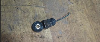
Detonation
The request returned an empty result.
Detonation is an unauthorized ignition of the air-fuel mixture in the cylinders of the power unit. If the engine operates in this mode for a long time, this can lead to high vibrations, as well as high loads on the internal combustion engine components. Ultimately, this contributes to more accelerated wear of engine parts, in particular, we are talking about the pistons of the unit, cylinder head gasket, rings, etc. The engine knock sensor is mounted on the right side of the BC; it itself is a piezoelectric regulator.
The main components of the device are a quartz piezo component, as well as an inertial mass. When an internal combustion engine is running, many of its components vibrate. Due to detonation, higher vibrations are formed in the system, as a result of which the voltage amplitudes of electrical pulses in the power unit sharply increase. The impulses themselves are transmitted to the ECU.
In accordance with the signals received from the controller, the ECU adjusts the ignition timing until the detonation stops. If the element itself or one of the electrical circuits breaks down, the ECU will notify the car owner about this via a light indicator on the dashboard.
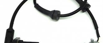
Crankshaft
The crankshaft sensor or DPKV is an inductive type device; it is mounted in the front of the engine, on the right side, at the bottom. DPKV works together with a synchronization shaft equipped with 60 teeth, 2 of which are pre-removed. These two teeth are missing for a reason - their position corresponds to the top dead center of 1 or 4 cylinders of the internal combustion engine. The purpose of the DPKV is to synchronize the control phases of the electrical mechanisms of the system with the timing phases. The regulator marks each crankshaft revolution, thanks to which the computer calculates the injection phases, as well as the ignition timing.
The optimal backlash between the end part of the controller, as well as the tooth of the synchronization disk, is about 0.5-1.2 mm. The element itself is powered by the control unit and is connected to it by wire using a three-pin connector.
Sorry, there are no surveys available at this time.
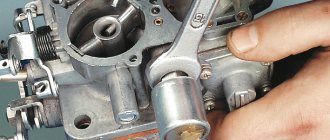
Replacing the DPRV
Replacing a burnt-out sensor with a new device is not difficult. They do it like this:
- Remove the negative terminal from the battery and put the car on the handbrake.
- Using an open-end wrench “10”, unscrew the sensor mounting bolt.
- Remove the chip from the DPRV connector.
- The sensor with cable and connector is removed from under the hood. A new device is installed in its place.
- Tighten the fastening bolt.
When purchasing a new camshaft position sensor, you must definitely pay attention to whether the device belongs to the ZMZ 406 engine, because controllers from other car brands will not be suitable for mounting. Do not buy DPRV from unknown manufacturers. All the benefits of a purchase can turn into an unpleasant car stop far from home.
Lessons 406
The electrical equipment of a car with a ZMZ-4062.10 engine can be divided into two groups.
First group
These are devices familiar to us from the old “402” engine: starter, generator, battery, spark plugs, ignition coil, coolant temperature sensors, oil pressure, relays and others. They may be slightly different in design and parameters, but their operating principle is the same and is well known. Even checking spark plugs in a new engine is carried out in exactly the same way as in the old one.
Case one
Winter, frosty morning. You are in a hurry to get to work, confidently get behind the wheel of your Volga, turn on the ignition, and see the warning light come on and go out. Everything is fine. You turn on the starter, but the engine does not start. How so? Yesterday I left the car in working order, the light does not “scream” about a malfunction, and the engine is silent.
Remember.
The self-diagnosis mode does not apply to the high-voltage part of the vehicle's electrical system. Most likely, the engine’s spark plugs are “flooded,” and the control light doesn’t care. But don’t rush to unscrew the spark plugs, clean them and heat them. The “4062.10” engine has a cylinder purging mode, but the manufacturers forgot to inform car owners about this.
The GAZ instructions say that when starting the engine, you should not press the gas pedal. Why not? Yes, because if you press it more than halfway, the cylinder purging mode is activated! Air enters the cylinders, but fuel does not. When you blow the cylinders for 5-10 seconds, the engine will start when you release the gas pedal.
Case two
Summer. In the evening, returning home, you were caught in a warm mushroom rain. We parked the car in the garage and noticed a puddle of water on the front passenger's carpet. Just think! And the old Volga was leaking into the edge of the front window. It's like a birthmark...
And in the morning your brand new Volga starts and stalls, starts and stalls... How do you know that the most important electronic “brain” of your car is located under the glove box and it got under the shower.
Remember.
Any electronics does not like moisture or dampness. She seems to be going crazy, giving inconsistent commands.
We carried out measurements on such a “wet” control unit; it transmitted signals to the engine based on an ambient temperature of -12°C, when it was +20°C outside. So he went deaf from such a weather forecast!
Case three
You have decided to wash your car. We drove it out onto the lawn and washed it without opening the hood. They started it up and found that the engine was “troubling.” How can that be, you didn’t wash it!
Everything is very simple. The Volga often has leaks where the rear part of the hood fits on the rubber seal, and when washing, water gets directly onto the electromagnetic injector of the fourth cylinder.
In all cases of water getting on contacts, connections, devices, it is necessary to dry, ventilate, use modern moisture displacers and, of course, thoroughly eliminate all possible moisture ingress into the electrical system. It is also necessary to skillfully arrange a general wash of the engine and engine compartment. It is better to consult a service station.
And the last thing that owners of the “406” need to know. This engine is demanding on the quality of spark plugs. Avoid buying so-called “imported” ones in markets, in gateways, no matter how tempting the price and packaging may be. If you don’t have the money to buy imported spark plugs from real dealers, it’s better to buy domestic ones. And before installing it on the engine, check everything for operation under pressure at a service station.
Integrated Control System Diagnostic Trouble Codes
| 12 | The initial code for displaying diagnostic information (always the first one). |
| 13 | Low signal level from the air flow sensor |
| 14 | High signal level from the air flow sensor |
| 15 | Low signal level from the absolute pressure sensor |
| 16 | High signal level from the absolute pressure sensor |
| 17 | Low signal level from air temperature sensor |
| 18 | High signal level from the air temperature sensor |
| 21 | Low signal level from coolant temperature sensor |
| 22 | High signal level from the coolant temperature sensor |
| 23 | Low signal level from throttle position sensor |
| 24 | High signal level from the throttle position sensor |
| 25 | Low voltage level in the vehicle's on-board network |
| 26 | High voltage level in the vehicle's on-board network |
| 31 | Low level from the first CO corrector |
| 32 | High level from the first CO corrector |
| 33 | Low signal level from the second CO corrector |
| 34 | High signal level from the second CO corrector |
| 35 | Low signal level from the first LAMDA probe |
| 36 | High signal level from the first LAMDA probe |
| 37 | Low signal level from the second LAMDA probe |
| 38 | High signal level from the second LAMDA probe |
| 41 | Malfunction in the first knock sensor circuit |
| 43 | Recirculation valve feedback signal low |
| 44 | Recirculation valve feedback high |
| 45 | Canister valve feedback signal low |
| 46 | Canister valve feedback signal high |
| 51 | Malfunction of 1 control unit (CU) |
| 52 | Malfunction 2 CU |
| 53 | Synchronization sensor malfunction. |
| 54 | Phase sensor fault |
| 55 | Vehicle speed sensor malfunction |
| 61 | Malfunction 3 CU |
| 62 | Faulty RAM memory |
| 63 | Malfunction of the permanent memory of the control unit |
| 64 | Malfunction when reading the non-volatile memory of the control unit |
| 65 | Malfunction when writing to the non-volatile memory of the control unit |
| 71 | Low engine speed when idling |
| 72 | High engine speed when running |
| 73 | Lean mixture when regulated by the first LAMDA probe |
| 74 | Rich mixture when regulated by the first LAMDA probe |
| 75 | Lean mixture when regulated by the second LAMDA probe |
| 76 | Rich mixture when regulated by the first LAMDA probe |
| 81 | Maximum displacement of the OZ when regulating by detonation in the first cylinder |
| 82 | Maximum displacement of the OZ when regulating by detonation in the second cylinder |
| 83 | Maximum displacement of the OZ when regulating by detonation in the third cylinder |
| 84 | Maximum displacement of the OZ when adjusting for detonation in the fourth cylinder |
| 91 | Malfunction in the ignition control circuit of the 1st cylinder |
| 92 | Malfunction in the ignition control circuit of the 2nd cylinder |
| 93 | Malfunction in the ignition control circuit of the 3rd cylinder |
| 94 | Malfunction in the ignition control circuit of the 4th cylinder |
| 99 | High voltage driver malfunction |
| 131 | Malfunction of the injector of the 1st cylinder (short circuit) |
| 132 | Malfunction of the injector of the 1st cylinder (break) |
| 133 | Malfunction of the injector of the 1st cylinder (short circuit to ground) |
| 134 | Malfunction of the injector of the 2nd cylinder (short circuit) |
| 135 | Malfunction of the injector of the 2nd cylinder (break) |
| 136 | Faulty injector of the 2nd cylinder (short circuit to ground) |
| 137 | Malfunction of the injector of the 3rd cylinder (short circuit) |
| 138 | Malfunction of the injector of the 3rd cylinder (break) |
| 139 | Malfunction of the injector of the 3rd cylinder (short circuit to ground) |
| 141 | Malfunction of the injector of the 4th cylinder (short circuit) |
| 142 | Malfunction of the injector of the 4th cylinder (break) |
| 143 | Faulty injector of the 4th cylinder (short circuit to ground) |
| 161 | Malfunction of winding 1 RDV (short circuit) |
| 162 | Malfunction of winding 1 RDV (break) |
| 163 | Faulty winding 1 RDV (short circuit to ground) |
| 164 | Malfunction of winding 2 RDV (short circuit) |
| 165 | Malfunction of winding 2 RDV (break) |
| 166 | Faulty winding 2 RDV (short circuit to ground) |
| 167 | Malfunction in the control circuit of the fuel pump relay (SC) |
| 168 | Malfunction in the fuel pump relay control circuit (open) |
| 169 | Malfunction in the control circuit of the fuel pump relay (short circuit to ground) |
| 171 | Recirculation valve circuit malfunction (short circuit) |
| 172 | Recirculation valve circuit malfunction (open) |
| 173 | Recirculation valve circuit malfunction (short to ground) |
| 174 | Malfunction in the canister valve circuit (short circuit) |
| 175 | Malfunction in the canister valve circuit (open) |
| 176 | Malfunction in the canister valve circuit (short circuit to ground) |
| 177 | Main relay control circuit malfunction (short circuit) |
| 178 | Main relay control circuit malfunction (open) |
| 189 | Main relay control circuit malfunction (short to ground) |
| 181 | Malfunction lamp circuit malfunction (short circuit) |
| 182 | Malfunction lamp circuit malfunction (open) |
| 183 | Malfunction lamp circuit malfunction (short to ground) |
| 184 | Malfunction in the tachometer circuit (short circuit) |
| 185 | Malfunction in the tachometer circuit (open) |