Sensor diagnostics
You can check the idle air valve yourself. Its faults can be divided into two parts: mechanical and electrical. There are several verification methods.
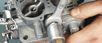
Visual inspection
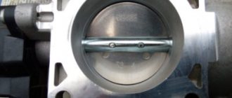
First you need to conduct a visual inspection. In this way, you can detect body defects, needle wear, and carbon deposits. If deposits form, you can clean them with carburetor cleaner. It is also recommended to clean the entire throttle body as it is in a similar condition.
Using diagnostic programs
The operation of the IAC can be checked using a diagnostic adapter and special programs. For example, you can use the simplest ELM327 adapter and the OpenDiagMobile program. In the program menu you need to select the desired position of the XX regulator and watch the operation of the valve. It is better to set it at least 20 steps more than the current position.
Wiring check
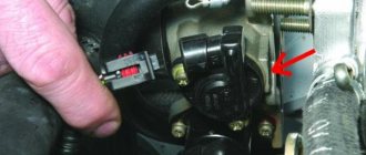
For this we need a multimeter. With the engine off, remove the connector from the sensor. We set the measurement limit on the measuring device to 0-20 V DC voltage. We measure the voltage at the connector. Normally it should be 12V.
Checking the regulator resistance
To do this, we will need to measure the resistance between terminals A, B, and C and D after disconnecting the sensor terminal. We move the multimeter to the position of measuring resistance at the limit of 0-200 Ohms (Ω).
The normal value is within 50-55 Ohms. The resistance between A and C, B and D must be infinity.
Checking with throttle assembly
There is another way to diagnose IAC. To do this, you will need to remove the throttle assembly from the studs along with the sensor.
By connecting the valve connector and turning the ignition on/off, you can observe the operation of the IAC live. See how the needle works, if it is rubbing somewhere, check the evenness of the stroke, hear suspicious sounds.
Idle adjustment
It is recommended to start adjusting the idle speed only when the previous adjustment step has already been completed. To configure this parameter you need to:
- Tighten the quality screw counterclockwise until it stops. This part is located in the hole in the carburetor sole.
- Screw the quality screw six turns to the right.
- Start the engine and remove all gasoline leaks.
- Find the quantity screw and use it to set the minimum speed for the engine. It is best if the mechanism operates at 900-1200 rpm.
- Slowly and carefully tighten the quality screw until the motor begins to operate in an unstable mode. After this, it is necessary to restore stable operation by tightening the screw in the opposite direction one to one and a half turns.
- By rotating the quantity control screw, set the idle speed to 850-900 rpm; if necessary, you can tighten the quality screw.
Adjustment of different types of carburetor is carried out according to the same scheme
Problems with setting the idle speed can arise due to a defective nozzle, a “third-party” leak of gasoline, for example, when the solenoid valve or plug is not tightly closed, or an incorrectly sized nozzle.
It is worth noting that this mechanism is not recommended for engines with a volume of more than one and a half liters, as this can lead to engine malfunction at high speeds. Also, to increase the power of the base carburetor, it is best to replace the original jets.
And one more important point - carburetor adjustments must be made only when the engine is warm.
Adjustment of many types of carburetors is carried out approximately according to the same principles. Depending on the manufacturer, a similar scheme may also be relevant for adjusting this mechanism on a scooter, and can also be used for a motorcycle. But if the vehicle is under warranty, it is not recommended to adjust the carburetor yourself. In this case, if it is necessary to exercise the right to warranty repairs at the official service center of the manufacturer, specialists may refuse to provide these services. This almost does not apply to domestic vehicles, but on most foreign cars the factory equipment must be maintained until the end of the warranty period, then the car owner can, if necessary, calmly contact the service center.
Thus, adjusting the carburetor of a VAZ 2105, 2106 and others is quite simple; for this it is not necessary to contact specialists; you can configure this mechanism yourself.
How to replace the idle speed sensor
Before starting work, remove the negative terminal from the battery. Disconnect the four-pin connector from the sensor to be replaced by first pressing the plastic latch (if available). Remove the pair of screws securing the regulator. Take a new device, lubricate the o-ring, spring and rod with engine oil: this will increase the life of the regulator.
Now you need to calibrate the newly installed product. To do this, put the negative battery terminal in place and turn on the ignition for 15 seconds without starting the engine. During this time, the control unit will calibrate automatically. Next, start the engine and check how the sensor functions on a running power unit. If the idle speed is higher than normal, then the procedure must be repeated (possibly more than once). With the idle speed control operating normally on a cold engine, the tachometer will show approximately 1000 rpm. After reaching operating temperature, they will drop to around 800 rpm. It is worth noting that discrepancies with these indicators may be caused by the use of low-quality fuel.
Reasons for high speed on the injector
On the injector, the reasons why the speed increases can be divided into:
- related to electronic malfunctions;
- associated with mechanical problems.
In the first case, the sensors or controllers are acting up. In case of malfunctions of this kind, it is best to seek the help of specialists.
Throttle valve
If the reason lies in the poor functioning of the throttle valve (in most cases, it becomes jammed), the following happens:
- the volume of air entering the cylinders increases disproportionately;
- The ECU will "demand" more fuel to balance the mixture.
As a result, the car will not only consume much more fuel than it should, but it may even fail due to constant “overload” at high idle speeds. Diagnostics of the damper and, depending on the diagnostic results, chemical cleaning or replacement will help resolve the problem.
Engine temperature sensor
This device is considered subject to frequent failures, since it is located in the epicenter of inevitable temperature changes. If it was noticed that with certain initial conditions everything is in order with the motor, but the sensor is “playing naughty”. To diagnose, you will have to delve into the wiring.
With the ignition on you need to:
- take data on the resistance from contact “A” to ground (the exact correct value is 10 Ohm);
- take data on the resistance from ground to terminal “B” (if less than 10 Ohms, you need to sound the alarm;
- also take data on the voltage at terminal “B” in relation to ground (the exact correct value is 5V).
There may be a problem with the sensor itself. To determine this, you need to take the above resistance readings with the engine cooled down and warmed up. When working properly, the readings should not differ.
Engine temperature sensor
Air flow sensor
The oil film that envelops this device during vehicle operation eventually leads to malfunctions of the element that measures and sends a signal to the computer about the amount of incoming air (hot-wire anemometer). As a result, the ECU does not have access to reliable information about the amount of air, and the speed begins to float. But first of all, it is worth inspecting the air filter. Perhaps it is simply clogged and air is not flowing freely.
Intake manifold
High speeds may be associated with air suction. There can be two types of faults in this unit:
- deformation of the intake manifold;
- breakdowns or burnout of the gasket.
If the second case is not so catastrophic, then the first will most likely lead to a call to the services of a car service, since grinding may be required. Problems will be detected, including when the engine warms up.
Other reasons
Other common reasons may be the following:
- jamming of the gas pedal, which is typical for both an injector engine and a carburetor engine;
- On the injector, the IAC (idle air control) and TPS (throttle position) sensors may fail: if there is a suspicion that it is they who are “sinning,” you will need to check the contacts;
- ECU failures, which are checked using special computer programs;
- the generator does not supply the required current rate, so the motor will begin to accelerate in pursuit of the required voltage;
- For cars with a turbocharger, high speeds at idle can be caused by its wear or depressurization of the rotor shaft gasket.
If you cannot confidently identify the cause of the increase in speed, it is more prudent to contact specialists (especially in the case of an injector).
Intake manifold with throttle valve
Sensor diagnostics and replacement procedure
The main symptoms of a malfunctioning idle speed sensor are as follows:
- unstable engine speed;
- increase or decrease in speed for no apparent reason on a warm engine;
- spontaneous engine stop;
- low engine speed when warming up;
- a sharp decrease in speed when power consumers are turned on.
If they are detected, it is necessary to begin the process of diagnosing the regulator.
This is done as follows:
- The car is placed on a flat surface.
- The 2 bolts securing the regulator are unscrewed, then it is pulled out. All operations must be carried out with the ignition turned off.
- Then you should visually inspect the rod for any contamination that would interfere with its free movement.
- If there are none, then you can turn on the ignition and connect the sensor to the connector - on a working regulator, the needle moves noticeably.
If you have a multimeter at hand, you can make a more accurate diagnosis. To do this, you first need to measure the voltage supplied to the sensor - for the VAZ 2114 idle speed regulator it should be about 20 Volts. If there is no voltage, it is necessary to check the contracts or the ECU unit, if the nominal value is exceeded or decreased - the condition of the electrical equipment of the car. Measuring the winding resistance on the sensor should show a value within 53 Ohms.
Replacing the regulator is quite simple:
- The connector is disconnected.
- The fastening bolts are unscrewed.
- The faulty sensor is removed and a new one is installed in its place.
- The bolts are tightened.
- The contact chip is installed.
Attention! All work must be carried out with the ignition turned off.
After installing the sensor, it must be calibrated. To do this, you need to turn on the ignition for 5–10 minutes, start the internal combustion engine and let it idle for about a minute, then turn it off. When you restart the engine, the sensor will calibrate itself.
It should be borne in mind that it makes no sense to restore the functionality of a faulty sensor - it can fail again at any time, and the cost of a new part, even for foreign cars, is low.
With the help of the Uremont.com service, you can diagnose and repair your car on your terms. Just create a request and choose the service station that suits you. Repairing with us is fast, profitable, and reliable.
Device diagnostics
Motorists are interested in how to check the idle air valve themselves and its current condition.
For many car enthusiasts, independently checking this valve, a component of the idle air system, is a completely doable task. There are several methods for diagnosing the condition of the regulator.
- Visual inspection. First a visual inspection is carried out. This allows you to determine the presence of defects on the body, signs of needle wear, and signs of carbon deposits on surfaces. If there are deposits, they can be removed using carburetor cleaner. Surely, if the IAC is dirty, the entire throttle assembly will be dirty. Therefore, it will not be superfluous to clean it too.
- Diagnostic software. Some car enthusiasts are switching to using special diagnostic programs. In addition to the software, an adapter is also required to connect to the system. Through the software menu, the position of the controller is selected and its operation is observed.
- Wiring condition. It would not be superfluous to carefully check the wiring connected to the IAC. Here you need to use a multimeter. The engine is turned off, the sensor connector is removed. On the multimeter, select the voltage test mode with a limit from 0 to 20 V. When working properly, the device should show about 12 V.
- Resistance. The resistance of this regulator is also checked. To do this, using the same multimeter, the resistance between the terminals is checked by disconnecting the sensor terminals. The multimeter is turned on in resistance mode, and the limits are set from 0 to 200 Ohms. The terminals are conventionally designated as A, B, C and D. When measuring resistance at A and C, as well as at B and C, the device should display infinity. In other cases, 50-55 Ohms is considered the norm.
- Check with throttle. Checking with the throttle assembly is also quite common among motorists. The complexity of the method is that you will have to completely dismantle the entire throttle assembly directly along with the sensor itself. After connecting the IAC connector, turning the ignition on and off, visually observe the operation of the suspected regulator. Make sure that the needle moves normally, the stroke is uniform, and there are no extraneous sounds.
In most cases, when the IAC fails, it is replaced with a similar part.
Checking the РХХ-60 for operability
- Connect terminal 2 IAC plus from the battery, and terminal 3 IAC minus. The IAC damper should open completely.
- Connect terminal 2 IAC plus from the battery, and terminal 1 IAC minus. The IAC damper must close completely.
Checking the idle air control regulator РХХ-60 using a Multimeter
- Check the resistance of the IAC windings. Resistance between pins 1-2 and 2-3. Resistance should be 12±1Ohm
- Check for a short circuit (breakdown) between the IAC windings and the IAC housing. Check for short circuit between pins 1, 2, 3 and the housing.
- Measure the resistance between pin 1 and the body, between pin 2 and the body, between pin 3 and the body. It must be at least 1 MOhm.
VAZ 2107 increased idle speed
The VAZ 2107 idle speed control is removed to replace it with a new one if the old one fails as a result of any mechanical damage. Before removing the regulator, it is recommended to test it with a performance tester; the test comes down to simply measuring the voltage at the terminals of the block, and after removing it, measuring the resistance at the same terminals. To check, you will need a multimeter with voltmeter and ohmmeter mode, as well as a standard set of tools.
The procedure for checking and subsequently replacing the idle air regulator is as follows:
- Connect the negative terminal of the voltmeter to engine ground and turn on the ignition on the car.
- Disconnect the block from the regulator; the terminals will be marked on its body.
Connect the positive terminal of the Vols and then to the “D” terminal. The voltage at the terminals should be 12V. For any significant deviations from the norm of more than one volt or a complete absence of voltage, the cause may be either a weak battery charge, faulty power wiring or a malfunction. After measuring, turn off the ignition.
If the voltage at the terminals is normal, but the regulator does not perform its direct functions, then it must be changed. Removing and replacing the regulator looks like this:
- It is necessary to remove the throttle body, see for more details.
- After that, use a Phillips screwdriver to unscrew the two screws securing the regulator to the damper body and remove it.
- A rubber sealing washer will be installed between the regulator and the housing. Replace it if cracks or other damage is found.
After it is removed from the car, it must also be tested with a tester in ohmmeter mode. For this:
- Switch the tester to ohmmeter mode and measure the resistance between terminals A-B and C-D, it should be about 52-53 Ohms. Next, measure the resistance between terminals A-C and B-D, the resistance should tend to infinity or be large enough. If there are any deviations from the norm, replace the regulator.
This completes the repair work. Install the new regulator in the reverse order of removal. Before installing the regulator, measure the length of the valve needle protrusion; it should not protrude more than 23mm. To measure, use a caliper or any suitable ruler. Before measuring, it is necessary to extend the needle to the maximum distance; to do this, apply voltage from the battery to the valve, connecting the positive pole to terminal “D” and the negative pole to “C”. The regulator solenoid valve works slowly, so touch the wires repeatedly until the needle reaches its maximum length. Measure with a ruler and if the needle protrudes more than 23mm, replace the valve.
Idle speed regulator VAZ-2104, VAZ 2105, VAZ 2107
Idle speed regulator VAZ-2104, VAZ 2105, VAZ 2107
The sequence of work to check the idle air control on a VAZ-2104, VAZ 2105, VAZ 2107 car
1. Release the clamp of the wiring harness block and disconnect the block from the idle speed control.
The terminals are marked on the idle air control block.
2. Connect the negative probe of the engine voltage.
3. Having turned on the ignition on the VAZ car, use a voltmeter to measure the voltage at terminals A and D of the idle speed control block.
ATTENTION The voltage on the idle speed regulator block must be at least 12 V (the negative probe of the device must be connected to the engine ground). If the voltage does not reach the idle speed control block or it is less than 12 V, the battery is discharged, the power circuit is faulty or the ECU is faulty.. 4
After completing the voltage measurement, turn off the ignition on the VAZ-2104, VAZ 2105, VAZ 2107.
4. After completing the voltage measurement, turn off the ignition on the VAZ-2104, VAZ 2105, VAZ 2107.
Removing the idle speed regulator from a VAZ-2104, VAZ 2105, VAZ 2107 car
1. Remove the throttle body.
2. Using a Phillips screwdriver, unscrew the two screws securing the idle air control to the throttle body.
3. Remove the idle speed control. An O-ring is installed in the connection between the VAZ idle speed control and the throttle body. Replace a ring that has lost elasticity or is cracked.
4.
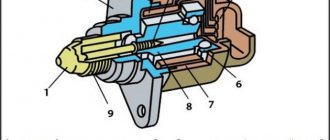
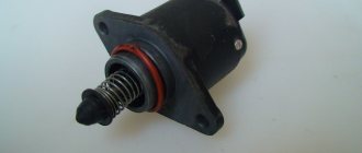
Idle air control device
The idle air control, РХХ-60, consists of the following parts, shown at the top in the figure:
- Plug block - 1;
- O-ring - 2;
- Fastening washer - 3;
- Armature axis mounting flange - 4;
- Armature winding - 5;
- Rotary glass - 6;
- Magnet - 7;
- Housing - 8;
- Fixed anchor - 9;
- Armature axis - 10;
- Magnetic core - 11;
- Bearing retaining ring - 12;
- Ball bearing - 13;
- Bearing seal - 14;
- Inlet pipe - 15;
- Rotary valve - 16;
- Emphasis - 17;
- Roller bearing - 18;
- Damper shaft - 19;
- Output pipe - 20;
- The letter x indicates a permanent connection
What is high engine speed
High revolutions can be defined as the engine working too hard, which is a deviation under idle conditions. In this situation, irregular distribution of fuel occurs, overheating of the unit
It is important that at the moment of startup, high speeds are not considered a breakdown. But after that they must fall
High rpm can be determined in three ways:
- look at the tachometer. If its readings at idle speed exceed 950 rpm, it’s time to be alarmed. Although lower indicators may also be a cause for concern: it all depends on the design features of the internal combustion engine; if other indicators are the norm, this will be indicated in the technical passport;
- by ear (if the speed increases, the internal combustion engine begins to operate more noisily);
- a car with an injector has a special indicator on the dashboard (“Check engine”), which will light up in case of deviation.
Tachometer shows engine speed
Diagnosis of IAC
Ideally, diagnostics of the regulator should be carried out on a stand that can reproduce the pulses of the on-board computer. In practice, this is expensive; low-cost verification methods are used. In any case, the algorithm of actions at the initial stage is the same:
- the handbrake is applied, anti-recoil devices - shoes - are installed under the wheels;
- disconnect the “-” terminal from the battery;
- knowing where the TPS and MAF sensors are located, the location of the IAC is determined;
- the valve is disconnected from the on-board computer (the plug is pulled out of the connector).
Valve removal
Further steps differ for different verification methods.
Manual check
The simplest method for checking IAC in an electronic intake distribution system is manual diagnostics (an assistant will be required):
- the IAC plug is disconnected from the connector;
- two screws are unscrewed and the device is dismantled;
- the regulator is reconnected to the ECU, but remains in the hands of the master;
- The assistant starts the engine, at this time the rod should be completely retracted into the coils, then, having received an impulse from the computer, extend a certain distance.
Manual IAC check
In other words, the functionality of the stem is checked, the owner makes sure that this part is not bent or jammed inside the valve. However, this does not provide a 100% guarantee that this IAC modification fully complies with the controller ECU firmware. The needle extends, but by an unknown amount. In the first case, the connector is checked, in the second - the plug; the markings are only on the plug.
In the classic version of checking “from simple to complex,” this stage is the initial stage; then you should check the integrity of the wires and coils, the condition of the bypass channel, and needle wear. Only after these steps can you assemble a homemade stand with a pulsed voltage supply for comprehensive diagnostics of IAC.
Diagnostics with a multimeter
At this stage, you will need an IAC tester, which is checked with this device in two modes:
- ohmmeter - when connecting contacts C – D and A – B with the multimeter probes, the resistance should have a value of 40 – 80 Ohms, D – C and A – D should be equal to infinity;
- with a voltmeter - when the ignition is turned on, the voltage reaches 12 - 20 V.
proverka-testerom
Pulse testing on a homemade stand
Since the stand costs 1,500 - 1,800 rubles, and the regulator 300 - 500 rubles, purchasing the device is not economically profitable for the average user. A simple circuit without microchips is shown below:
- it uses 6 V charging from any mobile device;
- plug blocks are commercially available;
- First you need to disconnect the IAC from the on-board controller, then check the stroke of the rod;
- a bright glow of the lamp in the diagram indicates a malfunction of the rod itself;
- If the lamp burns at the incandescent level, the unit is considered to be in good condition.
Diagram of the device for checking IAC
Using a cleaning agent will restore the functionality of the rod, but only if it is clogged. If this part is bent, the entire regulator will need to be replaced.
Operating principle of IAC
The sensor installed on the engine (mass air flow sensor) determines the volume of incoming air and sends a signal to the ECU, which “gives a command” to “send” the required amount of fuel to the injectors. At the same time, the control unit takes readings from the crankshaft position sensor and controls the operation of the IAC. The last action is expressed in issuing a “command” to open an additional channel.
Another function of the IAC is to adjust the idle speed (700-900 per minute) depending on the engine warming up. If the temperature is insufficient, the ECU “orders” the sensor to increase the passage of the channel: as a result, more air enters the combustion chamber, and the control unit simultaneously supplies more fuel - as a result, the speed increases and the power unit warms up faster. In the same way, using IAC, the ECU takes into account changes in the load on the engine associated with the connection of additional consumers: for example, headlights, interior heater, heated rear window, mirrors, seats, etc. As a result, the engine operates stably at any load.
Signs of malfunctions
The IAC is not the most vulnerable element of the engine, but its failure is quite possible.
But the IAC belongs to the category of automotive actuators, and therefore, if it breaks down or a malfunction occurs on the dashboard, the Check light does not light up.
Regulator malfunctions can be identified by the following symptoms:
- When the internal combustion engine is at idle speed, the engine behaves unstable. Sometimes the engine may stall spontaneously if the speed is not maintained with gas.
- Without any reason, the speed increases or decreases.
- When changing any gear, the engine may stop completely. A similar situation can occur when starting from a standstill.
- When a cold engine starts, it does not operate at high speeds.
- When you turn on the headlights or the interior heater, the idle speed drops.
Cleaning the regulator or completely replacing it can help troubleshoot problems. Cleaning and then rinsing the part yourself is not difficult, nor is changing the element. But in both cases it is better to first dismantle the controller.
To do this, turn off the engine and remove the negative terminal from the battery. Next, the regulator contact connector is disconnected, the housing mounting bolts are unscrewed, and the problematic element is dismantled.
Cleaning does not help in all situations. Before installing a remanufactured or new regulator, the flange O-ring should be lubricated using engine oil.
It is quite easy to calibrate the unit with your own hands. To do this you need:
- check the distance from the mounting plate to the end of the rod and make sure that it does not exceed 23 mm;
- disconnect the minus from the battery;
- install a new valve;
- return the negative terminal to its place;
- turn on the ignition for 5 seconds, but do not start the engine;
- wait for automatic calibration;
- turn off the ignition;
- fully start the engine and watch how it idle.
The XX regulator is an important component of any engine. At the same time, its diagnosis, replacement and repair should not cause any particular difficulties even for a beginner.
The most typical symptoms of a malfunctioning idle speed sensor
You can determine them immediately after starting the engine: first of all:
- the motor may “catch” and stall immediately after a successful start;
- unstable operation of the power plant when it warms up (idle speed floats both “cold” and “hot”);
- after starting the power plant, its speed does not increase in order to quickly reach the required degrees;
- after the engine reaches the standard temperature, a spontaneous increase or decrease in the idle speed is observed;
- when connecting electricity consumers - headlights, heater, air conditioner, etc., the crankshaft speed drops and does not stabilize.
- the car jerks while driving at low engine speeds;
- After switching from a higher gear to a lower one or vice versa (neutral position of the gearbox), the engine may stall while driving.
It is worth noting here that all of the above signs can appear either individually or simultaneously. In this case, the “Check” lamp may not respond to problems with the idle speed sensor (which is what happens in most cases). If an error is displayed on the instrument panel, this indicates a malfunction of the TPS - damper sensor.
Causes of malfunctions
Most often, the valve does not work due to dirt accumulated inside the bypass channel. Much less often, the integrity of the solenoid windings is damaged. It could also be:
- inconsistency between the ECU firmware and the IAC variety (typical for injection engines).
- excessive needle wear;
- break in the coil;
- lack of winding contacts with leads inside the sensor.
Speed and revolutions: fuel savings and engine life
So, you can often hear from drivers that as soon as the car accelerates to 60 km/h, you can engage, for example, 5th gear (if the gearbox is 5-speed). In this case, the speed will drop to 1900-2000 thousand rpm and in this mode fuel consumption will be minimal. In other words, the most economical option is to drive when the highest gear is engaged and the speed is low.
If you study the theoretical part a little, accelerating to a certain speed will require energy expenditure. The more intense the acceleration occurs, the more energy is consumed. After reaching a constant speed (cruising), fuel consumption becomes less, but it must be taken into account that the car also overcomes air resistance.
Without going into mathematical calculations, an increase in speed, for example, from 50 km/h to 100 km/h will mean that air resistance increases not by 2 times, as many might think, but by as much as 8 times. That is, to maintain the current speed, you will need to expend 8 times more energy. It is to overcome air resistance that engine power is expended.
It turns out that to maintain a speed of about 50 km/h, you need about 30-35 hp, while when accelerating to 120-130 km/h, 80-90 “horses” are needed to overcome resistance to air flows. To this you need to add the mass of the car itself, which is different for each vehicle, make allowances for road conditions, etc.
You also need to remember that piston internal combustion engines demonstrate the best efficiency in the zone of maximum torque, and not maximum speed. At the same time, it should be taken into account that the gearboxes are also different and have different gear ratios.
It becomes clear that the most economical mode is actually achieved when the car is moving in top gear at a low speed, but the optimal speed in such a gear will be different for each car.
Another important point is, let’s say, the feasibility of saving fuel in this way. In the manual, many car manufacturers specifically indicate that you need to switch to the highest gears not at 50, but at 80 or even 100 km/h. The fact is that the lower the engine speed, the more the consumption drops, however, such driving at low speeds and in high gears can harm the engine.
For example, a 2.0 liter engine in a car weighing about 2 tons, which is moving in high gear at a speed of about 60 mph, will operate at low speed. In this case, the load on the motor will be very large. The fact is that the oil pressure at low speeds is also low, that is, the wear of parts and components of the power unit is maximum.
To reduce the load, you need to either add speed and increase the speed, or switch to a lower gear. If a car with the same engine weighs, for example, 1.3 tons, the load on the internal combustion engine will be less than in the case of a two-ton car, but accelerated engine wear will still be present.
If we summarize the information received, then it becomes clear that the lower the speed and the higher the gear, the lower the fuel consumption. At the same time, driving at low speeds “kills” the engine. This results in very dubious savings on fuel, which in no way covers the costs of engine repairs in the future.
Types of regulators
Externally, the unit looks like an electric motor equipped with a conical needle. There are several variations of the part:
- stepper - consists of a ring magnet and windings. The main rotor is rotated by stepwise supply of energy to the circuit components using electromagnetic force. The movement of the rod is carried out by an actuator taking into account the location of the rotor;
- solenoid type - the simplest type. The supply of energy to the winding activates the core. It moves into a special hole, reducing the diameter of the air channel. As a result, the supplied air volume decreases. Due to its simplicity it has the lowest cost. Its operation is carried out only in the open or closed position;
- rotary - the intake of air mass is controlled using frequency pulses, the main load goes to the rotor. The device resembles a solenoid regulator.
Types of idle speed sensors
The simplest version of the device is made on the basis of a solenoid - a coil. When voltage is applied to its windings, the core inside jumps out and fits into a special socket, reducing the diameter of the passage channel. As a result, the air supply volume decreases. The simplicity of the design of this type of idle air control guarantees its low cost. But there is also a serious disadvantage: the impossibility of fine-tuning the throughput of the additional channel. This is due to the fact that the idle air control valve only functions in the open or closed position.
There is another type of IAC - rotary. The operating principle of this device is similar to the previous one. But there is an important difference: the opening and closing of the bypass channel is carried out by a rotor, which ensures smooth operation of the regulator. However, today the stepper device has gained popularity. Its design includes a ring magnet, a rotor and 4 windings. Each of them receives voltage from the ECU. As a result, the rotor rod begins to rotate, which is screwed into the channel, blocking it to the desired value.
General principles of carburetor adjustment
Before adjusting the idle speed, ensure that both the fuel system and the ignition system are working properly - we set the ignition timing using a strobe light, and clean the carburetor if deposits are already noticeable in it. The cross-section of the fuel and air channels is small, and pollution in them is most noticeable. You need to be sure that there are no air leaks through cracked vacuum pipes or the brake booster; on Solexes, a well-known disease is warping of the carburetor mating plane to the manifold, which causes a lot of air to be sucked in, especially at idle.
Before making adjustments, we warm up the engine, since stable operation of a cold engine is ensured by the starting system. If we adjust the idle speed on a cold engine, then at operating temperature we will get high idle speeds and an over-rich mixture.
It is necessary to ensure the correct fuel level in the float chamber - the composition of the mixture depends on it in all engine operating modes. In addition, this adjustment will have to be performed on a disassembled carburetor, so we combine it with cleaning.
To adjust the level, the top cover of the carburetor is removed, after which it is turned over - the mating plane to the body must be horizontal. There are several ways to measure and adjust the level. Carburetor masters used this template for Solexes, which allowed them to immediately determine whether the level needed to be adjusted and set it without any measurements:
By pressing the template (4) against the gasket (3) placed on the carburetor cover (2), control the gap between the template and the floats (1) - it is 1 millimeter. In case of deviations, the required gap is set by bending the tongue (5), pressing on the locking needle.
Without a template, use a ruler or caliper, setting the level of the top edge of the float to 34 mm.
With “Ozons”, when adjusting, the full stroke of the float (9) is set at 8 mm by bending the stop (3), and the gap between the fully lowered float and the spacer (10) is set to 6.5 mm using the tongue (8) pressing on the needle (4).
In addition, we perform the initial adjustment of the dampers, unlike the Solex, where the quantity screw directly controls the throttle position. The throttle stop screw of the first chamber is turned out until a gap appears between it and the drive sector, then it is screwed in until it touches and then another 90 degrees (a quarter turn). The throttle screw of the second chamber is installed until it touches; when adjusted correctly, at idle the throttle in the first chamber is slightly open, and in the second it is closed (this chamber is completely turned off at idle).
At Solex, you need to make sure that the EPH valve on which the idle jet is installed is correctly tightened. We tighten the valve until the nozzle lightly touches the seat. An undertightened jet will cause a deviation in the composition of the emulsion supplied to the idle system, but it cannot be overtightened: the seat is damaged, making precise adjustment of the idle speed impossible (the second “proprietary disease” of front-wheel drive carburetors).
Something else useful for you:
- What to check if the engine stalls at idle
- Floating idle: how to stabilize floating speed
- Engine knocking: what to do and how to determine the cause
Principle of operation
At its core, the idle air valve is an electromechanical actuator operating under the control of an electronic unit that supplies electrical signals to open or close it.
In this case, the diameter of the flow section of the XX channel changes, supplying the required amount of fuel or air to the engine intake manifold.
Carburetor engines.
In gasoline carburetor engines, the XX solenoid valve is installed directly in the carburetor body and is part of the forced idle economizer system (ISP) of the fuel system.
The operation of the XX valve is controlled by the EPHH control unit installed in the engine compartment of the vehicle.
When the ignition is turned on, power is supplied from the control unit to the solenoid valve, which opens and supplies gasoline through the XX channel into the engine intake manifold.
When the ignition is turned off, the idle air valve is de-energized and cuts off the fuel supply.
To adjust the amount of fuel supplied through the idle passage, an adjusting screw called the “idle screw” is installed in it.
Injection engines.
In gasoline injection engines, the idle air valve, more often called the “idle control valve,” is mounted in the throttle body and is part of the electronic engine control system (ECM).
Its operation is controlled by an electronic ECU (controller), located, as a rule, in the car interior under the front panel.
The control unit records signals from sensors that monitor individual engine operating parameters, processes the received information and issues a control signal to the idle speed controller.
Upon command from the ECU, the XX regulator increases or decreases the volume of air supplied through it to the engine inlet manifold, ensuring the specified XX speed.
Diesel engines.
In diesel engines, the idle air valve is installed in the housing of the high pressure fuel pump (HPF) and, just like in the injector, is connected to the engine ECU control unit located in the engine compartment.
But at the same time, it regulates the supply of fuel, not air, to the cylinders, providing the necessary idle speed.
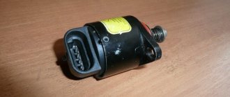
Checking the sensor yourself
To dismantle the IAC, you need to disconnect the block and unscrew two screws.
Before dismantling, you need to thoroughly clean the place of its attachment from dust and dirt and remove the negative terminal from the battery. But first, a check.
Sensor connection diagram.
We look at the connection diagram and check the sensor using a conventional multimeter in the following sequence:
Check for power supply to the sensor. To do this, measure the voltage at the two outer contacts of the block, A and D. Turn on the ignition, place the black probe of the multimeter on the engine ground, and the positive probe on the contacts one by one. The voltage should be within 12 Volts. If it is less or absent altogether, we look for an open circuit or blame the electronic control unit for everything. But first, we check the voltage at the terminals from ECU 4 and 54. Here, naturally, there should also be 12 V.
The voltage is normal.
We switch the multimeter to ohmmeter mode and measure the resistance between contacts A-B and C-D on the sensor itself. As can be seen from the diagram, we are checking the resistance of the winding of the stepper motor of the regulator. Between the indicated contacts, the nominal resistance is from 40 to 80 Ohms, according to the factory rating - 53 Ohms.
We check the electric motor for short circuit of the windings. To do this, measure the resistance at terminals A-D and B-C. The resistance should tend to infinity, that is, there should be no contact between the two windings
If there is resistance, no matter what the value, we conclude that the windings are short-circuited. This cannot be cured; we replace the sensor with a new one.
It cannot be said that this testing method 100% guarantees the functionality of the sensor; we only checked its electrical part. The mobility of the cone valve and the magnitude of its stroke are of great importance. And this can only be checked either at a special stand or with a special tester.
Checking the operation of the mechanical part of the sensor
To check, remove the sensor from the throttle assembly.
However, if the electrical part is in order, you can check the mechanical part of the regulator by eye:
- Unscrew the sensor and remove it from the throttle body.
- We connect the contact block to the sensor.
- Turn on the ignition. When turned on, the valve should move forward. If this does not happen, the rod is coked or the stepper motor is not working properly.
- We measure the distance between the sensor body and the conical valve - nominal 24 mm.
We measure the distance with a caliper.
If we removed the sensor from the car and the electrical test passed, but we still did not achieve mobility of the cone valve, we try to clean the regulator using a soft swab, a cotton swab and WD-40 penetrating lubricant or an aerosol carburetor cleaner. Good luck to everyone and stable idle speed in any weather!
Sensor with carbon deposits.
Soak the valve in cleaner.
Cleaned sensor.