Wiring diagram GAZ 31029: technical parameters
Did you like the article? Follow our channel for new ideas of useful car tips. Subscribe to us in Yandex.Zen. Subscribe.
The successor to the traditions of a representative domestic car, without any doubt, was the GAZ 31029, which inherited “all the stuffing” from its predecessor, the GAZ 24-10.
But in fact, in modern terms, in 1992 the famous Volga underwent a long-awaited restyling.
Note! Despite the almost complete unification with the previous model, the car turned out to be in demand on the market, and in less than five years of production, 830 thousand cars rolled off the factory assembly line.
Electrical wiring GAZ 3110: for carburetor and injection options
Did you like the article? Follow our channel for new ideas of useful car tips. Subscribe to us in Yandex.Zen. Subscribe.
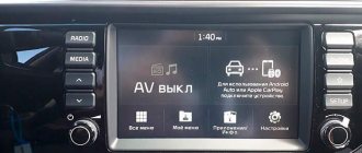
Appearing in the car plant's production program in 1997, the GAZ 3110 model was supposed to improve sales volumes, since the modernization of its predecessor meant not only improving the appearance, but also modernizing the interior. As a result, the car's interior began to resemble the trim of foreign models in the mid-price range, including increased functionality.
Prerequisites for success
It should be admitted that the refreshed exterior, coupled with the interior of a taxi based on the GAZ-24, familiar to most Russians, attracted additional buyers. The influx was ensured by cooperators and entrepreneurs who were actively developing in those years and were looking for an opportunity to improve their social status. (see also the article Features of the GAZ 3307 electrical wiring diagram)
And the rejuvenated Volga came in handy. Moreover, the release of this model allowed the enterprise itself to literally “survive” - selling prices covered the costs of the giant plant even in the conditions of inflation, which the whole country found itself in in the 90s.
For reference! Despite the low build quality inherent in the entire auto industry in the post-Soviet period, this car had the honor of becoming a record model - the production volume of GAZ 31029 reached 115 thousand cars per year. In the entire history of the plant, no other model could break this record.
Technical specifications
Power unit
Structurally, the new model inherited all the main components and assemblies of its predecessor.
In particular, in the first years of production the car was equipped with:
- ZMZ 402.10 – in-line gasoline engine with a volume of 2.5 liters and a power of 100 hp;
- Later, a 16-valve ZMZ 4062.10 with a power of 150 hp appeared, which had 2 camshafts in the valve cover (the old engine had a lower location).
But for a number of parameters, both the new and, especially, the old power units could not compete with foreign models, which forced the automaker to look for engine suppliers abroad. (see also the article Features of the Niva Chevrolet wiring diagram)
- In 1995, a pilot batch was produced with a Rover power unit. It was an inline sixteen valve 2.0 liter “four” with a capacity of 136 hp;
- In 1997, the automaker equipped the model with a Japanese-made engine from Toyota. These were 4- and 6-cylinder in-line gasoline engines from the Land Cruiser model, as well as a 2.5-liter diesel engine from the Crown model;
- The Chrysler engine appeared in the factory program after the price of power units produced by ZMZ increased, and GAZ was not ready to buy them at such a high cost.
For reference! Most often, the installation of Japanese-made engines was carried out in private companies in Moscow and St. Petersburg. Due to difficulties with spare parts and maintenance, they were not widely used in the Russian outbacks. As for Chrysler engines, today GAZ produces them according to purchased drawings and installs them in series.
Electrical equipment
Following the ZMZ engine, the GAZ 31029 electrical wiring also migrated from the donor car:
- The ignition system exactly repeated the GAZ 24-10 circuit;
- Installation of imported engines required reconfiguration of the vehicle systems;
- The instrument panel that appeared later with electronic devices on stepper electric motors also changed the interior electrical circuit. (see also the article Features of the GAZ wiring diagram)
Note! Any instruction for Volga cars refers to a specific power unit, since maintenance and repair directly depend on the installed engine model.
Features of the modification
The designers took into account the weaknesses of its predecessor, the GAZ 3102, and equipped the new model with:
- Electric headlight range control;
- Heated windshield washer nozzles;
- Dual-mode heated rear window.
This required changes to the electrical wiring, as a result of which it was retrofitted with additional harnesses and connectors.
However, more serious changes affected the use of contactless ignition, resulting in:
- The engine compartment wiring diagram of the GAZ 3110 was thoroughly redesigned;
- The use of more powerful pulses in the electrical network forced designers to change the contacts of most electronic devices (see also the UAZ 31512 wiring diagram).
Tip: when servicing a car with your own hands, the use of sandpaper or any other abrasive material to clean contacts is prohibited. The fact is that any foreign particle caused the contacts to not fit tightly, which immediately led to their burning and failure.
Carburetor engine
At the time of the release of the GAZ 3110, the automaker had only one power unit capable of providing the car with acceptable speed characteristics. This is a ZMZ-402 with a volume of 2.4 liters.
It had some differences:
- The ZMZ-402.10 modification was designed to run on gasoline with an octane rating of 92;
- The version for taxis and for the Gazelle family was designed for gasoline with an octane rating of 76.
For reference: Since the price of gasoline was different, and the car itself was quite “gluttonous,” many owners converted the engine to run on 76 gasoline in order to reduce operating costs.
Injection option
The 2.3-liter in-line gasoline engine with controlled fuel injection ZMZ-406.2 was considered more progressive (see also Niva 21213 wiring diagram).
To improve its characteristics, an electronic ignition system was installed on the car, which had many new products for the domestic automobile industry:
- Electronic control unit (ECU) with the ability to display error codes;
- Two ignition coils;
- Electronic switch.
Evolution and modernization of GAZ-3110 cars: features of the electrical circuit
Every car owner should understand the electrical circuit of his car. This knowledge will help, if necessary, repair the wiring and find the fault. Despite the fact that domestically produced cars are not equipped with as many instruments and devices as imported cars, their circuits are also quite complex. What is the electrical circuit of the GAZ-3110, what malfunctions are typical for it and what you need to know about prevention - read in this article.
Repair of GAZ-31029
Many domestically produced cars have breakdowns more often than foreign cars. This is an axiom. With poor quality road surfaces, anything can happen in a car. If the owner of a car is not familiar with its internal equipment, then most often he has only one option - to the service station. But, if you have a repair manual, and your hearing perfectly distinguishes the sounds of a breakdown, then there is no difficulty in repairing it with your own hands. It is possible to repair everything in the GAZ-31029 car, and even modernize it.
Features of electrical equipment
The GAZ electrical equipment diagram includes the following subsystems:
- engine starting system;
- ignition, which includes a distributor, spark plugs, coil, etc.;
- external car lighting, including fog optics, light alarms and turn signals;
- dashboard;
- interior lighting, as well as all devices installed in it;
- heating system - stove;
- windshield wiper unit;
- headlight adjustment device;
- microprocessor-based engine control system;
- mounting block of safety devices.
Photo gallery “Subsystem connection diagrams”
Gas ignition switch circuit 31029
Pickup
- from the Auto Parts store at the address: Moscow, st.
Kominterna, no. 20/2, directions ( CHECK AVAILABILITY BEFORE ).
Our delivery rates
auto parts for individuals persons:
- in Moscow within the Moscow Ring Road, to the city: Mytishchi - 500 rubles.
- in the Moscow region - 500 rubles. + 40 rub. per kilometer.
- in Russia - at prices of third-party transport companies (shipping, SDEK, TC Energia and others).
Delivery for legal entities with an order value of 15,000 rubles. in Moscow FREE
!
To pay by bank transfer, send us the details of your organization by e-mail.
Moscow, st. Comintern, 20/2. Tel.,
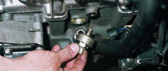
Possible wiring faults
What malfunctions in the wiring of a GAZ 31105 with a Chrysler engine, GAZ 31029 or any other model can occur:
- Lack of contact. Such a malfunction may be associated with a break in the electrical wiring, oxidation of the outputs, or their burning. If the contact is oxidized, then it needs to be cleaned, if the wire is broken, then it must be restored, if the reason lies in burning, then first you need to eliminate the problem of overvoltage. It is quite possible that the connector simply came out of the socket; this often happens when the plug is poorly secured and constantly driving on uneven roads.
- Battery discharge. This problem most often occurs in the cold season - in the cold, batteries are most susceptible to discharge. If this happens during the warm season, then you need to check the battery charge, the level and density of the electrolyte, as well as the case for damage.
- Circuit break. A malfunction of this type is diagnosed by searching for the damaged area manually or using a tester. The break must be eliminated by replacing the wire, and the replaced wire should also be wrapped with electrical tape - this will create an additional layer of insulation. When laying wires, make sure that they are not exposed to moving mechanisms, otherwise this will lead to another insulation breakdown and breakage.
- Burnout of the safety element. This problem is most relevant for cars that have power surges in their on-board network. If the voltage surges are noticeable, then the fuse simply will not be able to withstand the load, which will lead to its failure.
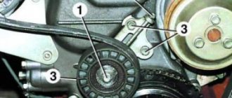
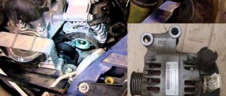
Generator circuit for Volga and Gazelle with engine 402
For Volga engines, generators were equipped with a double-row pulley, for Gazelles - with a single-row pulley.
For cars produced in the first half of the 90s, an alternating voltage output from the generator phase was used to operate the tachometer.
In subsequent models, the tachometer received a signal from the ignition system, and the generator phase output was no longer needed; if the generator has one, it is simply not connected.
The generator has a traditional circuit. Winding, rotor, diode bridge, brush assembly. The voltage regulator type 13.3702 (131.3702) is separate and connected to the generator by wires.
Generator diagram for Volga with engine 402
Generator circuit for a Gazelle with engine 402
The circuit differs in that it uses a voltage ammeter to monitor the operation of the generator.
When the ignition is turned on, current from the battery flows through the ignition switch contacts, from point 151, to the brush, then through the rotor winding to the external regulator (which is located away from the generator). A separate wire comes to the + terminal of the regulator from point 151, plus from this wire, opens the voltage regulator and the rotor current passes to ground. This current magnetizes the rotor.
The engine starts, the generator rotor begins to rotate, and its magnetic field excites an EMF in the generator winding. Already at idle speed the generator begins to produce voltage. The battery becomes a consumer and charging begins, the excitation winding of the generator is powered through the same circuit, only now not from the battery, but from the generator output.
When connecting external consumers, everything is powered by the generator.
- Operating principle of the generator
- The rectifier (diode bridge) consists of six diodes that conduct the winding current in only one direction, this is how rectification occurs.
A magnetic field is created by an electric current. To do this, a winding is inserted inside the rotor, which is called the field winding. Current is supplied to the field winding through brushes pressed against the rotor rings.
Voltage regulator
The generator must provide a constant voltage level in the network. The higher the speed, the greater the EMF, which means the voltage can rise to unacceptable values. Therefore, all automobile generators are designed to maintain voltage at a given level when the engine speed changes.
In addition, when the devices are turned on, the load current increases and the higher the current, the lower the voltage becomes. A device that maintains voltage at the same level is called a voltage regulator. The voltage regulator is included in the field winding circuit; it turns the field current on and off.
What should the voltage be?
All electrical equipment is designed for a battery voltage of 12 Volts. To charge the battery, the generator voltage must be maintained approximately 2 Volts higher, so the operating voltage of the generator is maintained at 14.2 – 13.8 Volts.
If the voltage is higher, this will lead to the battery boiling out and shortening its service life, light bulbs and other devices will begin to burn out. If the voltage is lower, the battery will be undercharged, resulting in unexpected starter failures and shortened battery life.
The voltage at a given level is maintained by the voltage regulator.
- If the generator is faulty, the battery is discharged or poorly charged.
- This makes the following cases possible:
- The starter turns hard, but still starts.
- The starter turns hard, cannot start the engine and there is not enough battery for the second attempt.
- In the morning, the starter turns slowly and has difficulty starting the engine.
- The car will sit and you won’t be able to start it again.
- Pusher starts only
- Everything went dark and there was complete silence.
- The lights are dim and the signal is weak
- If the voltage rises above 15 Volts, this is already an overcharge
- The battery becomes wet and smells of acid
- Typically, overcharging occurs if the voltage regulator is broken; on Volga and Gazelle this is an external device and is easy to replace.
- What to do if the voltage drops and there is a suspicion that the generator is not working.
To understand what's going on you need to start the car. For example, install a test battery, or push start it.
The problem could be: the starter, the battery, the wiring or the generator. First you need to install a test battery. If it starts normally, then the starter and wiring are normal. Let's check the generator. The needle on your own voltmeter should be on the green scale. You need to check the voltage on the battery with a voltmeter.
The voltage should be 13.6 - 14 Volts; when the headlights and heater are turned on, it should not drop below 13.4 Volts. If so, then the generator is working. If the voltage is lower, then charging is weak or absent. First you need to make sure that the belt is tensioned well. Then measure the voltage at the generator output, it should be 13.6 - 14 Volts.
If it is lower on the battery, then the 60 A fuse is broken, or the fuse block contacts are rusty.
This is a common problem on old Gazelles. The charging current goes from the generator plus to the battery plus through a 60A fuse. This place quickly rusts and a whole volt or one and a half drops at the fuse contacts. It is better to install a new power fuse block.
If the voltage at the generator output is close to 12 Volts, then the generator does not work, there is no charging and the battery runs out.
Let's change the voltage regulator and install a test one. If the generator starts working and normal voltage appears on the battery, then everything is clear, you just need to change the voltage regulator. We buy regulator 13.3702 or its equivalent. If replacing the regulator does not help, then the problem is in the generator itself or in the wiring.
Wiring prevention
What you need to know about electrical network maintenance:
- The use of homemade coin fuses, pieces of wire, etc. is not allowed. This problem can lead to a short circuit; in more severe cases, it can cause a fire.
- Remember that a car battery requires periodic maintenance. At least once a year you need to recharge the battery, you should also diagnose the density of the working fluid in the banks and its level. If you notice that there is little electrolyte in the banks, then you need to replenish its level.
- If you install an anti-theft system, DVR and other devices yourself, then make sure that the wire connection is of high quality and reliable.
- If problems are discovered in the operation of electrical equipment, they must be resolved as quickly as possible. If necessary, contact an electrician.
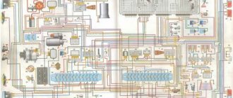
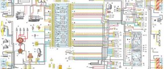
Simple electrical circuit gas 31029 402 engine color
B1 – oil pressure indicator sensor; B2 – emergency oil pressure indicator sensor; B7 – coolant temperature indicator sensor; B8 – engine overheat sensor; B12 – fuel level indicator sensor; B20 – cooling system fan thermal switch; B46 – speedometer sensor; B67 – brake fluid level sensor; B68 – sensor-distributor; B93 – carburetor air damper warning lamp sensor; D4 – EPHH control unit; E1, E2 – left and right headlights; E3, E4 – left and right fog lights; E7, E8 – left and right direction indicators; E9, E10 – left and right side turn signals; E16 – interior lamp; E27, E28 – left and right rear lights; E30, E72 – license plate illumination; E35 – engine compartment lighting; E59 – cigarette lighter; E61 – trunk lighting; E71 – glove compartment lighting; E80 – additional brake light; E81, E82 – rear light in the trunk lid; F1-F4 – spark plugs; F41 – left fuse box; F42 – right fuse box; F43 – fuse box in the engine compartment; G1 – generator; G2 – battery; H1, H2 – sound signals; H7 – emergency oil pressure indicator; H8 – overheat indicator; H16 – right turn indicator; H17 – left turn indicator; H19 – fuel reserve indicator; H20 – high beam headlight indicator; H30 – indicator of the engaged parking brake; H54 – generator malfunction indicator; H56 – brake fluid level drop indicator; H62, H63 – front side lamps; H64, H65 – headlight lamps; Н66–Н69 – backlight lamps; H70, H71 – rear fog lights; H72, H73 – reversing lights; H74, H75 – brake lights; H76, H77 – rear side lamps; H78, H79 – rear direction indicators; H80 – side light indicator; H81 – backup control lamp; H92 – carburetor air damper warning lamp; H97 – seat heating indicator; K1 – starter relay; K3 – windshield wiper relay; K7 – sound signal relay; K12 – turn signal relay; K13 – parking brake indicator relay; K20 – fog lamp relay;
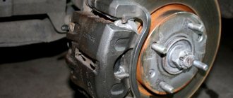
Repair GAZ 3110 (Volga): Checking and replacing generator brushes
You can check and replace the brushes without removing the generator from the car.
| EXECUTION ORDER | |
| 1. Disconnect the wire from the negative terminal of the battery. | |
| 2. Disconnect block 1 with wire from the brush holder terminal. Unscrew two screws 2 and remove brush holder 3 from the generator. | |
| 3. Check the ease of movement of the brushes in the brush holder. If the brushes are jammed, you need to remove the two mounting screws and remove the brush holder cover. Clean the brushes and clean the holes in the brush holder. If it is impossible to achieve the required result, replace the brush holder assembly or brushes. Brushes with chips, cracks or other defects must also be replaced. | |
| 4. Check the amount of protrusion of the brushes from the brush holder. If the value “a” of the protrusion of the brushes in a free state is less than 8 mm, replace the brush holder assembly or brushes. |
Electrical equipment GAZ 3110
As in any car, the GAZ 3110 electrical circuit contains automotive wiring with connectors, various relays and sensors, fuses, instruments, as well as energy sources and consumers. Energy sources are a generator and a battery; consumers include:
Starter design diagram for Gas 3110
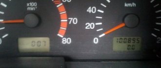
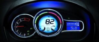
The Volga 3110 has an electronic speedometer. It should be noted that on the previous GAZ 31029 model the speedometer was equipped with a mechanical drive (cable). Also, unlike the 31029, the 3110 model now has a tachometer.
But the new device cannot immediately work on a GAZ car without problems, and therefore various problems arose with the speedometer and tachometer.
The tachometer in the first models had the following flaw - the instrument needle trembled, indicating the number of revolutions. Later, the manufacturer brought the device to perfection, and the owners of the first cars had to fix the defects with their own hands - solder an additional resistor into the tachometer circuit.
Tachometer from Volga 3110
Further modernization
Plans to increase sales volumes were not destined to come true. There are several reasons for this:
- Quite high costs of operating a GAZ car with low functionality;
- Obsolescence of the design in terms of passive safety;
- Poor body corrosion resistance;
- Lack of comfort features.
All this forced the automaker to engage in deep restyling, as a result of which the GAZ 31105 model appeared in 2004.
Among its features it should be noted:
- DOНC power unit with a volume of 2.4 liters from Daimler Chrysler;
- Electronic throttle pedal;
- A new instrument panel, redesigned to meet safety requirements;
- A control panel for power windows and exterior mirror adjustment located on the driver's door;
- New headlights and taillights;
- Air conditioner.
All this led to the fact that the electrical wiring diagram of the GAZ 31105 changed radically. Although the car became more similar in functionality to its foreign counterparts, it nevertheless could not compete with them.
For reference: unfortunately, there were no further prospects for modernizing the GAZ 3110. And against the general background of falling consumer demand, the automaker decided to curtail their production. As a result, the GAZ 31105 modification turned out to be the last production passenger model of the Gorky Automobile Plant.
Electrical faults
Volgas have never been particularly reliable, and the electrical equipment on the car is far from ideal in quality. What are the main electrical faults found on the GAZ 3110:
Electrical diagram of the Volga 3110 windshield wiper
- On the 406th engine: the generator often “flies”, it is not always enough for 50 thousand km;
- the engine control unit is not very reliable;
- Domestic air flow sensors often fail;
- The phase sensors are not of high quality - because of it, fuel consumption increases.
- Switches overheat and fail;
Electrical wiring also often fails the owners of the 3110 - unreliable contacts can be in any connection. Fires in the engine compartment also happen due to wiring, although most often the car owners themselves are to blame for this. If there is dirt and oil under the hood, and gasoline is leaking from the fuel hoses, no car will withstand such careless treatment.
Gas 3110. Generator repair. Volga
Repairing a generator yourself is difficult and impractical, since a special stand will be required to determine its serviceability and compliance with its characteristics.
| NOTE During electrical tests of the generator, especially in the rectification stage, the equipment used should not produce voltages higher than 14 V to avoid the risk of destruction of some components. |
Therefore, it is better to entrust generator repair to qualified specialists at a service station, where you can also replace the generator from the exchange fund. Such a generator will be 50% cheaper than a new one.
However, before replacing the generator, you can carry out some checks.
Checking the voltage regulator
on a car
To check the voltage regulator, you must have a DC voltmeter with a scale of up to 15 - 30 V, accuracy class no worse than 1.0.
Check the voltage regulator installed on the car in the following order:
- start the engine and let it run for about 15 minutes at medium speed;
- using a voltmeter, measure the voltage between terminal “30” and the “ground” of the generator;
- The voltage should be between 13.3 - 14.6 V.
If there is a systematic undercharging or overcharging of the battery and the regulated voltage does not fall within the specified limits, the voltage regulator must be replaced. In addition, it is necessary to check the condition of the carbon brushes.
Checking the condition of the carbon brushes
Although this work can be done with the generator installed, it is still recommended to remove the generator from the vehicle.
Check the condition of the carbon brushes in the following order:
- unscrew the bolts securing the protective casing and remove it;
- unscrew the two bolts securing the voltage regulator;
- Carefully remove the voltage regulator assembly with brush holder and generator brushes from the generator housing;
- Check the condition of the contact part of the carbon brushes. Check the mobility of the brushes in the brush guides; if necessary, clean the brush holder with trichlorethylene.
- measure the length “a” (Fig. 9.4) of the carbon brushes protruding from the brush holder. If their length is less than 5 mm, then the brushes should be replaced.
The new carbon brush is 12mm long, so you can tell how much the carbon brushes have worn down. Replacing old carbon brushes with new ones means replacing the entire voltage regulator assembly with brushes and brush holder, since the carbon brushes are soldered into the brush holder. However, you can solder the electrical connection of the new carbon brush yourself if you wish.
The generator field winding is checked for open circuit and short circuit. Connect the tester (in ohmmeter mode) to the rotor slip rings (Fig. 9.5). The tester should show a winding resistance of 2.8 - 3.0 Ohms.
If the tester shows more resistance, then wipe the contact rings with a cloth soaked in trichlorethylene and clean them with glass sandpaper. If a groove with a depth of more than 1.5 mm has formed in the slip ring, then the ring must be re-sharpened on a lathe.