Explanation of symbols
Knowledge of the definitions of the 2107 Lada electrical circuit will help you quickly locate the required wire, diagnose it, identify and fix the malfunction. Of course, when replacing the cabin filter or changing the oil, such information will not be useful, but in specialized matters, deciphering the symbols will significantly simplify the repair process.
- 1 – headlights VAZ 2107;
- 2 – side turn signals;
- 3 – battery;
- 4 – starter activation relay;
- 5 – carburetor electro-pneumatic valve;
- 6 – internal carburetor switch;
- 7 – generator system 37.3701;
- 8 – gearmotors for headlight cleaners*;
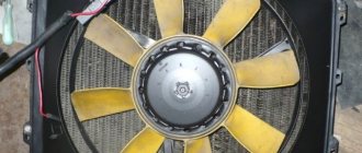
- 9 – fan motor activation sensor;
- 10 – electric motor of the engine cooling fan;
- 11 – sound signals;
- 12 – ignition distributor;
- 13 – spark plugs;
- 14 – starter;
- 15 — coolant temperature indicator sensor;
- 16 – engine compartment lighting;
- 17 – critical oil pressure indicator sensor;
- 18 – warning lamp for insufficient brake fluid level;
- 19 – windshield wiper electric motor;
- 20 – power system valve control unit;
- 21 – ignition coil;
- 22 – electric motor of the headlight washer pump*;
- 23 – electric motor of the windshield washer pump;
- 24 – mounting block;
- 25 – windshield wiper relay;
- 26 – hazard warning and direction indicator relay;
- 27 – brake light switch;
- 28 – reverse lamp switch;
- 29 – ignition relay;
- 30 – ignition switch;
- 31 – three-lever switch;
- 32 – alarm switch;
- 33 – plug socket for a portable lamp**;
- 34 – heater heater fan switch;
- 35 – additional switch for the heater electric motor;
- 36 – indicator lamp for turning on the heated rear window;
- 37 – indicator lamp for insufficient brake fluid level VAZ;
- 38 – signaling unit;
- 39 – electric motor of the stove fan;
- 40 – glove compartment lighting lamp;
- 41 – lamp switches on the front door pillars;
- 42 – switches for warning lights of open front doors***;
- 43 – alarm lights for open front doors***;
- 44 – connecting block;
- 45 – cigarette lighter;
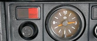
- 46 – hours;
- 47 – instrument lighting switch;
- 48 – diode for checking the serviceability of the warning lamp for insufficient oil pressure and brake fluid level;
- 49 – fuel level indicator;
- 50 – indicator lamp for insufficient gasoline level (fuel reserve);
- 51 – speedometer;
- 52 – control lamp for turning on the direction indicators on the dashboard;
- 53 – warning lamp for the carburetor air damper opening;
- 54 – indicator lamp for battery charge indicator;
- 55 – switch for signaling that the carburetor air damper is slightly open;
- 56 – instrument cluster;
- 57 – econometrician;
- 58 – lamp switches on the rear door pillars;
- 59 – coolant temperature indicator;
- 60 – tachometer;
- 61 – handbrake indicator lamp;
- 62 – low oil pressure indicator sensor;
- 63 – indicator lamp for high beam headlights;
- 64 – signaling device for turning on dimensions;
- 65 – voltmeter;
- 66 – parking brake warning switch;
- 67 – external lighting switch;
- 68 – rear window heating switch;
- 69 – rear fog light switch with on indicator*;
- 70 – fog light circuit fuse;
- 71 – interior lighting lamp****;
- 72 – rear lights;
- 73 – fuel level indicator and fuel reserve sensor;
- 74 – pads for connecting to the rear window heating element*;
- 75 – license plate lights.
* Some models have headlight and windshield wipers installed together. **Models up to 2000. ***Cars that came off the assembly line before 1998.
****One lamp in the center of the roof (before 2000) or two lamps located in the body pillars after this date.
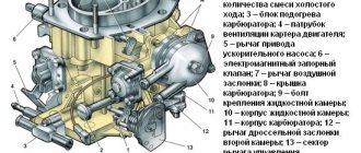
Electrical diagram of VAZ 2107 with carburetor
Since the production of the VAZ 2107 lasted from 1982 to 2013, many changes were introduced in the electrical circuit (including the appearance of new components), which entailed adjustments in the thickness and color of the wire insulation and their routing along the body. Below are electrical diagrams of a VAZ 2107 with various ignition systems.
Contact ignition system
Electrical diagram of a VAZ 2107 with classic ignition
Designation of components with descriptions shown on the electrical diagram:
- Headlight.
- Direction indicators located on the side of the front fenders.
- Battery 12 volt.
- Starter activation contact group.
- Electric valve on the carburetor.
- Limit switch.
- Generator model 372.3701. When installing generator 9412.3701, the connection diagram is identical.
- Drive for headlight cleaners (optional).
- Thermal sensor for turning on the fan drive.
- Electric fan drive.
- Klaxon.
- Contact distributor of ignition pulses.
- Candle.
- Starter.
- Liquid temperature measuring sensor.
- Underhood lighting.
- Emergency pressure indicator.
- Emergency brake fluid level indicator.
- Electric motor and drive gear for windshield wipers.
- Valve controller on the carburetor.
- High voltage coil.
- Headlight washer pump drive (optional, comes with item 8).
- Window washer pump drive.
- Switching block with relays and fuse links.
- Contact group of the electric windshield wiper drive.
- Contact group ensuring the operation of turn signals and hazard warning lights.
- End activator of brake lamps.
- Reverse gear indicator limit activator.
- Contact group ensuring the operation of the ignition system.
- Ignition on and off system.
- Steering column unit with three levers for switching operating modes of headlights, turn signals and windshield wipers.
- Button for activating the alarm system.
- Socket for connecting the connector of a portable lamp.
- Three-position heating fan intensity switch.
- A control resistance that provides a change in the rotation speed of the heater fan.
- Control indicator for the electric glass heating system.
- Brake fluid level drop indicator.
- Housing for installation of control indicators.
- Electric fan drive for the heater air system.
- Illuminated glove box on the instrument panel.
- Interior lighting switches installed on the B-pillars.
- Limit switches for open door warning lamps (found on cars produced before 1998). Since 1998, these switches are used only to turn on the two interior lamps mounted on the B-pillars.
- Door open lamps (used in conjunction with position 42).
- Connection connector.
- Cigarette lighter.
- Quartz clock mounted on the center console.
- Switch for operating mode of instrument lighting.
- A control diode designed to check the brake fluid level indicator.
- A device showing the amount of fuel in the tank.
- Gasoline reserve indicator indicator.
- Speedometer with mechanical drive.
- Indication of a working turn signal.
- Choke indicator (air damper used to enrich the mixture when starting a cold engine).
- Battery charging indicator.
- Choke limit switch installed under the damper drive handle.
- Instrument cluster assembly.
- An econometer showing the degree of vacuum in the intake manifold.
- Limit switches for interior lighting mounted on the rear pillar.
- Engine fluid temperature indicator.
- Speed indicator.
- Handbrake control indicator.
- Oil pressure drop indicator.
- High beam connected circuit indicator.
- Indicator that side lights and low beam are on.
- Voltage indicator in the on-board network.
- Limit switch under the handbrake lever, used to turn on the indicator on the instrument cluster.
- Switch for operating modes of dimensions.
- Key for selecting the rear window heating operating mode. The key contains an indicator lamp that lights up when the heating is turned on.
- Rear optional fog light switch. The key has an operation indicator.
- Additional fog light circuit fuse (comes with item 69). The fuse is located under the headlight mode switch.
- A single dome light, installed only on vehicles with a solidly molded ceiling panel. This ceiling is found on cars manufactured before the mid-90s. With the beginning of the use of a soft ceiling, the interior lights moved to the central pillars (position 41).
- Combined headlights on the rear of the car.
- A sensor installed in the tank that serves to determine the gasoline level.
- Wire connectors used to connect the rear window heating system.
- License plate lamps.
This is interesting: What is the difference between air conditioning and climate control?
The connector blocks are shown separately, indicating the contact numbers:
- position A - connectors for headlights, glass cleaning system and carburetor valve controller;
- position B - connecting block on the fuse block and steering column unit;
- position B - connecting the contacts of the turn signal control relay;
- position G - rear lights;
- position D - alarm mode switch.
On VAZ 2107 cars of the first years of production, the G-222 generator was used, which was later replaced by the more powerful and modern model 372.3701.
The table details the elements of electrical circuits of generators.
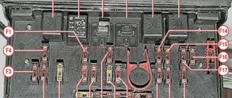
Conventional numbering of plugs in blocks
Additionally, to repair or tune a VAZ, you will need to know the serial numbers of the plugs in the blocks. The electrical diagram of the VAZ 21074 gives the following designations:
- Headlights, windshield and headlight wipers, power supply valve control unit, windshield wiper relay.
- Mounting block and three-lever switch.
- Signal and turn signals.
- Rear block lights.
- Alarm switch.
Additional designations
When connecting a generator or tampering with the wiring and ignition system of a VAZ, you should know the location of the fuse box in the car. There are 17 of them in total, of which 2 are reserve.
- reverse gear rear lamps;
- electric motors for headlight and glass washer pumps;
- heated rear window;
- direction indicators, hazard warning lights;
- fog lights;
- tachometer, voltmeter, warning lights on the dashboard;
- cigarette lighter and clock;
- sound signal;
- interior lighting, brake lamps;
- high beam headlights;
- high beam warning lamp;
- engine compartment lighting and license plate lighting;
- glove compartment lighting;
- low beam on the right;
- low beam on the left.
The electrical diagram of a VAZ 2021 car will help in repair and maintenance. You can download the image in high resolution using the link.
Carburetor engine
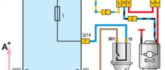
The operation of an engine with a carburetor has a classic scheme:
- When the ignition key is turned to the "Starter" position, the electronic system supplies power to it.
- The generator starts working.
- The generator transmits electric current to the coil. It is used to produce high-voltage currents. Low voltage currents are supplied to the coil. Passing through the module, they are transformed into high-voltage ones and transmitted via a high-voltage wire to the distributor.
- Using high-voltage currents, the distributor drive rotates the crankshaft of the power unit. He closes the contacts in order of priority and delivers an electric discharge to the spark plugs.
The principle of operation is reflected in the electrical circuit of an engine with a carburetor.
Classic wiring diagram - carburetor
Classic ignition
The contact system includes the following elements:
- switch;
- coil;
- distributor;
- high voltage wires;
- candles.
Thanks to the distributor, the circuit of the primary winding of the ignition module is interrupted, and then the high-voltage current is distributed in the required sequence to the spark plugs. With the help of a coil, low voltage current is converted into high voltage current. The spark plugs ignite the fuel mixture in the engine cylinders.
Classic ignition system
If the engine does not start when you turn the ignition key, the reason may be as follows:
- An open circuit between the generator and the coil. In this case, you need to check all contacts and the integrity of the electrical wiring.
- The coil is faulty. It can be checked using a spark: remove the wire from the distributor and touch the metal part. If a spark appears during operation of the power unit, it means the module is working.
- A break in the electrical circuit between the distributor and the spark plugs. In this case, you need to check inside the distributor cover, the slider located there, and the high voltage wiring connecting the distributor cover to the spark plugs.
This is interesting: 5 things that should not be left in the car in the cold
After identifying and eliminating a malfunction in the carburetor, the engine should start without problems if the other components of the car are working properly.
Electronic ignition
Some VAZ 2107 models that were produced after 1987 had a contactless ignition system installed. Although the car was more expensive, it was in demand. The innovation was that an electronic switch was installed between the distributor and the coil.
The contactless ignition system includes:
- switch;
- ignition switch;
- coil;
- distributor sensor;
- high voltage wires;
- candles.
Contactless ignition system
Using the distributor sensor, control signals are transmitted to the switch to generate a spark and high-voltage current pulses are distributed across the spark plugs. The function of the switch is to convert control pulses from the contactless sensor into a pulse current that is supplied to the primary winding of the coil. Thus, it improves spark formation if the engine runs on a lean fuel mixture.
The switch is tested with a spark. If during testing the distributor does not receive a high voltage pulse, it means that the switch is faulty and requires replacement.
If after replacing the switch with a new one the problem remains, then it is necessary to replace the electrical wiring on the VAZ 2107. Most likely, the reason lies in the high resistance of the wiring cores, this entails a weak spark formation.