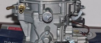
Carburetor VAZ 2107 - design
The design of the carburetor we are interested in is classic for the Ozone product line. In total, its design has more than 60 elements, which are arranged into several main functional units. These nodes include:
- dosing systems (in this version of “Ozone” there are two of them);
- pneumatic throttle valve drive;
- float chamber;
- an enrichment device called an econostat, which is located in one of the float chambers;
- crankcase gas removal mechanism;
- diaphragm accelerator pump equipped with a special sprayer (the pump is located in one of the chambers);
- autonomous idle mechanism with shut-off solenoid valve;
- float chamber transition systems;
- jets metering air and liquid fuel.
The throttle valves of the float chambers are opened as follows: the first chamber - from the passenger compartment using a control drive (the driver simply presses the pedal and the valve opens); the second chamber is driven by a pneumatic drive.
The carburetor jets are marked as follows: fuel: 112 (first chamber) and 150 (second); air: 190 and 150; accelerator pump: 40 and 40; pneumatic drive: 150 and 120. Idle jets are marked differently: fuel - 50 and 60, air - 170 and 70.
Carburetor Specifications
Pekar brand products, which are intended for use on VAZ power units, do not differ from similar DAAZ devices. Main parameters of carburetors of this type:
- Dosing systems: primary chamber diameter – 28 mm, secondary – 32 mm
- Diffuser geometry: chambers No. 1 – diameter 22 mm and No. 2 - 25 mm;
- Fuel jets of the main metering system, for the primary chamber - 1.12 mm, for the secondary - 1.50 mm.
- The dimensions of the air jets of this system for both parts of the device are 1.5 mm.
The main indicators of the unit for the carburetor transition system, which provide it with sufficiently high throttle response, are size and performance. The diameter of the hole intended to provide preparatory processes when connecting the secondary chamber of the device. By successively pressing the lever ten times, up to 7 ml of fuel is injected into the chamber. This allows you to achieve sharp acceleration of a VAZ car when using a Pekar brand carburetor.
Adjusting the DAAZ 1107010 carburetor - general requirements for the operation
The 2107 carburetor is adjusted according to the same principles as any other carburetor. The adjustment is carried out on the basis of standard calibration data, which contains all the parameters without which high-quality adjustment and tuning of the device is impossible. Experts advise performing these procedures at least once a year (some pros believe that adjustments and tuning should be carried out every six months if the car is used quite intensively).
Qualified carburetor maintenance consists of the following steps:
- thorough inspection of the device from the outside, cleaning and washing it;
- visual inspection of all units and components for wear;
- cleaning and washing the float, the idle system, the strainer (checking it for functionality, by the way, is required at least every 30 thousand kilometers of the “Seven”), the starting mechanism, and the jets.
After this, you can proceed directly to adjusting all of the above components.
Adjustment procedure
Adjustment is carried out only on a serviceable and serviced carburetor. It is highly desirable to have a device that can measure harmful CO emissions. Let's look at the procedure:
- We check the level in the float chamber. This is done using a template, which you can make yourself or purchase at a specialized store.
- We check the gaps of the contact group of the ignition distributor (look in the technical book of your car) and visually inspect the spark plugs. The latter must strictly correspond to the engine model according to the heat rating.
- We start the engine and let it warm up to operating temperature.
- We use a screwdriver to adjust the screw for the amount of combustible mixture. With its help, you should set the speed within 820-900 rpm. We control their number using a tachometer (built-in or separate).
- We tighten the fuel mixture quality screw. At the same time, it is important to monitor the amount of CO in the exhaust gases (a working engine at a temperature of 20 degrees Celsius produces 0.5-1.2% CO).
- Use the mixture quantity screw again and set the idle speed.
Features of servicing the strainer and float chamber
The filter is checked and serviced according to the following scheme: pump up fuel (manually); the float chamber is filled with fuel and the valve is monitored; then dismantle the filter (you need to slightly move the lid covering the filter from above); wash the mesh product in a solvent and dry it using a jet of compressed air. After these simple procedures, the filter will again be ready to perform its functions, protecting the vehicle from losses and power failures under load.
Be sure to clean the float chamber. This is done using a rubber bulb (after cleaning and washing, you need to dry the chamber with compressed air). Please note that under no circumstances should the bottom of the chamber be wiped with rags with a fluffy surface (it is better not to use rags at all), since after such treatment there is a high probability of clogging the carburetor jets with fiber particles that a person simply cannot see.
Do-it-yourself dismantling of the unit
To remove the DAAZ 2107 carburetor, auto mechanics recommend proceeding in the following sequence:
- The hood of the car is opened, the clamp on the warm air intake hose is loosened using a flat screwdriver, after which the hose is disconnected from the thermostat tube. The air intake hose is disconnected from the thermostat
- The air filter cover is removed manually. Under it there is a mounting plate, which is held on by four bolts. They are unscrewed with an 8-mm open-end wrench, after which the plate is easily removed. The mounting plate of the DAAZ 2107 carburetor is removed manually
- Now the air filter itself is removed from the VAZ 2107. The air filter from the VAZ 2107 is removed after removing the mounting plate
- Using the same 8 key, loosen the nut on the carburetor choke cable. Then the screw securing this cable is held with a flat screwdriver, the nut 8 is unscrewed completely and the cable is disconnected from the carburetor. The choke cable of the DAAZ 2107 carburetor is disconnected using a screwdriver
- The hose through which crankcase gases are discharged is removed from the fitting of the DAAZ 2107 carburetor manually. The hose for removing crankcase gases from the DAAZ 2107 carburetor is removed manually
- Next, the wires of the microswitches of the idle economizer control system (IAC) are manually removed. The wires of the economizer control system are disconnected from the DAAZ 2107 carburetor without much effort
- The vacuum ignition timing regulator has a fitting with a vacuum hose. This hose is also removed from the DAAZ 2107 carburetor manually. The hose of the vacuum ignition timing regulator is removed from the DAAZ 2107 carburetor by unscrewing the screws
- Now you need to find the hose for the solenoid valve. It is connected to the economizer through a fitting. This hose must also be removed. The solenoid valve control hose is manually removed from the DAAZ 2107 carburetor
- After disconnecting this hose, the return spring of the solenoid valve of the DAAZ 2107 carburetor is removed from the socket. The return spring of the solenoid valve of the DAAZ 2107 carburetor is manually removed from the socket
- Use a flathead screwdriver to loosen the clamps on the fuel hoses. These hoses are then removed. Fuel hoses from the DAAZ 2107 carburetor are removed manually after loosening the clamps
- Using a 14mm wrench, unscrew the four nuts that hold the carburetor to the manifold body. The DAAZ 2107 carburetor mounting nuts are unscrewed with a 14-mm open-end wrench
- The DAAZ 2107 carburetor is removed from its original place. After unscrewing the fasteners, the DAAZ 2107 carburetor is removed manually
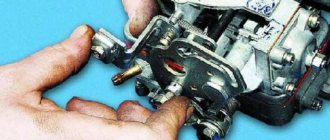
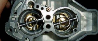
Adjusting the float mechanism
The operation is carried out in three stages. First, the float is checked to ensure its correct location in relation to the walls of the chamber and its lid. This procedure makes it possible to achieve “ideal” immersion of the float by eliminating the phenomena of deformation of the bracket on which it is mounted. Deformation can be eliminated simply by straightening the fastening element with your fingers.
Secondly, close the needle valve and begin to adjust the 2107 carburetor: put the lid in a vertical position, move the float to the side, and bend the bracket tongue (using a screwdriver). All these operations are performed in order to achieve a gap between the float and the cover at a level of 6–7 mm. Thirdly, open the valve, move the float to the side, and achieve a gap of 15 mm between the needle seat and the float.
As you can see, adjusting the float cannot be considered a very difficult task. Dealing with it is not so difficult, the main thing is to be very careful and careful and not try to do everything quickly.
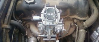
Equipment location and dismantling
The standard fuel mixer is installed on the exhaust manifold platform using four studs in the engine compartment. It is recommended to carry out prophylaxis in the removed state. The design contains many small parts and mechanisms that require cleaning and diagnostics. Of course, if the breakdown is obvious and insignificant, then there is no need to dismantle the equipment at all. The final decision is made by the repairman. After all, this directly proportionally affects the final cost of the work.
To remove the carburetor from its standard seat, you must:
- Unscrew the air filter cover on the right side of the engine, remove the cleaner itself and its housing part. Having previously unscrewed the four nuts to “8”. Some motorists independently modify the mechanism to accommodate long “10” bolts for ease of fixation;
- disconnect the crankcase exhaust pipes, vacuum hose, fuel supply pipe, return channel. Since there are gasoline residues in the pipes, you need to get a rag to remove the consequences of the leak.
Note to the driver: it is strictly forbidden to carry out repair work on a “hot” engine, as there is a high probability of ignition. Ignoring these recommendations leads to undesirable consequences. Woe - craftsmen often get burned.
When the body part of the “mixer” is completely freed from third-party mechanisms, it is necessary to release the fastening bolts of the top cover using a Phillips-head screwdriver. Just five;
This completes the dismantling of the upper half of the cover. To carry out a full diagnosis/repair, it is necessary to unscrew the second - lower part. The landing platform is mounted on four studs with nuts.
When removing the carburetor from its original place, you need to be extremely careful. The manifold outlet is open and a foreign object may get inside that should not be there. This can lead to the inoperability of the entire unit.