04/27/2021 6,081 GAZ
Author: Ivan Baranov
Every modern car is equipped with a generator device, which is used to power electrical equipment connected to the on-board network. And Gazelle cars are no exception. What is a GAZ 3110 402 engine generator, what elements does it consist of and what do you need to know about malfunctions? Read about it below.
[Hide]
Generator GAZ 3110
Cars of the Volga GAZ 31105 (ZMZ 406) family are equipped with generators of type 9422.3701, 3212.3771, 2502.3771.
AC power supplies, three-phase, with pre-installed rectifier and voltage regulator, right-hand rotation. The power source (hereinafter referred to as the PS) is driven by a V-shaped, poly-V belt from the crankshaft pulley.
If the IP fails, it can be replaced with a new one. The process of self-prevention is not at all complicated, but it requires experience in vehicle maintenance. Carrying out diagnostics in a non-professional manner does not guarantee the functionality of the equipment.
What generator is installed on the GAZ 3110
Unlike other modifications of generator sets, in the GAZ 3110 the stator is tightened with four screws around the perimeter. The rotor shaft rotates on bearings that contain lubricant.
The front and rear bearings are pressed onto the shaft; if they fail, they can be replaced with new ones by first dismantling the unit from its original location.
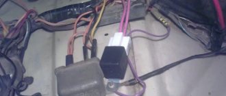
An excitation winding and rectifier diodes are installed on the rotor shaft. Power is supplied through two carbon brushes. In order to prevent the formation of interference, a capacitor is installed between the power outputs “+” and “-”.
The stator and rotor are cooled by air flow as the vehicle moves.
To reduce current consumption when the power unit is running, it is necessary to turn off the maximum number of current consumers: radio, radio, lighting, cooler, stove heater.
There are 6 coils mounted inside the generator set, the material is copper, the connection is star-shaped. The stator is a stationary structure, and the rotor rotates inside the stator. Magnetic brushes are pressed into the back of the rotor axis, and the excitation winding is wound and sealed.
After the key is turned in the ignition switch, the current from the battery creates a magnetic field, passing through the graphite brushes and copper winding. Alternating current is converted to direct current.
On the front side of the IP there are two power outputs with polarity “+” and “-”. Terminals with the appropriate polarity are connected to the battery.
To turn the generator set you will need a battery. After the battery has accumulated the spent amount of energy, the generator distributes the excess to other power sources. Thus, the size of the on-board network is maintained within an acceptable range.
Typical reasons for the failure of the power supply on the GAZ 3110
- loose fixation of the drive belt;
- contamination of contacts;
- damage to rectifiers;
- brush wear;
- brushes sticking;
- short circuit;
- power supply interruption;
- The regulator does not work;
- bearing wear;
- pulley wedge;
- The fan is damaged.
Signs of malfunction of the IP on GAZ 3110
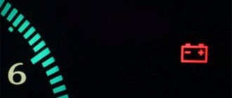
- The battery charge lamp is flashing;
- recharging the battery, the IP does not charge the battery;
- the light is not bright enough;
- quiet sound of the horn;
- extraneous noise when the IP is running.
Electrical circuit connection diagram for GAZ 3110 (402 engine)
The diagram is presented in the table below:
Typical malfunctions and methods for their elimination
What problems can occur in the operation of the generator:
- The diode bridge has failed. Experts recommend replacing the entire rectifier assembly. If necessary, you can change individual diode elements, but in this case they will need to be correctly pressed into the retainer; this procedure requires skills.
- Pulley damage or wear. Such a malfunction cannot be repaired; the device will have to be replaced.
- Worn brushes or commutator. If we are talking about wear and tear, then the repair procedure consists of replacing failed elements.
- Short circuit of the stator winding turns. In this case, you can try to rewind the winding, but this is a very painstaking operation and not everyone can cope with it. You will have to spend enough time, but it is not a fact that you will be able to achieve the desired result.
- Bearing failure. As a rule, such a problem is also associated with wear of the part, so faults of this kind are solved by replacement.
- Failure of the voltage regulator. The part also needs to be changed.
- Damage to electrical circuit wiring. Damaged sections of the circuit should be restored by replacing the wires.
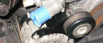
- Volga or Gazelle alternator belt wear. Wear may be indicated by signs of cracks and other damage to the structure of the strap. Such a malfunction cannot be repaired either; the strap should be changed (video author: Alexey Nadzhafo).
Disassembly instructions
Briefly about how to dismantle and disassemble the unit:
- First, the ignition is turned off, the hood is opened and the terminals from the battery are disconnected.
- Then you need to disconnect the power wires from the generator set.
- Using a tensioner, it is necessary to release the tension on the strap and remove it.
- Next, two screws are unscrewed that secure the assembly to the brackets, after which the device is removed.
- Now let's start the analysis. First, we dismantle the protective casing and remove the regulator relay, it is removed together with the brush assembly, you need to disconnect the wire from the relay.
- Next, you need to unscrew the four tightening bolts and dismantle the back cover with the stator mechanism.
- Now you need to disconnect the phase contacts of the winding from the rectifier device and dismantle the stator device. All components of the structure necessary for replacement and repair are removed, and assembly is carried out in the reverse order.
Replacement, repair and maintenance of the generator for GAZ 3110
Power supply location: engine compartment, to the right in the direction of travel of the vehicle.
Required materials and tools:
- open-end, spanner wrenches;
- knob, heads;
- torque wrench for precise clamping force;
- new drive belt as needed;
- plastic spatula for removing the belt;
- screwdrivers with a set of bits to change the brushes.
Step-by-step replacement instructions:
- We turn off the car engine.
- Open the hood.
- Loosen the terminals and remove them from the battery.
- Loosen the bolt that secures the bracket.
- We bring the generator set down.
- Remove the drive belt.
- We remove the IP from the engine compartment for further prevention.
- Upon completion of the diagnostic work, install the parts in reverse order.
After dismantling the IP, the master cleans it, performs an initial inspection, and determines possible breakdowns. The components are replaced with new ones, the terminals on the rotor are cleaned.
The part cannot be installed if cracks are found in the housing. Subsequent operation of the technical device is unsafe.
We check the integrity of the rotor winding with a multimeter. The diode bridge is also subject to prevention. Do not forget to check the integrity of the fuse, replace it with a new one as necessary, and observe the amperage.
Subject to the recommendations of specialists, subsequent maintenance of the power source after 30 - 40 thousand km.
To extend the life of electrical equipment, follow the technical inspection schedule. Purchase parts with original catalog numbers; a complete list of serial numbers is indicated in the table data.
Generator replacement
The entire generator unit on a car is changed in the following cases:
- if many parts in the device require replacement, and repairing the unit is not economically profitable, it is easier and cheaper to buy a new generator;
- you need to go on a flight urgently, and there is no time to do repairs;
- a new generator is installed, and the old one is repaired and put away as a reserve - it is a backup.
The difficulty of replacing the generator unit also depends on the engine model, but on any engine the work is done quite quickly, since it is still simple on all brands of Gazelle cars. The easiest way is to replace the generator on a car with a 402 engine; we carry out the work as follows;
- we place the car on a flat surface; in this case, you can easily do without a pit or a car lift;
- de-energize the electrical circuit - remove the terminal from the battery (preferably the mass one);
- unscrew the nut securing the power wire from the back of the generator (10 mm wrench);
- pull out the generator brush connector;
- unscrew the bolt of the tension bar of the alternator belt (12 mm wrench);
- first move the generator towards the engine with your hands, remove the generator belt;
- then we pull it away from the engine, unscrew the bolts and nuts (2 pcs.) – securing the generator unit to the brackets;
- dismantle the unit, install a new generator, attaching it to bolts and nuts;
- Do not tighten the fasteners all the way, press the generator housing against the engine, and put on the belt;
- Using a wrench or pry bar, we tension the belt and tighten the tension bolt;
After tensioning the belt, we secure the bolts and nuts to the end - they are now located under the generator, and getting to them is somewhat more difficult.
To fasten the generator securely, you need to install two nuts on the bolts, and be sure to lay it between the bolt and the nut along the engraver - on ZMZ-402 motors (as well as on UMZ-4216), vibration-proof fasteners tend to unscrew.
Characteristics of the gas generator 3110 402 and 406 engine: connection diagram and belt check
The Volga and Gazelle were equipped with the ZMZ 402 engine.
For this version of the car, a generator of type 16 KZATE or 19 ATE1 (Eltra) was used
These generators were completely interchangeable. They were identical in design and allowed the mutual use of parts for repairs.
For Volga engines, generators were equipped with a double-row pulley, for Gazelles - with a single-row pulley. For cars produced in the first half of the 90s, an alternating voltage output from the generator phase was used to operate the tachometer. In subsequent models, the tachometer received a signal from the ignition system, and the generator phase output was no longer needed; if the generator has one, it is simply not connected.
The generator has a traditional circuit. Winding, rotor, diode bridge, brush assembly. The voltage regulator type 13.3702 (131.3702) is separate and connected to the generator by wires.
Recommendations
Comments 9
406 motor.
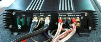
The generator heats up, the positive contact on it and the wire to the fuse. new generator at 100a. The wire is visually normal. I can't understand the reason. maybe someone had this W - “phase output” for example for connecting a tachometer, now no one uses it, but about the correct connection of D+, see Fig. 9 - amastercar.ru/articles/el...equipment_of_car_11.shtml HL - control light with a picture of the battery in tidy.
“B+ is charging, D+ is excitation, W is the output of one of the phase windings of the stator (it has alternating voltage). It can be used, for example, to connect a tachometer or hour meter on some special equipment. On AvtoVAZ products this terminal is not particularly relevant.”
information from the internet)
D+ - for tidy, voltage. W - to the tachometer.
So, D+ for tidy or excitement?
Excitation! on 3110 it goes through the tidy! and for one on the arrow...
The circuits of generators 9422 and 5102 are the same.
When the ignition is turned on, current from the battery flows through the ignition switch contacts, then through fuse 3 and through the light bulb in the instrument panel to point D of the generator. This point is the output of additional diodes. Next, the current goes to the input of the voltage regulator. The voltage acting on at this point opens the regulator transistor and the current passes through the brushes into the excitation winding and then through the open transistor to ground.
The generator is excited and when the rotor rotates, voltage appears at the generator output. The generator itself becomes a source, begins to charge the battery and power all devices. The current to the load comes from the generator.
Part of the generator current is diverted through an additional rectifier into the excitation winding, that is, the generator provides itself with excitation current.
The light on the instrument panel has two functions. Its resistance limits the excitation current from the battery to 100 mA. and shows whether the generator is working or not. When the ignition is turned on, it lights up because the initial excitation current flows through it - this is a message that the generator is ready for operation. When the generator starts, the light goes out - this is a signal that everything is in order, the generator is working.
If the light comes on while driving, “Attention, the generator has stopped working.” A voltmeter is connected parallel to the paw, which shows the voltage when the ignition is on; this is useful for monitoring the operation of the generator, battery and loads.
. Generator diode bridge
For a 90 ampere generator 3222.3771, a diode bridge with 8 diodes is used
The rectifier (diode bridge) consists of six (eight) diodes. Three additional small diodes are designed to rectify the excitation current. A circuit with additional diodes, in contrast to a simple circuit, eliminates accidental battery discharge if the engine does not start and the ignition is on.
For cars produced in the 90s, an alternating voltage output from the generator phase was used to operate the tachometer. In subsequent models, the tachometer received a signal from the ignition system, and the generator phase output was no longer needed; if the generator has one, it is simply not connected.
Generator circuit for a Gazelle with engine 402
The circuit differs in that it uses a voltage ammeter to monitor the operation of the generator.
When the ignition is turned on, current from the battery flows through the ignition switch contacts, from point 151, to the brush, then through the rotor winding to the external regulator (which is located away from the generator). A separate wire comes to the + terminal of the regulator from point 151, plus from this wire, opens the voltage regulator and the rotor current passes to ground. This current magnetizes the rotor. The engine starts, the generator rotor begins to rotate, and its magnetic field excites an EMF in the generator winding. Already at idle speed the generator begins to produce voltage. The battery becomes a consumer and charging begins, the excitation winding of the generator is powered through the same circuit, only now not from the battery, but from the generator output. When connecting external consumers, everything is powered by the generator.
GAZ 31 › Logbook › modification of the standard generator ZMZ-406
I decided to eliminate voltage drops in the on-board network.
Initially, the car had the original 75th gen. with a fastened remote three-position voltage regulator (RN). Replacing the gene with a new 120th. I didn't make the weather. After some deliberation, the decision was made to modernize the voltage regulation circuit. The presence of drawdowns is due to the fact that in the standard circuit the LV controls the voltage directly on the diode bridge of the gene, reacting poorly to the situation in the on-board network. Thus, the gene works at 40-50 percent of the given power. In general, I bring to the attention of the public two connection schemes with an external LV and a standard internal LV. I have been using the circuit with an external LV for a year, the voltage is stable at 14.1V when all regular consumers and seat heating are turned on. PS Roughly speaking, the gene anchor is an electromagnet with a voltage value on which the voltage produced by the gene is regulated... the actual connection between the launch vehicle and the on-board network, if we take the standard circuit, goes through thirty-three knees... and in this case it happens directly...
circuit with remote launch vehicle
scheme with standard launch vehicle
Generator 402 Connection Diagram
Having laid out a new set of wires in a free place, its orientation will immediately be noticeable: The longest and thinnest bundle is intended for the rear part; The shorter one is for the interior; The largest number of wires and connectors is for the engine compartment.
If there is not enough charge, or it is completely absent, there may be several reasons for such problems: the brushes in the brush assembly are worn out; there are breaks or short circuits in the armature winding; these same defects are present in the stator winding; The diode bridge is faulty. How to connect a generator.
Already at idle speed the generator begins to produce voltage. Let's put the removed generator on the table and turn it by the pulley; if you hear a rumble, then the bearings need to be changed. Replacing the regulator relay on a UAZ 469
Generator connection diagram for VAZ 2107
Namely, to correctly adjust the operation of the ignition system elements. The voltage should be 13.6 - 14 Volts; when the headlights and heater are turned on, it should not drop below 13.4 Volts.
After this procedure, I had to straighten the impeller a little. This device was sufficient for breaking and tightening the nut. How to connect a generator to ZMZ 402
Generator 2022.3771 for UAZ-3151x with ZMZ-402 engine
The easiest part in terms of connection is the rear part of the car, where you only need to secure the harness and connect the rear lights and the fuel level sensor in the gas tank.
Generator device
I repeat, on older models it is more correct to connect powerful loads directly to the generator.
The rear bearing is pressed onto the rotor shaft and is pressed by the rear cover through a plastic sleeve. The higher the speed, the greater the EMF, which means the voltage can rise to unacceptable values. I give the load: long range, heater, heated glass, I also turned on the emergency lights. The higher the speed, the greater the EMF, which means the voltage can rise to unacceptable values. The needle on your own voltmeter should be on the green scale.
Since the belt drive also ensures the rotation of the water pump, when the generator belt is too tight, noise appears from the bearings of the pump and the generator itself. A device that maintains voltage at the same level is called a voltage regulator. Generator 90A for UAZ - G287
Repair and troubleshooting
All mechanical problems are eliminated by replacing faulty components and parts (brushes, belt, bearings, etc.) with new or serviceable ones. Older generator models often require grinding of slip rings. Drive belts are replaced due to wear, maximum stretching or expiration of service life. Damaged rotor or stator windings are currently being replaced with new assembled ones. Although rewinding is common among auto repair services, it is becoming less and less common - it is expensive and impractical.
But all electrical problems with the generator need to be solved by checking both other elements of the circuit (in particular the battery), and directly its parts and output voltage. One of the common problems that car owners have to deal with is overcharging, or, conversely, low voltage of the generator. Checking and replacing the voltage regulator or diode bridge will help eliminate the first malfunction, but low voltage output will be a little more difficult to deal with. There may be several reasons why the generator produces low voltage:
- increased load on the on-board network by consumers;
- breakdown of one of the diodes on the diode bridge;
- failure of the voltage regulator;
- slipping of the poly V-belt (due to low tension)
- poor contact of the ground wire on the generator;
- short circuit;
- drained battery.
About classic UAZ SUVs and off-road vehicles
In subsequent models, the tachometer received a signal from the ignition system, and the generator phase output was no longer needed; if the generator has one, it is simply not connected.
The video above just shows the option of starting a car unprepared for winter. The generator rotor is driven by a V-belt from the engine crankshaft pulley. Similarly, the excitation winding receives power through the brush voltage generator.
But there were some bugs. Summary Although there is still time before winter, you should worry about the electrical components of your Gazelle in advance. That is, the battery begins to charge at lower speeds than in the standard version.
The starter turns hard, cannot start the engine and there is not enough battery for the second attempt. All this can be avoided if you know what exactly you need to do... Technical aspects of winter operation The most obvious and pressing issue after a cold night in the open air is starting the engine. I give the load: long range, heater, heated glass, I also turned on the emergency lights.
22.8. Electrical circuit diagram with ZMZ-402 engine
Installation kit: generator Thus, repairing a generator means replacing the diode bridge and replacing the bearings; in other cases, it is more profitable to exchange it for a reconditioned one. The reliability of the excitation circuit does not increase: the relay-regulator is still critical to a good “ground”.
Before removing the generator, let's check it again. So, ordinary power relays come to our aid.
The conclusion from here is this: the standard ZMZ ampere generator almost does not work at lower speeds. Calling an electrician he knew, he said two cherished words and everything fell into place - Put on the light bulb! Generator First you need to install a test battery.
Voltage regulator type The generator rotor is driven by a V-belt from the engine crankshaft pulley. Generator brushes Voltage regulator The generator must provide a constant voltage level to the network. By the way, the Gazelle Business wiring diagram is also not immune from such cases. Three-level generator voltage regulator. Three-level generator voltage regulator.
Electrical equipment GAZ 3110
As in any car, the GAZ 3110 electrical circuit contains automotive wiring with connectors, various relays and sensors, fuses, instruments, as well as energy sources and consumers. Energy sources are a generator and a battery; consumers include:
Starter design diagram for Gas 3110
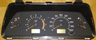
The Volga 3110 has an electronic speedometer. It should be noted that on the previous GAZ 31029 model the speedometer was equipped with a mechanical drive (cable). Also, unlike the 31029, the 3110 model now has a tachometer.
But the new device cannot immediately work on a GAZ car without problems, and therefore various problems arose with the speedometer and tachometer.
Electrical faults
Volgas have never been particularly reliable, and the electrical equipment on the car is far from ideal in quality. What are the main electrical faults found on the GAZ 3110:
Electrical diagram of the Volga 3110 windshield wiper
- On the 406th engine: the generator often “flies”, it is not always enough for 50 thousand km;
- the engine control unit is not very reliable;
- Domestic air flow sensors often fail;
- The phase sensors are not of high quality - because of it, fuel consumption increases.
- Switches overheat and fail;
Electrical wiring also often fails the owners of the 3110 - unreliable contacts can be in any connection. Fires in the engine compartment also happen due to wiring, although most often the car owners themselves are to blame for this. If there is dirt and oil under the hood, and gasoline is leaking from the fuel hoses, no car will withstand such careless treatment.
Checking the generator on cars with a ZMZ-402 engine
On cars with engines ZMZ-4025 and ZMZ-4026, generators 16.3701 or 191.3701 are installed, not equipped with a built-in voltage regulator.
These generators operate in conjunction with an external transistor voltage regulator type 13.3702-01 or 50.3702, which has electronic protection against short circuits in the generator excitation winding circuit.
It is more convenient to do the work together.
We start the engine, let it run for a few minutes, then, pressing the gas pedal, bring the crankshaft speed to 3000 rpm.
We turn on the consumers: high beam headlights; heater fan; wiper; emergency alarm.
In this mode, we measure the voltage at the terminals of the battery, which should be above 12 V.
If this is not the case, the generator windings are faulty (open or shorted), the voltage regulator with the brush assembly is faulty, the contact rings are oxidized or oiled, the brushes are worn out or stuck.
In order to verify that the voltage regulator is faulty, turn off all consumers except the side lights and measure the voltage at speeds of 1000...1200 rpm, which should be within 13.8...14.5 V.
1. To check the generator excitation circuit, disconnect the connecting block from the regulator.
2. Connect a voltmeter or test lamp to terminal “W” of the block and the body of the voltage regulator. Turn on the ignition
If there is no voltage (the lamp does not light), one of the following malfunctions is possible: failure of contact of the excitation winding with the slip rings; break of the excitation winding; “hanging” of brushes in the channels of the brush holder; burning, oxidation and severe wear of the rotor contact rings.
Removing and installing a generator on a Volga GAZ 31105 car
Tools:
1. Before removing the generator from the Volga GAZ 31105 car, disconnect the wire terminal from the negative terminal of the battery.
Disconnect the wiring harness block from the mass air flow sensor.
2. Loosen the two clamps and remove the air supply hoses along with the mass air flow sensor.
3. Remove the accessory drive belt.
4. On generator 2502.3771, disconnect the two wire blocks from terminals “D” and “W” of the generator.
5. On generators 9422.3771 and 3212.3771, disconnect the wire block from terminal “D” of the generator.
Further, the removal procedure is the same for all generators. 6. Remove the protective cover from the “B+” terminal of the generator.
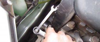
7. Use a 10mm wrench to unscrew the fastening nut.
8. Remove the wire tip from the “B+” terminal of the generator.
9. Using a 13mm socket, unscrew the nut of the bolt securing the generator to the bottom bracket, holding the bolt from turning with a 12mm wrench. We take out the bolt.
10. Using a 12mm socket, loosen the tightening bolt of the eye of the upper bracket of the generator.
11. Using a 13mm wrench, unscrew the nut of the bolt securing the generator to the upper bracket, holding the bolt from turning with a 12mm wrench (if necessary, the generator can be removed together with the bracket by unscrewing the two bolts securing the bracket to the engine with a 14mm wrench).
12. We take out the bolt (in order not to lose the bushing, we take it out of the bracket eye along with the bolt).
13. We remove the generator.
Note:
When installing a generator on a Volga GAZ 31105 car, it is more convenient to first secure it to the upper bracket. We insert the bolt into the eyes of the front cover and the generator bracket, and attach a nut to it. We fasten the generator to the lower bracket in the same way, tighten the nuts of the generator mounting bolts, and then the tightening bolt of the upper bracket eye. We put on the auxiliary drive belt and adjust its tension.
The article is missing:
Source