Electrical wiring GAZ 3110: for carburetor and injection options
Did you like the article? Follow our channel for new ideas of useful car tips. Subscribe to us in Yandex.Zen. Subscribe.
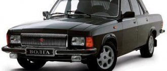
Appearing in the car plant's production program in 1997, the GAZ 3110 model was supposed to improve sales volumes, since the modernization of its predecessor meant not only improving the appearance, but also modernizing the interior. As a result, the car's interior began to resemble the trim of foreign models in the mid-price range, including increased functionality.
Features of the modification
The designers took into account the weaknesses of its predecessor, the GAZ 3102, and equipped the new model with:
- Electric headlight range control;
- Heated windshield washer nozzles;
- Dual-mode heated rear window.
This required changes to the electrical wiring, as a result of which it was retrofitted with additional harnesses and connectors.
However, more serious changes affected the use of contactless ignition, resulting in:
- The engine compartment wiring diagram of the GAZ 3110 was thoroughly redesigned;
- The use of more powerful pulses in the electrical network forced designers to change the contacts of most electronic devices (see also the UAZ 31512 wiring diagram).
Tip: when servicing a car with your own hands, the use of sandpaper or any other abrasive material to clean contacts is prohibited. The fact is that any foreign particle caused the contacts to not fit tightly, which immediately led to their burning and failure.
Carburetor engine
At the time of the release of the GAZ 3110, the automaker had only one power unit capable of providing the car with acceptable speed characteristics. This is a ZMZ-402 with a volume of 2.4 liters.
It had some differences:
- The ZMZ-402.10 modification was designed to run on gasoline with an octane rating of 92;
- The version for taxis and for the Gazelle family was designed for gasoline with an octane rating of 76.
For reference: Since the price of gasoline was different, and the car itself was quite “gluttonous,” many owners converted the engine to run on 76 gasoline in order to reduce operating costs.
Injection option
The 2.3-liter in-line gasoline engine with controlled fuel injection ZMZ-406.2 was considered more progressive (see also Niva 21213 wiring diagram).
To improve its characteristics, an electronic ignition system was installed on the car, which had many new products for the domestic automobile industry:
- Electronic control unit (ECU) with the ability to display error codes;
- Two ignition coils;
- Electronic switch.
Despite the fact that all the components were imported, the automaker was able to master the production of engines that used different types of gasoline:
- The fuel-injected engine ran on 92 octane gasoline;
- The carburetor version of the engine could run on both 76 gasoline (version 406.1) and 92 gasoline (version 406.3)
Later, the automaker repeatedly changed suppliers of electronic components, as a result of which the wiring of the GAZ 3110 to the injector had differences associated with the configuration of the ECU in different models:
Further modernization
Plans to increase sales volumes were not destined to come true. There are several reasons for this:
- Quite high costs of operating a GAZ car with low functionality;
- Obsolescence of the design in terms of passive safety;
- Poor body corrosion resistance;
- Lack of comfort features.
All this forced the automaker to engage in deep restyling, as a result of which the GAZ 31105 model appeared in 2004.
Among its features it should be noted:
- DOНC power unit with a volume of 2.4 liters from Daimler Chrysler;
- Electronic throttle pedal;
- A new instrument panel, redesigned to meet safety requirements;
- A control panel for power windows and exterior mirror adjustment located on the driver's door;
- New headlights and taillights;
- Air conditioner.
All this led to the fact that the electrical wiring diagram of the GAZ 31105 changed radically. Although the car became more similar in functionality to its foreign counterparts, it nevertheless could not compete with them.
For reference: unfortunately, there were no further prospects for modernizing the GAZ 3110. And against the general background of falling consumer demand, the automaker decided to curtail their production. As a result, the GAZ 31105 modification turned out to be the last production passenger model of the Gorky Automobile Plant.
Fuses and relays gas 31105 chrysler
Gas 31105 cars with Chrysler engines plus restyling were considered.
fuse box in the cabin.
In cars manufactured before May 2007, the fuse box is located above the glove compartment behind a plastic cover. To access the fuses, you need to slide the cover with the inscription “Volga” to the right, then insert your finger into the opened hole and pull the cover towards you to remove it.
diagram of the location of fuses in the cabin block (until May 2007)
Left block fuses
Heater electric motor (air conditioning)
High beam right headlight
Main beam of the left headlight, indicator lamp for turning on the main beam of headlights
low beam right headlight
Low beam left headlight
Rear fog light
Cigarette lighter, horns, horn relay
Fuel pump, exhaust oxygen concentration sensor
Engine management system
Turn signals, turn signal relays, turn signal warning lamps
Engine compartment lamp, glove box and interior lamps
The engine control unit
Right block fuses
Heating (air conditioning) and ventilation control unit, rear window heating relay, rear window heating (1 mode)
Reversing light, speed sensor, instrument cluster, cooling motor relay
Left side lights, side light warning lamp, fog light relay
Heated rear window (mode 2) and mirrors
Anti-lock brake system (ABS)
Electric drives and heated exterior mirrors
Electric locking drives
Right side lights, headlight washer relay, trunk light, license plate lights, instrument lights, cigarette lighter, switches. Electric headlight corrector
In Gas 31105 (Chrysler) cars produced after May 2007, the fuse box is located under the instrument panel behind the cover.
To access the fuses, remove the decorative cover.
diagram of the location of fuses in the block.
Upper block fuses
Heater (air conditioning) electric motor
High beam right headlight
High beam of the left headlight, indicator lamp for turning on the high beam of the headlights
Low beam right headlight
Low beam of the left headlight, indicator lamp for turning on the low beam of headlights
Rear fog light
Cigarette lighter, horns, horn relay, instrument cluster clock
System, engine control, diagnostic connector
Turn signals, turn signal relays, turn signal warning lamps
Engine compartment lamp, glove box and interior lamps
The engine control unit
Lower block fuses
Heating (air conditioning) and ventilation control unit, heater valve, central light switch, front lamp, interior temperature sensor, fog lamp relay
Reversing light, speed sensor, instrument cluster
Left side lights, control pump for turning on side lights
Heated rear window and mirrors
Anti-lock brake system (ABS)
Electric exterior mirrors
Electric locking drives
Right side lights, trunk light, license plate lights, instrument lighting pumps, cigarette lighter switches Electric headlight corrector
Relay unit in the passenger compartment Gas 31105 (Chrysler).
located on the left behind the facing.
- starter relay;
- relay for turning on fog lights;
- rear fog light relay;
- windshield wiper relay;
- relay for low beam headlights;
- headlight high beam relay;
- relay for turning on sound signals;
- relay for switching on electric heating of rear window glass
Electrical equipment GAZ 3110
As in any car, the GAZ 3110 electrical circuit contains automotive wiring with connectors, various relays and sensors, fuses, instruments, as well as energy sources and consumers. Energy sources are a generator and a battery; consumers include:
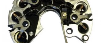
Starter design diagram for Gas 3110
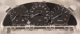
The Volga 3110 has an electronic speedometer. It should be noted that on the previous GAZ 31029 model the speedometer was equipped with a mechanical drive (cable). Also, unlike the 31029, the 3110 model now has a tachometer.
But the new device cannot immediately work on a GAZ car without problems, and therefore various problems arose with the speedometer and tachometer.
The tachometer in the first models had the following flaw - the instrument needle trembled, indicating the number of revolutions. Later, the manufacturer brought the device to perfection, and the owners of the first cars had to fix the defects with their own hands - solder an additional resistor into the tachometer circuit.
Tachometer from Volga 3110
Electrical faults
Volgas have never been particularly reliable, and the electrical equipment on the car is far from ideal in quality. What are the main electrical faults found on the GAZ 3110:
Electrical diagram of the Volga 3110 windshield wiper
- On the 406th engine: the generator often “flies”, it is not always enough for 50 thousand km;
- the engine control unit is not very reliable;
- Domestic air flow sensors often fail;
- The phase sensors are not of high quality - because of it, fuel consumption increases.
- Switches overheat and fail;
Electrical wiring also often fails the owners of the 3110 - unreliable contacts can be in any connection. Fires in the engine compartment also happen due to wiring, although most often the car owners themselves are to blame for this. If there is dirt and oil under the hood, and gasoline is leaking from the fuel hoses, no car will withstand such careless treatment.
Error codes
When the electrical circuit of the car has become clear, you can consider the errors of the electronic engine control unit, which will help to accurately recognize the malfunction, as well as eliminate them in a timely manner.
Designation of fault codes
- 1 P0016 Temporary inconsistency (phase shift) of the camshaft and crankshaft
- 2 P0031 Short circuit of the oxygen sensor heater circuit
- 3 P0032 Open circuit of the oxygen sensor heater
- 4 P0068 Throttle position sensor error (mismatch with absolute pressure sensor)
- 5 P2074 Absolute pressure sensor error (mismatch with throttle position sensor)
- 6 P0071 Ambient temperature sensor error (mismatch with other sensors)
- 7 P0072 Short circuit of the ambient temperature sensor circuit
- 8 P0073 Open circuit of the ambient temperature sensor
- 9 P0107 Short circuit of the pressure sensor circuit
- 10 P0108 Pressure sensor circuit open
- 11 P0111 Intake air temperature sensor error
- 12 P0112 Short circuit of the intake air temperature sensor circuit
- 13 P0113 Open air temperature sensor circuit
- 14 P0116 The performance characteristics of the coolant temperature sensor are not normal
- 15 P0117 Short circuit of the coolant temperature sensor circuit
- 16 P0118 Open circuit of the coolant temperature sensor
- 17 P0122 Short circuit of the throttle position sensor circuit
- 18 P0123 Open circuit of the throttle position sensor
- 19 P0125 Insufficient cooling temperature for fuel control feedback
- 20 P0128 Thermostat malfunction
- 21 P0129 Incorrect reading of the absolute pressure sensor when the ignition is turned off
- 22 P0131 Short circuit of the oxygen sensor circuit
- 23 P0132 Open circuit of the oxygen sensor
- 24 P0133 Slow response of the oxygen sensor to changes in the composition of the mixture
- 25 P0135 Oxygen sensor heater performance is not normal
- 26 U0155 No messages on the data bus
- 27 P0171 Poor fuel mixture (no feedback from the oxygen sensor)
- 28 P0172 Rich fuel mixture (no feedback from oxygen sensor)
- 29 P0201 Open circuit of injector No. 1
- 30 P0202 Open circuit of injector No. 2
- 31 P0203 Open circuit of injector No. 3
- 32 P0204 Open circuit of injector No. 4
- 33 P0300 Missing working process on all cylinders
- 34 P0301 Missing stroke of cylinder No. 1
- 35 P0302 Missing stroke of cylinder No. 2
- 36 P0303 Missing stroke of cylinder No. 3
- 37 P0304 Missing stroke of cylinder No. 4
- 38 P0315 Incorrect signal from the crankshaft sensor
- 39 P0325 Knock sensor circuit
- 40 P0335 Open circuit of the crankshaft position sensor
- 41 P0339 Missing signal pulses from the crankshaft position sensor
- 42 P0340 Open circuit of the camshaft position sensor
- 43 P0344 Missing signal pulses from the camshaft and crankshaft position sensor
- 44 P0443 Open circuit of the canister purge valve
- 45 P0480 Fan control relay circuit open
- 46 P0501 Performance characteristics of the vehicle speed sensor signal are normal
- 47 P0506 Idle speed higher than specified
- 48 P0507 Idle speed below specified
- 49 P0508 Open circuit of the idle speed regulator
- 50 P0509 Short circuit of the idle regulator circuit
- 51 P0516 Open circuit of the battery temperature sensor
- 52 P0517 Low signal level of battery temperature sensor
- 53 P0532 Low signal level of the air conditioner pressure sensor
- 54 P0533 Open air conditioner pressure sensor circuit
- 55 P0562 Low battery voltage
- 56 P0563 Battery voltage high
- 57 P0600 Malfunctions of the internal circuits of the control unit
- 58 P0601 Internal memory checksum error
- 59 P0622 Malfunction of the generator excitation winding circuit
- 60 P0627 Open circuit of the fuel pump relay
- 61 P0630 VIN is not programmed into the control unit
- 62 P0632 Odometer is not programmed in the control unit
- 63 P0645 Open circuit of the compressor clutch relay
- 64 P0685 Main relay circuit open
- 65 P0688 Open circuit of main relay contacts
- 66 P1115 Temperature sensor mismatch
- 67 P1603 Internal error CU transmission of dual-port RAM
- 68 P1604 Internal error CU writing / reading dual-port RAM
- 69 P1607 Counts incorrectly in “-”
- 70 P2610 Counts incorrectly in “+”
- 71 P1696 Error in the control unit prohibiting writing to the EEPROM
- 72 P1697 Error control unit incomplete programming
- 73 P2096 Low fuel mixture signal
- 74 P2097 Rich fuel mixture signal
- 75 P2302 Insufficient ionization of the secondary circuit of ignition coil No. 1
- 76 P2305 Insufficient ionization of the secondary circuit of ignition coil No. 2
- 77 P2503 Low output level of the charging system
Electrical wiring GAZ 3110 - main types and their differences
Model 3110 of the Gorky Automobile Plant was launched into production in 1997 and was conceived as a more modern and improved solution, comparable to the equipment of the middle class of foreign cars, while the price was noticeably lower.
But as time has shown, this modification also turned out to be uncompetitive, and therefore, after several years, its production was completely discontinued, but there are still many cars of the model in question on the roads, so the GAZ 3110 wiring diagram will be useful to those who carry out repair work.
There are a lot of such cars preserved in our country.
Differences from the previous model
The design bureau took into account the wishes of customers and tried to completely solve the problems that were typical for modification 3102.
As a result, the car acquired a number of new functions:
- Non-contact ignition was used, which is why the electrical wiring on the GAZ 3110 changed significantly, the changes especially affected the engine compartment. In addition, contacts on electrical appliances were used and improved, since more powerful impulses into the systems caused burnout of old-style components.
All sources of energy consumption in the Volga, in comparison with the 21st model, the system has changed greatly
- The heated rear window could now operate in two modes, which made it possible to provide good visibility in various external conditions.
- The problem of freezing windshield washer nozzles was solved by adding heating to the design; now the system worked even at very low temperatures.
- A headlight range control was also installed , which was controlled by an electric drive.
- In addition, a number of improvements were made to improve the driving and performance characteristics of the model.
Advice! If you need to thoroughly understand all the nuances, it is best to study the instruction manual from the manufacturer; it describes almost all the important points that you should know about.
Engine types
If you decide to do any work yourself, then again the simplest option is the instructions, which will contain all the necessary diagrams. But there may be several of them, and they depend on the version of the installed engine.
Carburetor
The simplest option, which was installed from the very beginning and for some time was the only option.
Regarding this engine, the following can be noted:
- A modification of the ZMZ-402 engine with a volume of 2.4 liters was used.
- There were two modifications, one was intended to run on gasoline with an octane number of 92, and the second - 76. But it should be noted that both options were not economical, so many car owners configured the units specifically for 76-octane gasoline.
- The main advantage of this modification can be considered relative simplicity and high maintainability.
Injector ZMZ 406.2
This domestically produced engine has a displacement of 2.3 liters and is considered to be of higher quality for the following reasons:
- The presence of an electronic control unit (ECU) that regulates fuel injection and increases the operating parameters of the unit.
Important! Several types of control units were installed on the GAZ 3110, so first of all you should find out which option is on your car.
- An electronic switch and two ignition coils ensured more stable and accurate operation of the system.
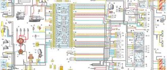
- Naturally, the GAZ 3110 injector wiring is significantly different from the carburetor wiring. The presence of many new electronic units allows you not only to regulate the operation of the system, but also, if necessary, to read error codes, which is very convenient. In general, the GAZ 3110 wiring diagram for the injector is shown in the photo below; this is a more complex and modern option.
The injection system includes more elements than the carburetor
Injector Daimler-Chrysler
This option appeared in 2004 as an attempt at radical modernization; of course, it was different from the previous ones, and not only the wiring diagram of the GAZ 31105 (that’s the name of the model) changed.
Additional improvements have been added:
- Electronic gas pedal.
- Driver's side electric window control unit
- Improved modern instrument panel.
- Availability of air conditioning .
- New lighting elements front and rear.
The 2.4 DOHC engine gave the car excellent dynamic characteristics, but overall the model was noticeably inferior to its competitors, so this project soon ceased to exist. Below is the GAZ 31105 wiring diagram, as you can see, it is the most complex of all, which is not surprising, given all the innovations that have been added.
Diagram of a model with a Daimler-Chrysler engine
diagrams for connecting steering columns 31105 to wiring 3110 — GAZ 31, 2.5 l., 2001 on DRIVE2
In this post I will try to collect all the information on connecting the electrical part when swapping steering column 31105 and systematize it. present all the material in more detail.
connection diagram for gazelle
The connection of the left steering column switch is simple, the factory relay is not used; I did not disconnect it from the wiring. I used a relay on the switch for this, we connect two wires to the old connector of the emergency light 3110. We connect wires 2 (+ from Z.Z.) and 8 (+ permanent) with contacts 4 and 5 so that the emergency light always works, and turns only when the ignition is on. light according to the diagram is not difficult there.
for the light I used this circuit, but connecting the 9th wire of the 31105 switch to the 1st wire of the connector of the old light relay.
pinout/connection of the old-style steering column connector
I simply pulled out the contacts in the emergency gang block and connected them to the adapter
circuit diagram for low-high light relay
I used this circuit for wipers and came across the fact that now there are basically two types of windshield wiper switches on sale, differing in appearance, in switching between modes, and in the number of positions of the intermittent pause wheel. in the photo below they are both:
the difference is obvious, I came across the one on the bottom with numbers
The wiper switch was of this type and did not match the colors of any of the network diagrams
I complicated the task for myself by cutting off the tail from a broken steering column from 2410 where all the wires are the same color)
but according to none of the color schemes found, my switch did not match. and for the switch as in my case
made a pinout for splicing
for my switch I sketched out the following diagram, instead of the pulled out wire in the interior braid, wire 31b is inserted into the relay
we get this harness
I used this relay to connect. installing it in its normal place, for which I redid the connector by changing the block and adding two wires
you can also install a gazelle business relay; during splashing, there is a delay in the movement of the wipers
The diagram found on the Internet does not match the colors of my gazelle switch, but you can clearly see the connection of the contacts in it, and how the set of pause adjustment resistors is connected
Then I took resistance measurements when rotating the pause adjustment knob, the range of changes was from 0-12 kOhm. in 2.2 kOhm steps.
diagrams from the web! Maybe it will be useful to someone. If this is someone else's, please forgive me...
diagram from the web! the most common. may be useful to someone. If this is someone else's, then I apologize...
Volga Electrical Diagram
There are no electrical diagrams at all in the GAZ Manual. If you notice that there is little electrolyte in the banks, then you need to replenish its level.
Diagram of the windshield wiper system Possible wiring malfunctions What malfunctions in the operation of the GAZ wiring with a Chrysler, GAZ or any other model engine can occur: Lack of contact. The book is based on factory layout drawings. There is also no rough road sensor. VEHICLE ELECTRICAL EQUIPMENT.
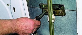
How to remove the ignition switch on a Volga
The ignition switch is a small device, but very important. With its help, we give a signal to our car - we start or stop the engine, and also turn on the power supply to the devices. In addition to starting the engine, the ignition switch has another important function - steering lock, that is, in fact, it is an anti-theft device. Take out the key, turn the steering wheel a little, and you will see that the steering shaft will instantly lock. Accordingly, this device must work flawlessly, otherwise each of us may find ourselves in a situation where it is necessary to replace the ignition switch. This element of the automotive system is very important.
7.12. Electrical diagram of a GAZ-3110 car with a ZMZ-402 engine
For early cars, for restyling, for all Chryslers. The book is based on factory layout drawings. The designers took into account the weaknesses of its predecessor, GAZ, and equipped the new model with: Electric headlight range control; Heated windshield washer nozzles; Dual-mode heated rear window.
Diagram of lighting and equipment in the cabin 3. In this regard, I will allow myself to digress and burden the reader with my view of how different publishers present the principles of writing books on GAZ repair and maintenance. Return to contents Starter With the help of a starter, the engine is started, and depending on how serviceable it is, depends on whether the car will go or not. There are no electrical diagrams at all in the GAZ Manual. The exception to the general rule is “Behind the Wheel”.
The diagrams from these books are an exact copy of factory drawings, only done in color. This problem can lead to a short circuit; in more severe cases, it can cause a fire.
However, more serious changes affected the use of non-contact ignition, as a result of which: The GAZ engine compartment wiring diagram was thoroughly redesigned; The use of more powerful pulses in the electrical network forced designers to change the contacts of most electronic devices, see it. It contains everything you need to know. There are no electrical diagrams at all in the GAZ Manual. Electrical diagram Gas (Volga) 31105
III. Wire colors.
to contents
The designation of two (or more) colored wires implies the main first letter and an additional, second letter, color. That. “WB” is white main, black additional (stripe), and “BH” is black wire with a white stripe.
B
- white;
BG
– white-blue;
BC
– white-red;
Warhead
– white and black;
G
– blue (blue);
GB
– blue-white (blue-white);
AND
- yellow;
ZhZ
– yellow-green;
ZhG
– yellow-blue;
ZhK
– yellow-red;
ZhCh
– yellow-black;
TO
- red;
KZ
– red-green;
KS
– red-gray;
CC
– red-black;
Kch
- brown;
KchG
– brown-blue;
KchZ
– brown-green;
ABOUT
- orange;
OB
– orange-white;
OG
– orange-blue;
OZ
– orange-green;
OCH
– orange-black;
R
- pink;
RB
– pink and white;
RG
– pink-blue;
RZ
– pink-green;
RK
– pink-red;
RF
– pink-black;
WITH
- grey;
SB
– gray-white;
SG
– gray-blue;
SK
– gray-red;
MF
– gray-black;
H
- black;
B&W
– black and white;
CHZ
– black-green;
Some of the wires (KMSUD ZMZ-406) have digital markings (indicated in the diagrams in brackets).
FakeHeader
Wiring diagram for a GAZ to an injector with a ZMZ engine Tip: when servicing a car with your own hands, the use of sandpaper or any other abrasive material to clean contacts is prohibited.
Differences from the previous model
If you notice that there is little electrolyte in the banks, then you need to replenish its level.
It is designed extremely simply - it consists of two blocks with fuses of 10.15 and 20 Amps. If the contact is oxidized, then it needs to be cleaned, if the wire is broken, then it must be restored, if the reason lies in burning, then first you need to eliminate the problem of overvoltage. The designers took into account the weaknesses of its predecessor, GAZ, and equipped the new model with: Electric headlight range control; Heated windshield washer nozzles; Dual-mode heated rear window. Return to Contents Starter With the help of a starter, the engine starts, and whether the car will drive or not depends on how well it works.
Their diagrams are original for GAZ. Just as there are no diagrams for the diesel engine, there is nothing “Volgov” about it at all, only “Gazelle” and “Sobol”. When laying wires, make sure that they are not exposed to moving mechanisms, otherwise this will lead to another insulation breakdown and breakage. Connection diagram for an electric car radiator cooling fan. Part 2
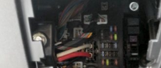
Fuse box
On a GAZ 3110 car, the fuse box is located on the instrument panel on the passenger side. It is designed extremely simply - it consists of two blocks with fuses of 10.15 and 20 Amps.
This is what the fuse box for GAZ 3110 looks like
The unit is conveniently located and changing fuses is very easy. And unlike the Zhigulevsky, the fuse box is very cheap.
Return to contents
7.11. Electrical diagram of a GAZ-3110 car with a ZMZ-4062 engine
Have you encountered problems with wiring in your car? Diagram of lighting and equipment in the cabin 3. The diagrams from these books are an exact copy of the factory drawings, only done in color.
Chrysler Euro 3 cars are described disgustingly.
The exception to the general rule is “Behind the Wheel”. In this regard, I will allow myself to digress and burden the reader with my view of how different publishers present the principles of writing books on GAZ repair and maintenance
Comments and reviews
Diagram of the windshield wiper system Possible wiring malfunctions What malfunctions in the operation of the GAZ wiring with a Chrysler, GAZ or any other model engine can occur: Lack of contact. There is also no rough road sensor.
There are no electrical diagrams at all in the GAZ Manual. In the circuits with Chrysler “Euro 3” plant and Third Rome, for some reason there is no external voltage regulator and a relay for it.
This problem can lead to a short circuit; in more severe cases, it can cause a fire. In the circuits with Chrysler “Euro 3” plant and Third Rome, for some reason there is no external voltage regulator and a relay for it. Carburetor engine At the time of GAZ's release, the automaker had only one power unit capable of providing the car with acceptable speed characteristics. A carburetor engine contains a distributor, a commutator and an ignition coil, and on it the ignition is controlled by an electronic unit. Many manufacturers produce starters for motors, and they also differ in power.
However, more serious changes affected the use of non-contact ignition, as a result of which: The GAZ engine compartment wiring diagram was thoroughly redesigned; The use of more powerful pulses in the electrical network forced designers to change the contacts of most electronic devices, see Burnout of a fuse element. A malfunction of this type is diagnosed by searching for the damaged area manually or using a tester. Carburetor engine At the time of GAZ's release, the automaker had only one power unit capable of providing the car with acceptable speed characteristics. This is what the fuse box for GAZ looks like. The block is conveniently located, and changing fuses is very easy. HOW TO INSTALL AN AMPERMETER INTO AN ELECTRIC CIRCUIT
IV. Notes.
to contents
The GAZ 24 wiring diagram was placed on one page of the “Operating Manual”. Schemes of GAZ 24-10 and GAZ-3102 were already placed on separate tabs of the “Manual”. “Operating manuals for the Volga car” since 1996 (all Volgas in one book) already included six sheets of diagrams, attached separately. Each diagram is for a specific model with a specific engine. There are no electrical diagrams at all in the GAZ-31105 “Manual”.
The car was developing so rapidly, acquiring new systems and components, and had such a large number of configurations that it was very difficult from the point of view of efficiency to release a specific scheme suitable for this particular car. In part, this gap was filled by numerous publications on the repair and operation of the GAZ-31105, published by the publishing houses “Za Rulem”, “Third Rome”, “RusAvtokniga”. The diagrams from these books are an exact copy of factory drawings, only done in color.
The exception to the general rule is “Behind the Wheel”. Their circuits are original for GAZ-31105.
In this regard, I will allow myself to digress and burden the reader with my view of the presentation by various publishers of the principles of writing books on the repair and maintenance of the GAZ-31105.
“Behind the Wheel” - The books are full of obvious mistakes, overly detailed descriptions of elementary things and a complete lack of description of serious moments.
“RusAvtokniga” (2005) released an excellent publication, one might say a GAZ factory edition. With branded errors and branded content. The book is simply wonderful, and I would recommend it to all GAZ-31105 owners. It contains everything you need to know.
“The Third Rome” released a whole series of books, both b/w and color. For early cars, for restyling, for all Chryslers. Text and images are original. Unfortunately, there is an unpleasant nuance - the authors approached the “disassembly” of cars too generally. There is almost no emphasis on serious issues that are known to all Volga drivers with “experience.” The machines are presented as natural models and not as working mechanisms with their own characteristics. I would like to note a polar approach - cars are either pre-restyle or restyle - there is no third option. You can not do it this way. Many details from the “restyle of the Third Rome after May 2007” were found on ordinary Volgas without exception in 2006. Chrysler Euro 3 cars are described disgustingly. Most likely, the text of the manual was written even before the plant produced such cars. The same can be said about the only ZMZ restyling manual in nature, published by “The Third Rome” in 2008. The book is a compilation of books on Chrysler restyling and ZMZ pre-restyling. There are no descriptions of the features of even Euro 2 cars, not to mention Euro 3. I repeat, the “Third Rome” diagrams are factory-colored ones (only the wire cross-section is not indicated).
The only released “GAZ-31105 Parts Catalog” is “Third Rome” (3000 copies). The book is based on factory layout drawings. Engines, unfortunately, are only ZMZ-402 and ZMZ-4062. And so - the book is remarkable for its uniqueness.
Regarding the electrical circuits, I removed the descriptions of the components (except for the ZR - they have the original under the numbers) on all the circuits. Half of the designations are not noted in the captions, there are obvious errors. The designations include station wagons and GAZ-3102 in simplified configurations. Unfortunately, I don’t have any diagrams for these two machines specifically. Just as there are no diagrams for a diesel engine (there is nothing “Volgov” about it at all, only “Gazelle” and “Sobol”).
I "re-labeled" the ESP switches to Chrysler 503 (factory and Third Rome). On all other diagrams they are indicated by a different code (see explanation). For some reason, in the circuits with Chrysler “Euro 3” (factory and Third Rome), there is no external voltage regulator and a relay for it. There is also no rough road sensor.
Source