Volga and Gazelle UAZ with engines ZMZ 406, ZMZ 405, ZMZ 409 were equipped with generators 9422.3701 produced by KZATE and 5102.3771 produced by ELTRA and their numerous clones.
The circuits of generators 9422 and 5102 are the same.
When the ignition is turned on, current from the battery flows through the ignition switch contacts, then through fuse 3 and through the light bulb in the instrument panel to point D of the generator. This point is the output of additional diodes. Next, the current goes to the input of the voltage regulator. The voltage acting on at this point opens the regulator transistor and the current passes through the brushes into the excitation winding and then through the open transistor to ground.
The generator is excited and when the rotor rotates, voltage appears at the generator output. The generator itself becomes a source, begins to charge the battery and power all devices. The current to the load comes from the generator.
Part of the generator current is diverted through an additional rectifier into the excitation winding, that is, the generator provides itself with excitation current.
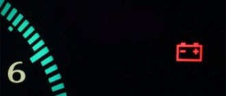
The light on the instrument panel has two functions. Its resistance limits the excitation current from the battery to 100 mA. and shows whether the generator is working or not. When the ignition is turned on, it lights up because the initial excitation current flows through it - this is a message that the generator is ready for operation. When the generator starts, the light goes out - this is a signal that everything is in order, the generator is working.
If the light comes on while driving, “Attention, the generator has stopped working.” A voltmeter is connected parallel to the paw, which shows the voltage when the ignition is on; this is useful for monitoring the operation of the generator, battery and loads.
. Generator diode bridge
For a 90 ampere generator 3222.3771, a diode bridge with 8 diodes is used
The rectifier (diode bridge) consists of six (eight) diodes. Three additional small diodes are designed to rectify the excitation current. A circuit with additional diodes, in contrast to a simple circuit, eliminates accidental battery discharge if the engine does not start and the ignition is on.
For cars produced in the 90s, an alternating voltage output from the generator phase was used to operate the tachometer. In subsequent models, the tachometer received a signal from the ignition system, and the generator phase output was no longer needed; if the generator has one, it is simply not connected.
The diode bridge for connecting the tachometer has an additional terminal. It does not interfere with installing a diode bridge on any generator of this series. Therefore, if they offer a diode bridge with an additional terminal, feel free to buy it.
Voltage regulator
The generator must provide a constant voltage level in the network. The higher the speed, the greater the EMF, which means the voltage can rise to unacceptable values. In addition, turning on devices greatly increases the load current, and the higher the current, the lower the voltage. Therefore, in all car generators the voltage is maintained at the same level. A device that maintains voltage at the same level is called a voltage regulator. The voltage regulator is included in the field winding circuit; it turns the field current on and off.
What should the voltage be? All electrical equipment is designed for a battery voltage of 12 Volts. To charge the battery, the generator voltage must be maintained approximately 2 Volts higher, so the operating voltage of the generator should be 14.2 – 13.8 Volts. If the voltage is higher, this will lead to the battery boiling out and shortening its service life, light bulbs and other devices will begin to burn out. If the voltage is lower, the battery will be undercharged, resulting in unexpected starter failures and shortened battery life.
If the generator is faulty
When starting the engine, the light on the instrument panel does not go out. The voltmeter confirms that the voltage remains at the same level that the battery provided. Charging does not work and driving is risky; after two hours the engine will stall and you can end up in the most inconvenient place. We need to go to where the generator will be repaired.
Broken or loose belt Poor contact on the power terminal Broken voltage regulator Complete wear of the brushes Complete wear of the slip rings on the rotor Broken rotor winding Burnt out generator winding Break or burnt out diode bridge
The voltage may, on the contrary, be higher than expected, this will be shown by the voltmeter, the arrow will go to the right.
The battery will overcharge and boil away, the light bulbs will start to burn out. We urgently need to change the voltage regulator.
A strong rumble from the generator indicates complete wear of the bearings; it is necessary to urgently change the bearings, otherwise the generator will jam
The performance of the generator device is primarily reflected in the operation of all electrical equipment in the car. This unit consists of many parts, so even the breakdown of one part can cause the entire unit to fail. How to properly maintain a Gazelle generator, what you need to know about diagnostics and how to change brushes correctly? We will talk about this below.
Generator circuit for Volga and Gazelle with engine 402
For Volga engines, generators were equipped with a double-row pulley, for Gazelles - with a single-row pulley.
For cars produced in the first half of the 90s, an alternating voltage output from the generator phase was used to operate the tachometer.
In subsequent models, the tachometer received a signal from the ignition system, and the generator phase output was no longer needed; if the generator has one, it is simply not connected.
The generator has a traditional circuit. Winding, rotor, diode bridge, brush assembly. The voltage regulator type 13.3702 (131.3702) is separate and connected to the generator by wires.
Generator diagram for Volga with engine 402
Generator circuit for a Gazelle with engine 402
The circuit differs in that it uses a voltage ammeter to monitor the operation of the generator.
When the ignition is turned on, current from the battery flows through the ignition switch contacts, from point 151, to the brush, then through the rotor winding to the external regulator (which is located away from the generator). A separate wire comes to the + terminal of the regulator from point 151, plus from this wire, opens the voltage regulator and the rotor current passes to ground. This current magnetizes the rotor.
The engine starts, the generator rotor begins to rotate, and its magnetic field excites an EMF in the generator winding. Already at idle speed the generator begins to produce voltage. The battery becomes a consumer and charging begins, the excitation winding of the generator is powered through the same circuit, only now not from the battery, but from the generator output.
When connecting external consumers, everything is powered by the generator.
- Operating principle of the generator
- The rectifier (diode bridge) consists of six diodes that conduct the winding current in only one direction, this is how rectification occurs.
A magnetic field is created by an electric current. To do this, a winding is inserted inside the rotor, which is called the field winding. Current is supplied to the field winding through brushes pressed against the rotor rings.
Voltage regulator
The generator must provide a constant voltage level in the network. The higher the speed, the greater the EMF, which means the voltage can rise to unacceptable values. Therefore, all automobile generators are designed to maintain voltage at a given level when the engine speed changes.
In addition, when the devices are turned on, the load current increases and the higher the current, the lower the voltage becomes. A device that maintains voltage at the same level is called a voltage regulator. The voltage regulator is included in the field winding circuit; it turns the field current on and off.
What should the voltage be?
All electrical equipment is designed for a battery voltage of 12 Volts. To charge the battery, the generator voltage must be maintained approximately 2 Volts higher, so the operating voltage of the generator is maintained at 14.2 – 13.8 Volts.
If the voltage is higher, this will lead to the battery boiling out and shortening its service life, light bulbs and other devices will begin to burn out. If the voltage is lower, the battery will be undercharged, resulting in unexpected starter failures and shortened battery life.
The voltage at a given level is maintained by the voltage regulator.
- If the generator is faulty, the battery is discharged or poorly charged.
- This makes the following cases possible:
- The starter turns hard, but still starts.
- The starter turns hard, cannot start the engine and there is not enough battery for the second attempt.
- In the morning, the starter turns slowly and has difficulty starting the engine.
- The car will sit and you won’t be able to start it again.
- Pusher starts only
- Everything went dark and there was complete silence.
- The lights are dim and the signal is weak
- If the voltage rises above 15 Volts, this is already an overcharge
- The battery becomes wet and smells of acid
- Typically, overcharging occurs if the voltage regulator is broken; on Volga and Gazelle this is an external device and is easy to replace.
- What to do if the voltage drops and there is a suspicion that the generator is not working.
To understand what's going on you need to start the car. For example, install a test battery, or push start it.
The problem could be: the starter, the battery, the wiring or the generator. First you need to install a test battery. If it starts normally, then the starter and wiring are normal. Let's check the generator. The needle on your own voltmeter should be on the green scale. You need to check the voltage on the battery with a voltmeter.
The voltage should be 13.6 - 14 Volts; when the headlights and heater are turned on, it should not drop below 13.4 Volts. If so, then the generator is working. If the voltage is lower, then charging is weak or absent. First you need to make sure that the belt is tensioned well. Then measure the voltage at the generator output, it should be 13.6 - 14 Volts.
If it is lower on the battery, then the 60 A fuse is broken, or the fuse block contacts are rusty.
This is a common problem on old Gazelles. The charging current goes from the generator plus to the battery plus through a 60A fuse. This place quickly rusts and a whole volt or one and a half drops at the fuse contacts. It is better to install a new power fuse block.
If the voltage at the generator output is close to 12 Volts, then the generator does not work, there is no charging and the battery runs out.
Let's change the voltage regulator and install a test one. If the generator starts working and normal voltage appears on the battery, then everything is clear, you just need to change the voltage regulator. We buy regulator 13.3702 or its equivalent. If replacing the regulator does not help, then the problem is in the generator itself or in the wiring.
If the generator does not work with the test regulator, then first we will check whether the positive is coming to the generator brushes and to the voltage regulator. You can check with a voltmeter or test light.
You need to remove the connector from the generator brushes and from the voltage regulator. Measure the voltage at the removed connectors relative to ground. There should be a positive at one point on each connector.
If this plus is not present, then there is a break somewhere from the ignition switch to the connectors.
Before removing the generator, let's check it again. You need to take two wires with the “mother”, put them on the brush terminals instead of the connector, one (any) wire to the positive of the battery, the other to the negative and start the engine.
The voltage at the generator output will jump to 16 volts or more, the generator is running, turn off the engine and think further. If voltage does not appear, then the generator is definitely not working and will have to be removed.
- Let's put the removed generator on the table and turn it by the pulley; if you hear a rumble, then the bearings need to be changed.
- If the generator has a long mileage, then the bearings must be changed in any case.
- Let's analyze the generator:
If the generator is flooded, it is covered in oil and dirt. burnt or loose power terminal, burnt winding, burnt or rusty winding ends, worn copper rings on the rotor, then it is better to immediately exchange the generator for a reconditioned one.
If everything looks normal, the generator is dry and clean, then the diode bridge is faulty, or the stator or rotor winding is broken.
We check the diode bridge with any digital (or pointer) tester. There are six diodes in total. We measure the conductivity of each in one direction and then in the other direction.
If we check the resistance with a dial gauge, then in one connection the needle deviates strongly, and when connected in the opposite direction it deviates weakly, or the diode does not deviate.
If it deviates with one and the other connection or does not deviate at all, the diode is faulty and the diode bridge must be replaced.
The stator winding must be checked for ground fault. The resistance between any pin and ground (iron) must be very high (should not ring through)
We check the integrity of the winding. The resistance between the three terminals of the winding should be very small (everything should be connected).
If there is a breakdown or break, then the winding will have to be replaced (it’s easier to replace the generator)
Check the rotor winding. The resistance between the copper rotor rings should be 2.5-3 Ohms. If there is a break in the winding, or a breakdown to ground, the rotor must be replaced. When you try to install a similar rotor, it may turn out that it will not fit. It's easier to replace the generator.
Thus, repairing a generator means replacing the diode bridge and replacing the bearings; in other cases, it is more profitable to exchange it for a reconditioned one.
In some cases, the bearings are so rusty that they cannot be removed; this is also a reason to replace the generator with a rebuilt one.
Source: https://genrem.ucoz.ru/publ/skhema_generatorov/skhema_generatora_na_volgu_i_gazel_s_dvigatelem_402/13-1-0-134
Video “Gazelle electrical repair”
Very often, Gazelle owners, when replacing power units from carburetor versions to injection ones, are faced with the need to replace the electrical wiring in the car, since there are serious differences in the electrical circuit.
However, a complete replacement is not always justified, since the repair does not affect other electrical devices except the ignition and fuel injection systems.
Accordingly, when planning to replace the engine on a Gazelle, owners give preference to a more modern injection engine, for example ZMZ-4061 or ZMZ-4063.
As a rule, Gazelle cars produced before 2001 and having carburetor versions of power units require major repairs.
At that time, a 402 engine was often installed, and the Gazelle wiring diagram for the 406 engine, which appeared in the production program of the car plant in 1998, had its own design features that were not compatible with different types of engines.
What generator is installed on the GAZ 3110
Unlike other modifications of generator sets, in the GAZ 3110 the stator is tightened with four screws around the perimeter. The rotor shaft rotates on bearings that contain lubricant.
The front and rear bearings are pressed onto the shaft; if they fail, they can be replaced with new ones by first dismantling the unit from its original location.
An excitation winding and rectifier diodes are installed on the rotor shaft. Power is supplied through two carbon brushes. In order to prevent the formation of interference, a capacitor is installed between the power outputs “+” and “-”.
The stator and rotor are cooled by air flow as the vehicle moves.
| Specifications | 9422.3701 | 3212.3771 | 2502.3771 |
| Limit current strength at a voltage of 13.5 V and speeds above 5500 rpm | 57 | 77 | 82 |
| Adjustable voltage range | 13,5-14,4 | 13,5-14,4 | 13,3-14,6 |
| Gear ratio | 01.01.1970 | 01.01.1970 | 01.01.1970 |
| Capacitor capacity | 2,3±15% | 2,3±15% | 2,1±15% |
To reduce current consumption when the power unit is running, it is necessary to turn off the maximum number of current consumers: radio, radio, lighting, cooler, stove heater.
There are 6 coils mounted inside the generator set, the material is copper, the connection is star-shaped. The stator is a stationary structure, and the rotor rotates inside the stator. Magnetic brushes are pressed into the back of the rotor axis, and the excitation winding is wound and sealed.
After the key is turned in the ignition switch, the current from the battery creates a magnetic field, passing through the graphite brushes and copper winding. Alternating current is converted to direct current.
On the front side of the IP there are two power outputs with polarity “+” and “-”. Terminals with the appropriate polarity are connected to the battery.
To turn the generator set you will need a battery. After the battery has accumulated the spent amount of energy, the generator distributes the excess to other power sources. Thus, the size of the on-board network is maintained within an acceptable range.
Typical reasons for the failure of the power supply on the GAZ 3110
- loose fixation of the drive belt;
- contamination of contacts;
- damage to rectifiers;
- brush wear;
- brushes sticking;
- short circuit;
- power supply interruption;
- The regulator does not work;
- bearing wear;
- pulley wedge;
- The fan is damaged.
Signs of malfunction of the IP on GAZ 3110
- The battery charge lamp is flashing;
- recharging the battery, the IP does not charge the battery;
- the light is not bright enough;
- quiet sound of the horn;
- extraneous noise when the IP is running.
Electrical circuit connection diagram for GAZ 3110 (402 engine)
The diagram is presented in the table below:
Replacing bearings
If the bearings in the generator wear out, noise (hum) appears in the generator unit. It is possible to drive with such noise for a while, but it is not advisable, and you cannot delay repairs for a long time - the bearings can jam and burn out. Bearings are always replaced on a removed generator, and in order to replace it, the generator assembly must be disassembled. You can do this kind of work yourself, but keep in mind that the bearings are pressed in and will require a special puller to dismantle them. The rear bearing is rigidly pressed onto the rotor shaft, and it is practically impossible to do without a puller.
In some cases, the bearing in the front housing cover boils tightly, and in this case it is easier to replace it together with the cover.
Description of the generator
The ZMZ 406 generator is an electrical unit that provides stable voltage to the on-board network, as well as charging the battery during engine operation. The part is not difficult to repair and maintain. It ensures full functionality of vehicle electrical circuits. It is mainly installed on cars produced by the Gorky Automobile Plant (GAZ-31105, Gazelle, Volga). There is also an option for installation on old GAZ-24 and 31 vehicles.
The generator rotates to the right using a V-belt, which is driven by the rotation of the crankshaft. The latter is connected to the generator shaft by pulleys. The rotation speed is 1400 rpm. The maximum speed mode is 5000 rpm.
The output current rating is 14 volts and the power is 70 A. The field coil resistance ranges from 2.3 to 2.7 ohms. It is worth noting that the ZMZ 405-406 generator is the same parts and can be interchangeable. However, the manufacturer recommends installing the one that came from the manufacturer.
Installing a dynamo on the engine
Installation on the engine is carried out in compliance with a certain technological process.
First, unscrew the fastening nuts of the generator brackets to the crankcase. Next, install the dynamo and secure the front mounting bolt. Then we move the front bracket and achieve alignment of the crankshaft ratchet with the drive flywheel of the part and the pump drive. By moving the bracket, we achieve elimination of the gap between the generator loop.
Install the rear mounting bolt and firmly tighten the mounting nuts of the brackets to the engine crankcase. Next, we put the drive belt on the pulleys and tighten it using a tension bracket. We carry out a control check of the tightness of all threaded connections. We connect the part to the car's electrical network and put the terminals on the battery.
Therefore, solving such an issue is not particularly difficult, and besides, the process itself takes a small amount of time. You can save a lot on auto mechanic services.
Checking and repairing the generator on GAZ 3110 vehicles with 402 and 406 engines
Every modern car is equipped with a generator device, which is used to power electrical equipment connected to the on-board network. And Gazelle cars are no exception. What is a GAZ 3110 402 engine generator, what elements does it consist of and what do you need to know about malfunctions? Read about it below.
What elements does the engine generator unit 406 consist of, what is its connection diagram and what is the principle of operation? First, let's look at the description of the mechanism.
Design and principle of operation
The generator unit in Gazelle is a three-phase synchronous electric motor with electromagnetic excitation, as well as a built-in diode rectifier.
The rotor mechanism is driven into rotation from the crankshaft pulley of the power unit via a V-belt. The stator device, as well as the mechanism cover, are tightened with four bolts.
The shaft of the rotor mechanism rotates in bearings, which are located in the covers. By the way, bearing devices are lubricated for their entire service life.
The rear bearing is installed in the shaft of the rotor mechanism; it is pressed using the rear cover through a plastic sleeve. The front bearing element is located on the inside of the front cover. It is secured with a washer and four bolts.
The stator mechanism contains two three-phase windings that are connected to each other in parallel. A diode bridge or rectifier includes six diode elements that are mounted in two steel or aluminum plates. The plates themselves are combined into a rectifier unit, which is fixed inside the rear cover of the unit.
The mechanism is equipped with excitation windings, which are installed on the rotor mechanism. Their leads are soldered to two copper slip rings, which, by the way, are located on the mechanism shaft.
Power to the windings is provided by two carbon brushes connected to them and located in the brush holder.
Under the expansion tank, on the mudguard in the area of the right side member, there is a voltage regulator for the ZMZ Chrysler engine.
Why Chrysler? Because the first gazelle engines were equipped with these motors. The regulator operates in conjunction with the generator set and if this element fails, it must be replaced.
Also, the connection circuit involves the use of a capacitor device. This element is designed to protect the Gazelle's electrical equipment from possible impulses in the ignition system.
The capacitor also serves the function of reducing radio interference.
Cooling of the rectifier unit, as well as the windings of the mechanism, is carried out through the air flow entering through the holes in the centrifugal fan covers.
Device components
The node consists of the following elements:
- the housing in which the entire structure is enclosed;
- stator mechanism;
- rotary device or anchor;
- pulley and impeller;
- rectifier block or diode bridge;
- two bearing devices on which the rotor rotates;
- brush mechanism;
- voltage regulator.
Photo gallery “Connection diagrams”
How to check the generator?
The procedure for diagnosing a unit without dismantling is as follows:
- First you need to start the engine and let it warm up. Increase engine speed to 3 thousand per minute.
- Activate the optics - high beams, rear window heating system, stove, radio, light alarm and turn on the wipers. This is done in order to ensure operating conditions as close as possible to real ones.
- Next, using a voltmeter or multimeter, measure the voltage value at the battery terminals; this parameter should be at least 12 volts. If the obtained value is not the same, then this indicates that a problem has occurred in the operation of the windings - a short circuit or break. Or the fault lies in the voltage regulator or brushes. The problem may also lie in the oxidation of the winding rings.
Source: https://avtozam.com/gaz/3110-generator/
The Importance of Schemas
You can understand the fundamental importance of the Gazelle 405 electrical circuit simply based on how often this car has to be repaired. After all, as a rule, it is bought not for personal needs, but as a commercial machine. This means that he travels every day. You also need to make allowances for the conditions in which Gazelles drive, and how they are usually used:
- Exposure to natural conditions (poor wire insulation, short circuits).
- Poor build quality (cheap and bad wires that do not last long).
- Bad fuel, which has a detrimental effect on the electrical components of ignition and injection.
And only by using the electrical diagram can you figure out where which device is located and which wires are suitable for it.
If you try to replace something in the system yourself, without looking at the diagram, you can simply mix up the wires and do something to the car that you will then have to change all the wiring in the car.
Today, Gazelle cars are used in many sectors of modern business. To ensure the operability of the vehicle, it is necessary to pay attention not only to the performance of the main components and assemblies, but also to the electrical circuit of the Gazelle car. From this material you will learn everything you need to know about the operation of wiring and its malfunctions.
How to check the generator?
The procedure for diagnosing a unit without dismantling is as follows:
- First you need to start the engine and let it warm up. Increase engine speed to 3 thousand per minute.
- Activate the optics - high beams, rear window heating system, stove, radio, light alarm and turn on the wipers. This is done in order to ensure operating conditions as close as possible to real ones.
- Next, using a voltmeter or multimeter, measure the voltage value at the battery terminals; this parameter should be at least 12 volts. If the obtained value is not the same, then this indicates that a problem has occurred in the operation of the windings - a short circuit or break. Or the fault lies in the voltage regulator or brushes. The problem may also lie in the oxidation of the winding rings.
- So that you can verify that the control device is working, turn off all electrical equipment except optics; in particular, you will need side lighting. At engine speeds of 1000-1200 per minute, it is necessary to check the voltage, it should be about 13.5-14.2 volts.
Diagnostics of the functionality of the voltage regulator can be done by connecting a test light between the brushes. Of course, before this the relay must be dismantled. You need to connect 12 volts to contact D1, and minus to the ground contact. The light bulb should light up, and if the voltage level increases to 13.5-14.2 volts, the light source should go out. If the light is on and does not go out, the problem lies in the relay, it needs to be changed (the author of the video is Vyacheslav Lyakhov).
Causes of failure
If you are the owner of a Gazelle car, then the electrical circuit diagram will be useful to you in any case. At a minimum, so that, if necessary, it is possible to detect certain breakdowns caused by the use of low-quality fuel.
The reason for the inoperability of electrical appliances can be extreme climatic conditions:
- Difficult climatic conditions include severe cold. When frost sets in, the load on the electrical circuit of the vehicle increases, and the type of engine - carburetor or injector - does not matter here. The load on electrical equipment is especially noticeable during the morning start of the engine.
- Regardless of the time of year and type of internal combustion engine, every driver may encounter interruptions in the functioning of the injection system. When using low-quality gasoline or diesel, malfunctions in the ignition system of the combustible mixture may occur. To prevent such problems, it is necessary to use high-quality fuel.
- A Gazelle car owner may encounter other types of breakdowns and malfunctions. This may include short circuits, detachment of contacts on devices, or corrosion. All these shortcomings are caused by poor build quality or improper car repairs.
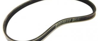
Belt for ZMZ 406 for generator: sizes and manufacturers
The size of the alternator belt depends on the presence of additional equipment installed on the power unit. If the vehicle is equipped with power steering, the length of the V-belt is 1370 mm. If the car does not have power steering, then 1220 mm will do.
The original belt for the ZMZ 406 generator has catalog number 406-1308020, 6PK1370 (for cars with power steering) or 6PK1220 (for engines without power steering). Its average cost is about 1000 rubles, depending on the place of purchase it can vary within 15%. In addition, many car enthusiasts recommend analogues that are suitable for installation:
- Luzar LB 0306 is another domestic option.
- Finwhale BP675 is a well-known German manufacturer of spare parts.
- Bosch 1 987 948 391 – German quality.
All presented analogues are suitable for installation on the ZMZ 406 generator instead of the original. As for quality, they are in no way inferior; they take care of their resources completely.
Rearranging the engine wiring
The Gorky Automobile Plant prudently divided the wiring bundles into front, rear and engine compartment. Therefore, when changing the power unit to another type of engine (for example, a ZMZ 406 carburetor to a ZMZ 405 injector), it is not necessary to change all the wiring, it is enough to just change the engine compartment wires.
It is also easy to rearrange the engine compartment wiring harness in case of replacing the 3M3 402 internal combustion engine with a ZM3 406 carburetor or ZMZ 405 injector.
Replacing a Cummins engine with a ZMZ 405
Unfortunately, cases of premature failure of the vaunted Cummins engine in the Gazelle Business are not uncommon, and car owners, having considered the costs of restoring the diesel engine, decide to install the proven and cheaper ZMZ 405 engine. Rearranging the engine requires changes to the electrical circuit. What is needed to connect power to the motor? It's simple, you will need it for ZMZ 405:
- Engine compartment wiring harness;
- Electric fuel pump;
- The engine control unit.
Analogues, originals, price, articles
| See all advertisements in the archive |
| Catalog item | Serial number | Price | |
| A2110-80A (original) | BOSCH (9501.3801) (original) | From 3000 – 3200 | |
| 9501.3801 | FINWHALE 687-04 | 62022 / 180545 | From 3000 – 3200 |
| 9568.3749 | 922.3801 | SKL622RS | From 3000 – 3200 |
| 3701010 (HORT) | 3701024 | Contitech | From 3000 – 3200 |
| 3701971 | 3701953 | Electro 3701747 | From 3000 – 3200 |
| *prices are as of August 2021 |
GAZ 31 (3110 - 406 engine) › Logbook › Three-level voltage relay regulator 67.3702-02
I noticed that the voltage on the battery at idle was 12.8 V. Considering that I rarely make long trips, this was clearly not enough for the battery to charge. As a result, every two months I had to remove it to charge. I accidentally came across an article about a three-level voltage regulator.
Three-level voltage regulator. Main characteristics: Setting voltage - Three levels: 13.6 V - low - 14.2 V - nominal - 14.7 V - high. Generators 3002.3771, 3202.3771, 3212.3771, 4302.3771, 94.3701, 9402.3701, 9422.3701
Its number is 67.3702-02, where the last two digits (02) indicate the design of the brush assembly for different generators. I bought this thing and installed it. There are no installation difficulties.
Installing a voltage regulator
— Remove the standard brush assembly with voltage regulator from the generator. — Install the brush assembly of the kit into the generator and securely fasten it. — Install the voltage regulator in a convenient place with the hole in the base on a free ground stud, cleaned of dirt and rust, and fasten securely. — Set the adjustable voltage level switch to one of three positions depending on operating conditions.
— Switch position “min” — for operation at high ambient temperatures (above 20ºС), as well as during operation in particularly difficult conditions (traffic in traffic jams, long climbs in the mountains, etc.); — Middle position of the switch – for operation at ambient temperatures from 0ºС to 20ºС; — Switch position “max” — for operation at low ambient temperatures (below 0ºС), as well as for recharging a discharged battery.
Let's move on to the tests.
The first mode is the minimum. I would like to warn you right away that it is better to switch with the car turned off to avoid failure of the regulator.
Full size 13.45 V. Slightly lower than specified in the instructions (13.6 V).
Full sizeEverything is clear here.
And now the maximum speed.
Full size Even a little higher than listed.
These were measurements without load at idle speed. Let's check the voltage drop with the low beams on.
Full size Drawdown is only 0.09V. Just great.
What I liked after replacing the regulator was the stable increased voltage on board the network, with all the ensuing advantages:
— the headlights shine brighter — the windshield wipers began to move more vigorously — the heater fan turns faster (the air flow has increased) — the spark is more powerful (the car feels faster and more economical) — I haven’t charged the battery for two years
Two years - normal flight. Although a friend of mine installed such a thing on a VAZ, after a month it no longer worked, it gave out 18 V. It all depends on the quality, I was lucky.
Replacement, repair and maintenance of the generator for GAZ 3110
Power supply location: engine compartment, to the right in the direction of travel of the vehicle.
Required materials and tools:
- open-end, spanner wrenches;
- knob, heads;
- torque wrench for precise clamping force;
- new drive belt as needed;
- plastic spatula for removing the belt;
- screwdrivers with a set of bits to change the brushes.
Step-by-step replacement instructions:
- We turn off the car engine.
- Open the hood.
- Loosen the terminals and remove them from the battery.
- Loosen the bolt that secures the bracket.
- We bring the generator set down.
- Remove the drive belt.
- We remove the IP from the engine compartment for further prevention.
- Upon completion of the diagnostic work, install the parts in reverse order.
After dismantling the IP, the master cleans it, performs an initial inspection, and determines possible breakdowns. The components are replaced with new ones, the terminals on the rotor are cleaned.
The part cannot be installed if cracks are found in the housing. Subsequent operation of the technical device is unsafe.
We check the integrity of the rotor winding with a multimeter. The diode bridge is also subject to prevention. Do not forget to check the integrity of the fuse, replace it with a new one as necessary, and observe the amperage.
Subject to the recommendations of specialists, subsequent maintenance of the power source after 30 - 40 thousand km.
To extend the life of electrical equipment, follow the technical inspection schedule. Purchase parts with original catalog numbers; a complete list of serial numbers is indicated in the table data.
Technical differences
A power unit that has exhausted its service life is replaced, often giving preference to more modern versions.
Structurally, everything fits into the factory seats, and the differences, for example, are in the location of the equipment:
- Another form of connecting blocks;
- A different diagram for connecting devices;
- Different voltage.
Supply system
Leaving the carburetor in the past, replacing the power unit inevitably entails replacing the power system:
- A new gas tank is installed, since the injector must dump excess fuel back, and the old tank design is not suitable for this;
- The gas line is replaced (the return line is laid + the supply connection is modified);
- The operation of the injectors is regulated using connecting wiring.
Cooling system
The new injection engine ZMZ-406 is more demanding on the cooling system, therefore, during the installation of a new power unit:
- An electric fan is installed on the cooling radiator;
- The engine compartment wiring harness is being replaced.
Fuel injection control system
Do not forget that the power supply system of an injection engine is controlled by an electronic unit, which also needs to be connected to the vehicle’s standard electrical network. Accordingly, the electrical wiring on the Gazelle 406 is different than on older versions of the car with 402 series engines, and must be replaced.
Typical malfunctions and methods for their elimination
What problems can occur in the operation of the generator:
- The diode bridge has failed. Experts recommend replacing the entire rectifier assembly. If necessary, you can change individual diode elements, but in this case they will need to be correctly pressed into the retainer; this procedure requires skills.
- Pulley damage or wear. Such a malfunction cannot be repaired; the device will have to be replaced.
- Worn brushes or commutator. If we are talking about wear and tear, then the repair procedure consists of replacing failed elements.
- Short circuit of the stator winding turns. In this case, you can try to rewind the winding, but this is a very painstaking operation and not everyone can cope with it. You will have to spend enough time, but it is not a fact that you will be able to achieve the desired result.
- Bearing failure. As a rule, such a problem is also associated with wear of the part, so faults of this kind are solved by replacement.
- Failure of the voltage regulator. The part also needs to be changed.
- Damage to electrical circuit wiring. Damaged sections of the circuit should be restored by replacing the wires.
- Volga or Gazelle alternator belt wear. Wear may be indicated by signs of cracks and other damage to the structure of the strap. Such a malfunction cannot be repaired either; the strap should be changed (video author: Alexey Nadzhafo).
Disassembly instructions
Briefly about how to dismantle and disassemble the unit:
- First, the ignition is turned off, the hood is opened and the terminals from the battery are disconnected.
- Then you need to disconnect the power wires from the generator set.
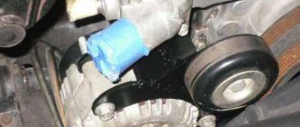
- Using a tensioner, it is necessary to release the tension on the strap and remove it.
- Next, two screws are unscrewed that secure the assembly to the brackets, after which the device is removed.
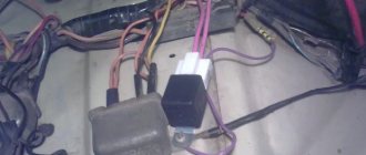
- Now let's start the analysis. First, we dismantle the protective casing and remove the regulator relay, it is removed together with the brush assembly, you need to disconnect the wire from the relay.
- Next, you need to unscrew the four tightening bolts and dismantle the back cover with the stator mechanism.
- Now you need to disconnect the phase contacts of the winding from the rectifier device and dismantle the stator device. All components of the structure necessary for replacement and repair are removed, and assembly is carried out in the reverse order.
Loading …
What is needed for remodeling
If you modernize it, it will be completely, including the injector, and for this you should take a closer look at the Digitronic gas-cylinder equipment. This HBO is praised by many, and it can be installed on Gazelle.
But there is one significant nuance - to equip a car with Digitronic, you need an injection engine, “tuned” to Euro-2 toxicity standards.
And then, modifications for the injector will not end there, because the following components and parts will be needed:
- Injector wiring on the Gazelle - 406 engine does not have it, not to mention the control unit;
- Intake system, including the manifold itself with the injector ramp, throttle position sensor, throttle pipe, idle air control and additional air regulator, connecting pipes and pipes;
Note! Wiring for Gazelle 406 is also available at disassembly sites. But its performance and reliability cannot be guaranteed.
- Injection camshafts. This point is controversial, since it is quite possible to leave carburetors on the car. The main difference between them is the lifting height, which affects the power;
- Electric fuel pump together with a fine fuel filter;
- Mass air flow sensor with connecting pipes;
- Air filter housing with bracket;
- Electric fan (but not required).
Malfunctions
The main malfunctions of the power supply element include a malfunction of the voltage regulator and brush assembly. To carry out repair and diagnostic work, the ZMZ 406 generator must be removed from the vehicle.
Maintenance of the unit includes measuring the output voltage and checking the condition of the contacts for damage or corrosion. If the current flows weakly and the voltage in the on-board network periodically drops, then it is recommended to disconnect the power wires, clean the contacts, and lubricate them using special products. Then the ZMZ 406 generator is connected to the on-board circuit. Let's see if there are any changes. If the work stabilized, then the problem was in the contacts. But if the voltage continues to jump, then it is recommended to dismantle the part and carry out a comprehensive diagnosis.
Removal process
Before replacing the generator on a Gazelle, it is important to remove the negative one, thereby de-energizing the car’s network, and also disconnect the electrical wires from the part. Next, you need to loosen the belt tension using a special mechanism and remove it. Then, having unscrewed the two mounting bolts of the generator from the engine crankcase, we remove the generator itself from the engine compartment.
If the brushes fail, replacing them will not be difficult.
You just need to unscrew the two screws securing the brushes and remove them from the body. But in case of more serious malfunctions, the element must be disassembled and a detailed analysis of the faults.
Gas 3110. Generator repair. Volga
Repairing a generator yourself is difficult and impractical, since a special stand will be required to determine its serviceability and compliance with its characteristics.
| NOTE During electrical tests of the generator, especially in the rectification stage, the equipment used should not produce voltages higher than 14 V to avoid the risk of destruction of some components. |
Therefore, it is better to entrust generator repair to qualified specialists at a service station, where you can also replace the generator from the exchange fund. Such a generator will be 50% cheaper than a new one.
However, before replacing the generator, you can carry out some checks.
Checking the voltage regulator
on a car
To check the voltage regulator, you must have a DC voltmeter with a scale of up to 15 - 30 V, accuracy class no worse than 1.0.
Check the voltage regulator installed on the car in the following order:
- start the engine and let it run for about 15 minutes at medium speed;
- using a voltmeter, measure the voltage between terminal “30” and the “ground” of the generator;
- The voltage should be between 13.3 - 14.6 V.
If there is a systematic undercharging or overcharging of the battery and the regulated voltage does not fall within the specified limits, the voltage regulator must be replaced. In addition, it is necessary to check the condition of the carbon brushes.
Checking the condition of the carbon brushes
Although this work can be done with the generator installed, it is still recommended to remove the generator from the vehicle.
Check the condition of the carbon brushes in the following order:
- unscrew the bolts securing the protective casing and remove it;
- unscrew the two bolts securing the voltage regulator;
- Carefully remove the voltage regulator assembly with brush holder and generator brushes from the generator housing;
- Check the condition of the contact part of the carbon brushes. Check the mobility of the brushes in the brush guides; if necessary, clean the brush holder with trichlorethylene.
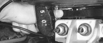
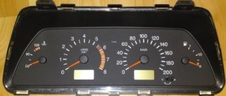
- measure the length “a” (Fig. 9.4) of the carbon brushes protruding from the brush holder. If their length is less than 5 mm, then the brushes should be replaced.
The new carbon brush is 12mm long, so you can tell how much the carbon brushes have worn down. Replacing old carbon brushes with new ones means replacing the entire voltage regulator assembly with brushes and brush holder, since the carbon brushes are soldered into the brush holder. However, you can solder the electrical connection of the new carbon brush yourself if you wish.
Rotor check
The generator field winding is checked for open circuit and short circuit. Connect the tester (in ohmmeter mode) to the rotor slip rings (Fig. 9.5). The tester should show a winding resistance of 2.8 - 3.0 Ohms.
If the tester shows more resistance, then wipe the contact rings with a cloth soaked in trichlorethylene and clean them with glass sandpaper. If a groove with a depth of more than 1.5 mm has formed in the slip ring, then the ring must be re-sharpened on a lathe.
If the tester indicates a break (the resistance is “infinitely large”), first of all, inspect the connections between the field winding and the slip rings. Often they are the reasons for the excitation circuit to break.
Carefully solder these connections with a powerful (at least 100 W) soldering iron or replace the rotor.
Sometimes the slip rings rotate relative to the rotor, which also leads to a break in the excitation circuit. Replace the rotor or glue the spinning ring to the shaft using epoxy glue.
The cause of a break in the excitation circuit may also be the disconnection of the wire from the brush. In this case, replace the rotor or drill a recess in the end of the brush with a diameter larger than the diameter of the wire, fill the recess with glue mixed with graphite filings from the faulty brush and insert the wire.
A short circuit in the field winding is checked by connecting one tester probe (in ohmmeter mode) to the rotor slip ring, and the other to the rotor (Fig. 9.6).
If the needle deviates, try to find and repair the short. Most often it happens at the junction of the excitation winding with slip rings - under the influence of centrifugal forces, the wire breaks and connects to the generator rotor shaft. If you cannot eliminate the short circuit in the field winding, replace the entire rotor.
Note that the field winding can be checked without removing the generator from the car. The slip rings can be accessed by removing the protective cover and the voltage regulator with brush holder.,
Stator check
Also check the generator stator winding for an open or short circuit. To check for open circuit, the tester (in ohmmeter mode) is connected alternately to the ends of the two stator phases.
If the indicator reading does not correspond to 0.1 - 0.11 Ohm, then there is an open circuit in the circuit of the winding being tested.
If a break is found, solder the junction of the broken wires with a powerful soldering iron (at least 100 W), coat it with varnish and dry at high temperature.
When checking the stator winding for an open circuit, pay attention to the readings of the tester when connecting it between the phase terminals. Whenever the tester is connected, its readings should be the same. If the tester shows different resistance, this means that there is an interturn short circuit in the stator winding. This winding should be replaced.
Most often, in the event of a short circuit, the location of the damage can be determined by external inspection - traces of overheating of the wiring are visible.
A short circuit of the stator winding to the housing is determined by connecting one tester probe (in ohmmeter mode) to one of the winding terminals, and the second probe to the stator housing.
If the tester arrow deviates, it means that the winding being tested is shorted to the housing. If you cannot find the short circuit, replace the entire stator.
Source: https://automn.ru/gaz-3110/gaz-43327-10.m_id-6116.m_id2-6118.html
Checking the condition of parts
Regardless of which generator is installed on the Gazelle, the causes of the malfunction, as a rule, can be of the same nature.
They should not have chips or cracks; when pressed with a finger, they should freely sink into the channels of the brush holder, and return to their original position under the influence of a spring.
The length of the brushes should not be less than 4 mm, and if there is severe wear, they are replaced with new ones.
The stator is checked for short circuits between the turn windings and the housing.
This is done by connecting one terminal of the control light to the housing, and the second is alternately connected to one of the three terminals of the turns. In this case, if there is a short circuit to the housing, the indicator light will light up. Having discovered this type of malfunction, it is eliminated or the stator is completely replaced.
To check the stator for a short circuit between the turns, a test lamp is alternately connected to the two terminals of the windings. Moreover, if the light bulb lights up, then there is no break in the turns.
The generator rectifier unit should be cleaned of dust and dirt deposits. Next, you should check the diodes using a test lamp. Due to the fact that diodes of different polarities are placed in each section, they are checked with different battery connection polarities.
Dismantling the generator
You can dismantle the ZMZ 406 generator from the power plant with your own hands. To do this, you will need a key for 10 and 12. Then you can perform the necessary dismantling operations:
- Remove the negative terminal from the battery.
- We unscrew the wires that are connected to the generator.
- Unscrew and loosen the belt tensioner.
- We remove the belt. If the belt is not planned to be changed, then it can only be removed from the pulley of the generator itself.
- Unscrew the nuts securing the unit to the bracket.
- Pull out the fixing bolts.
- We remove the generator.
With the part removed from the car, you can now begin diagnosing the problems. First you need to disassemble the unit. Remove the back cover, remove the voltage regulator and pulley. Next, unscrew the coupling bolts of the generator covers and remove the stator. If necessary, the rectifier can also be removed.
First you need to diagnose the brush assembly and voltage regulator. As practice shows, it is precisely these parts that often have malfunctions. If everything is in order with the parts, then it is worth checking the stator, rotor and coil winding. Usually, if these components are faulty, they can be replaced. But, if a winding or more than two parts have failed, then it is advisable to purchase a new ZMZ 406 generator, since repairing the old one can cost much more.
Disassembly
This section describes a step-by-step process that will help you correctly disassemble the Gazelle generator.
So, first you need to remove the plastic protective cover from the case. Then unscrew the brush block and the voltage regulator, having first disconnected the wiring from it. Next, you should unscrew the four tie rods of the generator housing and remove the housing cover together with the stator. Then, having disconnected the winding terminals from the diode bridge, you need to remove the stator, and, if necessary, the
You can carry out the process of diagnosing generator parts using measuring instruments: E236 or a special test light.
Technical characteristics and principle of operation of the generator set
Gazelle 402 and 406 cars are equipped with generator sets, which are a synchronous three-phase electric motor with electromagnetic excitation. The purpose of this device is to convert rotational motion into electricity, which subsequently powers the battery and all electrical equipment of the car. Gazelle Business or Cummins are equipped with generator sets of models 2502.3771 or 9422.3701, their power parameter is around 1000 W.
Briefly about the technical characteristics of the device:
- the unit implements the right direction of shaft rotation;
- the voltage level produced by the device is 14 volts;
- the maximum current value is 72 amperes;
- excitation of the unit at an air temperature of 25 degrees is 1400 rpm;
- at a rotation speed of 1800 rpm, the generator unit will be able to deliver no more than 40 amperes of current, at 5000 - about 70 amperes;
- the resistance value in the excitation winding at an air temperature of 35 degrees is about 2.3-2.7 Ohms;
- The device uses brushes of the M1 brand;
- the number of auxiliary diode elements is 3, and the power limiters for them are 6.
As for the operating principle, it is based on electromagnetic induction. In particular, when a magnetic flux passes through a copper coil installed inside, a voltage appears at its terminals. Voltage values are proportional to the rate at which a given flow changes. It is then necessary for this current to pass through the coil, this will allow it to be converted.
A rotor device is used as a source of alternating field, which consists of a shaft, slip rings, and a pole system. An equally important component is the stator, which is used to generate alternating current. The latter structurally consists of a winding as well as a core.
Service Features
Basic maintenance details:
- From time to time it is necessary to check the belt tension. If the belt is poorly tensioned, this will cause the unit to operate ineffectively. The voltage in the system will jump, and problems may appear in the operation of electrical equipment. If the strap is overtightened, this will lead to accelerated wear over time.
- Also, during maintenance, it is necessary to check the fastening of the unit, as well as the voltage regulator. If the unit is poorly secured, this will lead to vibrations affecting it, which, in turn, will also affect its service life.
- In addition, you periodically need to clean the unit body from dirt and check the condition of the brush assembly (to do this, it must be dismantled). The same applies to spring pressure and contact wheels. All detected problems must be corrected in a timely manner. If possible, you can also blow off the internal surfaces of the device with compressed air.
- If we are talking about preparing a unit for winter, then as part of maintenance it is necessary to remove the device and diagnose its technical condition as a whole. If necessary, the unit is disassembled and its mechanisms and windings are checked more thoroughly. All identified problems must be corrected. And before assembling the device, it is also recommended to blow it with compressed air, in particular, you need to pay attention to the rotor. It is better to replace the lubricant in bearing elements; to do this, the protective ring is dismantled, and the part itself is washed. As for the lubricant itself, it is filled to approximately 70% of the total volume, after which the device is assembled. There is no need to add lubricant to sealed bearings (the author of the video is the prosto gazelle channel).