The Solex carburetor is one of the main components in the fuel supply system, on which the efficiency of the entire vehicle depends. These carburetors are very popular today.
The main reasons for their popularity are fuel efficiency and high efficiency of your power unit. However, to achieve such indicators it is necessary to configure it.
Setting the float chamber level
First of all, you need to pay attention to the fuel level in the float chamber.
The adjustment procedure is as follows:
- It is necessary to start the engine and carefully apply gas to check the efficiency of the carburetor;
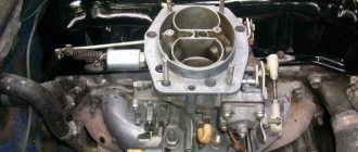
- Remove the air filter from the carburetor and the fuel hose.
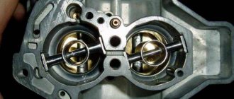
- Unscrew the 5 bolts and remove the carburetor cover. Be sure to vertically so as not to damage its floats. Place this cover on a flat surface.
- When removing the carburetor cap, the fuel level should be at the red lines. The fuel depth must be measured. This figure should be about 29 mm. The procedure should be carried out immediately after removing the carburetor cap, since gasoline tends to evaporate.
- The height of the floats needs to be adjusted. We measure the distance from the cardboard gasket of the carburetor cover to the top of each float.
- The recommended figure is 34 mm. If necessary, you need to bend the levers and float tongue.
- Let's start adjusting the full stroke of the floats. The permissible lift of the lower angle of the float is 15 mm, and the full stroke of the float is 25 mm. Make sure that the edges of the floats are parallel to the sealing surface of the cover.
Idle speed setting
After setting the level in the float chamber, we assemble the carburetor and warm up the car engine to operating temperature. In this video, they will tell you and show you how to set the idle speed in a Solex carburetor, as well as the main reasons for its absence.
Next, we turn it off and carry out the following operations:
- Using a flat-head screwdriver, tighten the mixture quality screw until it stops (position 7).
- We turn it back from this position 4 - 5 turns.
- We start the engine, do not forget to completely remove the choke, and using the mixture quantity screw (position 6) set the minimum engine speed to about 800 per minute so that the engine runs stably.
- We tighten the mixture quality screw until the engine starts to run unstably. Then we turn it back 0.5 - 1 turn, which should bring the engine to a relatively stable position.
- Using the mixture screw, set the engine speed to about 800 - 900 per minute. If the engine starts to stall, unscrew the mixture quality screw a little more.
When setting the idle speed, some problems may arise:
The engine does not slow down when the mixture screw is tightened (a lot of fuel gets into the idle channel and this screw cannot shut it off).
Causes:
- large jets installed;
- the solenoid valve is not tightly screwed in, and fuel is sucked past the nozzle;
- deformation of the nozzle seat or itself.
So, for example, if the engine stalls when removing the wire from the solenoid valve, this means that the jet is installed too large.
Carburetor adjustment
Each of the carburetors is adjustable to several values. After performing this operation, change:
- filling the float chamber with gasoline;
- the value of the maximum idle speed;
- saturation of the fuel-air mixture entering the engine.
Adjusting the quality of the mixture is quite easy. Every car enthusiast can do this:
- On a warm engine, using the mixture quality adjustment screw, set the number of revolutions to no more than 900 on the tachometer;
- We reduce the quality of the mixture to the maximum possible by tightening the adjustment screw. We bring the engine to very low speed;
- Gradually unscrewing the screw, we bring the speed to normal so that the engine runs smoothly. You can’t overdo it here; it’s better to perform the operation again. Increased idle speed will increase fuel consumption, so additional adjustments are made.
There are situations when the speed has to be increased due to failures in the engine. For example, if the speed does not change when rotating the screw. There are several reasons for this breakdown. You need to pay attention to:
- solenoid valve jet - it may be clogged;
- channel located under the mixture quality adjustment screw. If gasoline is of poor quality, it becomes clogged;
- solenoid valve - it may be the one that is faulty.
Checking the serviceability of the valve is quite simple. With the engine turned off, disconnect the wire from the electromagnet, unscrew the solenoid valve and disconnect the fuel nozzle. Now turn the key in the ignition switch and bring the wire removed from the valve.
A click and retraction of the valve stem into the body indicates the serviceability of the electromagnet. Otherwise, we change this device unit. Craftsmen advise an easier way. With the engine running, pull off the wire. If the engine stalls, you can continue working - the valve is working properly.
If debris gets into the nozzle, it should be cleaned. Cleaning is very simple. The jet can be purged using a pump or compressor. Often the specks are so small that they are not visible, but it is better to play it safe and, if the part is removed, then it is blown out to eliminate this problem. After completing all the operations, we put the nozzle in place and check the operation of the system.
It is not always possible to clean the idle air passage under the mixture adjustment screw on the road. Often it becomes so clogged that it cannot be vented, and disassembling the carburetor is necessary to eliminate the problem. Only after this does it become possible to clear this channel. In such a situation, there is a temporary solution.
Using a wrench, loosen the fastening of the solenoid valve on the carburetor until the engine is operating normally and drive home. In this case, gasoline passes by the idle fuel jet and this leads to increased fuel consumption. The main “symptom” of this malfunction is interruptions at minimum speeds and the engine turning off when the gas pedal is depressed, so mandatory cleaning of the channels and subsequent adjustment will help get rid of the breakdown.
Remember - tuning and adjustment is carried out only on a warm engine, but before this it is often necessary to replace the nozzle by installing a part from the kit. We'll look at how to do this correctly below.
Selection of jets
Some parameters of serial carburetors are far from the standard ones, since the dimensions of some parts have manufacturing deviations. An interesting and very useful video from which you will learn how to modify the Solex 21083 carburetor.
Thus, the spread in the parameters of some serial carburetor parts can reach up to 5%. Therefore, when adjusting the carburetor, make sure that the jets are in good working order. The selection of jets is carried out taking into account the working volume of the car.
If the engine has a large displacement, then it is necessary to install small jets, since an increase in volume requires more air passing through the diffuser, which affects gasoline consumption. Their adjustment should begin with the fuel jet, and then, if necessary, move on to the air jet.
You need to have several jets available with higher and lower productivity than the installed one.
Our actions:
- Using a wire, secure the throttle valve of the second chamber to eliminate its influence.
- Next, we select the jets, for example, the jet marked “107.5”, which is our basic one, change to “105”, and then “97.5”. We reduce the throughput of the jets until dips appear when the throttle is open or twitching when driving. When these signs appear, you should unscrew this jet and replace it with the previous one, which had a slightly higher performance.
- If dips occur when starting the car, you should enrich the mixture slightly by adjusting the idle system.
If you are trying to increase the efficiency of your car, then it is not recommended to reduce the flow area of the main fuel nozzle of the second chamber, since the acceleration process will be much longer, and all savings will be reduced to zero.
Types of jets and their ratio
Motorists are quite interested and sometimes need to find out where and what jet is installed on the carburetor of their vehicle from the factory.
Having studied the principle of operation, it is worth taking a look at the types of jets.
Parts differ depending on the functions performed. This is also affected by the location in the carburetor system. As a result, we can distinguish the following varieties:
- fuel;
- air;
- compensation;
- with idle speed.
The element is assessed based on its operational properties. It is required to determine the volume of liquid that passes through the hole in a certain period of time. Such elements are marked. This is a 3-digit number. It is applied mainly to the end part.
Using the marked number you can find out about the performance of the jet. It is calculated in cubic centimeters at a pressure of 1000 millimeters of mercury. This is the volume of fuel passing through the hole.
The holes in the jet are strictly calibrated. If you use the wrong cleaning tools, the part can be completely damaged. And then only replacement will solve the problem.
Non-ferrous metals are used to make jets. This causes the parts to be susceptible to deformation. Therefore, you should be extremely careful when cleaning.
For each chamber, it is necessary to manufacture a corresponding jet, that is, fuel or air. The choice is made based on the cross-section of the carburetor diffuser. Usually, special sets of jets are produced for different cars and models, which differ in the diameter of the hole provided. This largely answers the question of what kind of jet should be in the carburetor in order for the engine to provide optimal performance.
This feature should be taken into account here. To increase dynamics and improve acceleration of the car, a large main (fuel) jet is often installed. This in parallel affects the increase in fuel consumption.
Increasing the diameter of a part by several orders of magnitude may not improve dynamics, but at the same time significantly increase fuel consumption.
To determine the optimal ratio of two jets for your carburetor, it is recommended to look at the owner's manual and take into account the manufacturer's recommendations. The ratio can be from 80 to 100 to 125 to 165. Depending on this, the mixture can be lean, overly enriched, or optimal.
Adjusting the accelerator pump
Accelerator pump metering systems
The main task of the accelerator pump is to supply a smooth and powerful stream of gasoline through the open throttle valve of the carburetor (dripping and sluggish streams are not allowed). The stream of gasoline should enter directly into the manifold, without touching the walls of the diffuser and throttle valve.
Flowing of gasoline down the diffuser stack or throttle valve is not allowed, since the car will become very blunt and jerky when you press the gas sharply.
An accelerator pump with two spouts must be installed in different chambers. You can insert two spouts into the primary chamber - this can increase the agility of the car, but also lead to excessive “overflow”.
Setting the transient mode of carburetor operation
At idle speed, the carburetor throttle valves close and a high vacuum area is created under them, which allows gasoline to be “sucked” out of the idle channel through the nozzle. If the damper is opened sharply, the vacuum decreases sharply, which disrupts the normal operation of the main dosing system of the first chamber and a failure appears.
To eliminate these symptoms, adjust the idle jet or accelerator pump nozzles. The adjustment must be made on a warm car engine.
The idle jets or accelerator pump are changed one by one to prevent dips and delays when you press the gas sharply.
You may need to adjust the idle speed a little. Over-enrichment is not transiently displayed as black smoke coming from the exhaust pipe.
Do-it-yourself interior tuning. How to do this and what is needed for this can be found on our unique website.
From here, you can learn how to do tuning a Chevrolet Niva with your own hands.
In this informative article, you will learn how to polish a windshield with your own hands.
It is recommended to install an accelerator pump with 40x40 nozzles, and an idle nozzle with parameters from 35 to 40. If there are dips from a lean mixture and it is not possible to adjust the idle speed due to the idle nozzle being too large, then both accelerator pump nozzles can be placed in the first camera as shown in the picture.
Setting up a second camera
As a rule, the second chamber of the carburetor is not adjustable, since all the shortcomings of the factory jets are compensated for by the econostat. The fact is that at high speeds, when a vacuum occurs in the carburetor, additional gasoline is supplied through the econostat, which makes it possible to enrich the mixture.
Only the accelerator pump nozzle can be adjusted if its jet does not fall between the diffuser wall and the throttle valve.
All of the above techniques for tuning the carburetor are basic in its regulation, however, some craftsmen can additionally drill channels and throttle valves, and solder epulsion tubes.
The Solex carburetor (DAAZ) is one of the most popular devices in the list of carburetor metering systems, since with the right approach it is possible to flexibly configure carburetors of this type. For this reason, car enthusiasts install Solex carburetors on different engines, after which they are further adjusted, achieving the required fuel efficiency indicators, quality of mixture formation at power and other operating modes of the internal combustion engine.
After installing Solex on the engine, it is often necessary to configure this device. To solve the problem, you can contact a service center, where a specialist in setting up the carburetor will perform all the necessary operations. You can also adjust the carburetor yourself. In this article we will talk about how to adjust the quality of the mixture on a Solex carburetor, how to adjust the fuel level and adjust the float chamber of the Solex carburetor, adjust the idle speed, etc.
Read in this article
Solex carburetor: setting and adjustment
Before starting the setup work, if it is necessary to adjust the carburetor air damper, the fuel level in the chambers, setting the idle speed and other manipulations, it is necessary to separately study the design of the carburetor system, the location of the jets and other basic elements (econostat, economizer, float, first and second chamber, dampers, etc.) You should also pay attention to how the cover is removed and the carburetor is disassembled.
You need to start setting up by setting the fuel level in the float chambers. The recommended method is to set the specified level according to the position that the floats have in relation to the carburetor cover. All manipulations are carried out using a separate template. Note that, as practice shows, this method cannot in any way be considered optimal, since when installing Solex on a car, it should be taken into account that the fuel pump on one specific vehicle may differ from the fuel pump on another car. There may also be other differences in the power supply system. The result is that the pressure on the carburetor needle (carburetor shut-off valve) is also different. Most often, after tuning according to the template, fuel enters the carburetor in large excess. In order to accurately set the gasoline level in the carburetor and adjust the Solex carburetor float successfully, you must follow the steps described below.
- Usually, immediately after installing Solex on different internal combustion engines with different displacements, even without preliminary adjustments, the engine should still start. The engine must be started, after which the power unit should run for about 10 minutes. When running at idle, you can lightly press the gas and increase the speed to avoid the engine shooting into the carburetor or exhaust system.
- Then the power plant can be turned off, after which it is necessary to remove the fuel supply hose. It is recommended to prepare a rag to remove any remaining gasoline that splashes after removing the said hose. The hose is removed so that after removing the carburetor cap, gasoline, which is under pressure in the hose, does not spill into the carburetor chamber. In other words, excess fuel entering the chamber can interfere with the accuracy of the measurements.
- Now you can unscrew the screws securing the carburetor cover, then you need to remove the cable that controls the “choke”. The next step is to carefully lift the carburetor cover. The specified cover should be lifted in a strictly horizontal position so as not to cause damage to the floats themselves.
- Next, you should prepare a ruler or caliper. With these tools you need to measure the distance that is obtained from the fuel itself in the chamber to the adjacent surface of the carburetor cover. The indicated distance from the surface of the cover to the surface of the fuel should be about 2.5 cm. We add that the distance must be measured in both chambers. This distance may vary, taking into account that the collector is not in a strictly horizontal position. Based on the difference in distances in both cameras, an average value is selected.
If no drops of fuel were noticed, then all that remains is to re-measure the fuel level in the chamber using the already known method. If the result is positive, this part of the setup can be considered complete. If the level again differs from the norm, then the level should be adjusted again. Note that setting the level with the engine turned off during manual pumping is not correct, since after starting the internal combustion engine the carburetor will still overflow, especially on engines where the return line has been blocked.
Solex carburetor: idle speed adjustment
The next step after adjusting the fuel level in the carburetor float chamber is to adjust the idle speed. To set up, you must first warm up the engine until it reaches operating temperature. After warming up, the unit should be turned off.
At the very beginning, you need to find the air-fuel mixture quality screw, which is rotated using a flat-head screwdriver. The specified screw is located in the hole, which is made in the lower part of the carburetor.
- The quality screw must be tightened until it stops. Screwing is carried out clockwise, and there is no need to apply force, as the thread can be damaged. After the screw stops, you should turn it back from the stop position by 4-6 turns.
- Now the engine should be started, the choke should be removed. Then you should set the minimum permissible speed by turning the quantity screw. Such minimum speed can be considered an indicator when the engine operates stably and steadily. Also, the vacuum in the vacuum advance fitting should be minimal. A fairly simple way to determine the vacuum is to close the tube that goes into the so-called vacuum advancer with your tongue. If the idle speed is in the range from 600-1200, the carburetor is fine.
- Next, the quality screw must be slowly tightened until the operation of the unit begins to lose stability. As soon as the engine begins to operate unstably, you should unscrew the screw back one or one and a half turns, catching the position when the motor is operating stably again
- We return again to the quantity screw, with which the idle speed should be set to 800-950 rpm. We set the speed screw at XX to about 850-900. If the engine stalls when setting such speeds, then you need to unscrew the quality screw.
- The quality and quantity screws are adjusted until the required idle speed is set, the vacuum in the advance tube will be minimal, and the internal combustion engine itself will be able to operate stably.
This problem arises for a number of reasons. First of all, a large idle jet can be installed. You should also pay attention to how tightly the solenoid valve or plug is screwed in. If the fit is not tight, excess gasoline may be sucked in bypassing the idle jet. Also, one should not exclude possible problems with the jet itself, as well as with its seat. To more accurately understand the reason, you will need to remove the solenoid valve wire with the engine running and idling. In this case, after removal, the unit should quickly stall. If this is the case, then the cause is most likely a large idle jet. The solution will require installing a smaller jet.
Selection and modification of Solex carburetor jets
The selection and modification of jets on Solex carburetors is carried out in two cases: if it is necessary to increase the power indicators of the car engine (quick start, throttle response, increased speed) or to reduce the engine fuel consumption from the rated values. “Solex carburetor jets” is a table of jets that needs to be opened before starting their selection and modification.
In the case of increasing power, the capacity of the fuel jets of the GDS is usually selected and increased (the fuel mixture is enriched). If it is necessary to improve fuel efficiency, increase the capacity of the air jets of the gas pumping station (lean the fuel mixture). In any case, it is necessary to install jets on the carburetor with a modified hole cross-section and a flow rate different from the nominal value (the marking on the jets indicates the diameter of the hole and corresponds to their specific flow rate).
Before carrying out work, you must make sure that the carburetor and engine are operating normally with standard jets. It is also recommended that before modifying the carburetor, bring the vehicle’s power supply system and ignition system into proper condition. If the car engine consumes gasoline in buckets or triples or even doubles, it makes sense to carry out a full diagnosis of the engine systems, bring everything back to normal, and only then begin modifications.
It should be remembered that when working with a carburetor, it is necessary to adhere to a certain pattern: an engine of a certain volume corresponds to a carburetor with a certain cross-section of diffusers, fuel and air jets of the main metering systems. A change in one or more components of this chain leads to a clear change in the operation of the engine. The increase or decrease in the throughput of the jets should be small and gradual - within hundredths of a millimeter. Therefore, for modification, it is better to purchase an additional set of fuel and air jets for the gas pumping station and perform all manipulations on them. We put the original jets back if the experiment fails.
Options for modification and selection of jets on Solex carburetors
— Install air or fuel jets from another carburetor, from another engine
You can choose from the lists below.
Table of sizes and applicability of GDS fuel jets for Solex carburetors
| Carburetor models | 1st camera | 2nd camera |
| 2108-1107010 | 97,5 | 97,5 |
| 21081-1107010 | 95 | 97,5 |
| 21083-1107010 | 95 | 97,5 |
| 21073-1107010 | 107,5 | 117,5 |
| 21051-1107010 | 105 | 110 |
| 21083-1107010-31 | 95 | 100 |
| 21083-1107010-35 | 95 | 100 |
| 21083-1107010-62 | 80 | 100 |
| 21412 | 95 | 95 |
GDS fuel jet of the first chamber of the Solex carburetor 21083
Table of sizes and applicability of GDS air jets for Solex carburetors
| Carburetor models | 1st camera | 2nd camera |
| 2108-1107010 | 165 | 125 |
| 21081-1107010 | 165 | 135 |
| 21083-1107010 | 155 | 125 |
| 21073-1107010 | 150 | 135 |
| 21051-1107010 | 150 | 135 |
| 21083-1107010-31 | 155 | 125 |
| 21083-1107010-35 | 150 | 125 |
| 21083-1107010-62 | 165 | 125 |
| 21412 | 160 | 100 |
Air jets, fuel jets, emulsion tubes and Solex carburetor wells
— Modify existing jets
Thin drills of 1 mm, 1.5 mm, 1.75 mm, 2 mm, etc. are available for sale. They can be used to drill nominal jets to the required size, increasing their throughput. In some cases, you can solder the nozzle hole with tin and drill it again.
— Jet selection technology
We begin the selection with the fuel or air jets of the GDS of the first chamber of the carburetor. We install a jet of reduced or increased cross-section (usually only one hundred square meters) instead of the standard one and check the dynamic characteristics of the car or its fuel efficiency. If necessary, we adjust the idle speed using the “quality” and “quantity” screws.
We install an even larger jet and check the dynamics or efficiency. And so on several times until obvious failures in engine operation appear in different modes. The work is painstaking, requiring time and nerves. Then we take a step back, installing a jet of the previous size. We carry out a similar adjustment of the second chamber of the carburetor (in most cases we are limited to the first).
This process (in combination with other modifications to the carburetor) is described in detail in the articles on the website “Reducing the fuel consumption of a car engine with a Solex carburetor”, “Increasing the power and throttle response of a car engine with a Solex carburetor”.
Checking the throughput of the jets to monitor compliance with their markings can be checked by making a home-made device (See “Marking and throughput of Solex carburetor jets”).
Notes and additions
— The selection of jets described above is a minimal intervention in the operation of the carburetor with minimal consequences (increase in power by 5 - 10 percent or efficiency within a liter per hundred). You can tune your carburetor more strongly and effectively if you add modifications to the carburetor diffusers, both small and large, to the selection of jets, select emulsion tubes, modify the carburetor mixing chambers, accelerator pump and change the sequence of opening the throttle valves. A set of measures will allow you to fully reveal the hidden reserves of the engine, which will ultimately change and improve the necessary characteristics of the car to suit the requirements of each specific car owner.
Twokarburators VK - More information on the topic in our VKontakte group, on Facebook Twokarburators FS and on Odnoklassniki - Twokarburators OK
More articles on Solex carburetors
— Improvement of the “quality” screw of the fuel mixture of the Solex carburetor
— Modification of the idle system of Solex carburetors
— Refinement of the cardboard gasket for the Solex carburetor
— Modification of the Solex carburetor air damper drive
— Options for modifying the accelerator pump of the Solex carburetor
— Refinement of the upper part (cover) of the Solex carburetor
— Modification of the Solex carburetor idle system
Jets and accelerator pump
Owners of carburetor cars know that jets change, but they do not always understand why jets are needed and how their size affects the operation of the carburetor. Let's start with the fact that the engine sucks in air through a special hole made in a large diffuser. At the same time, a certain amount of fuel is drawn through the fuel nozzle. The engine displacement directly affects how much air the engine will draw through the diffuser in a certain time, as well as the amount of gasoline sucked in parallel with the air.
Now let's talk about the accelerator pump. The accelerator pump delivers additional fuel when the throttle valve opens, allowing for more efficient acceleration. The pump is activated using a special cam. On engines with a Solex carburetor installed, the indicated accelerator pump cam must be set to the largest one.
You should also pay attention to the so-called “spout” of the accelerator pump. When the valves are opened, fuel should flow in a clear stream and not drip even with a slight throttle opening. It is also important what position the nose occupies. The stream of gasoline must fall exactly into the area between the diffuser wall and the throttle valve, that is, the fuel is jetted directly into the manifold. The jet must not hit the diffuser or damper. If this happens, then after sharply pressing the accelerator pedal the car will not accelerate immediately, and a failure will occur. Self-refinement of the carburetor involves installing two spouts in the chambers to obtain better performance from the engine, or only one spout in the first chamber of the carburetor for a more economical mode.
Carburetor jets VAZ 2107
VAZ 2107 cars are available in two trim levels - with carburetor and injection engines. The main differences between these types of engines lie in the operating principles of the power and ignition systems: as the name suggests, one of them uses a carburetor to prepare the fuel mixture, the other uses an injector. Accordingly, they have different maintenance requirements.
So, in a carburetor engine, the main unit of the power system is the carburetor. It is here that the fuel mixture is prepared before it is supplied to the cylinders; accordingly, the operation of the entire fuel system directly depends on the operation of the carburetor.
According to the recommendations of the VAZ 2107 car manufacturer, it is recommended to carry out vehicle maintenance at intervals of 10,000 km. This also applies to the carburetor, as one of the main elements.
The weak point that every carburetor has is the jets. Roughly translated from French, the word jet means “to splash,” and in relation to the operation of a carburetor it can be interpreted as injection or feed. It is through the gas chambers that gasoline and air enter. The design of the carburetor of the VAZ 2107 car contains jets of different capacities and different purposes. Some of them provide the engine with the fuel mixture at low speeds, some - at high speeds, and a separate one is responsible for the supply of fuel in idle mode. The digital marking of the nozzle indicates the amount of liquid that can pass through the hole in one minute.
Below is a list of jets provided for in the design of the VAZ 2107 carburetor:
- Main fuel primary and secondary chambers;
- Main air chambers of primary and secondary chambers;
- Accelerator;
- Fuel transition system secondary chamber;
- Fuel idle.
The main problem that periodically arises in the operation of the VAZ 2107 carburetor is that the jets become clogged, as a result of which their throughput is reduced. During maintenance, it is recommended to blow or flush them using special liquids that are used to flush the carburetor. According to the instructions for using these fluids, the jets can be processed superficially, without disassembling the carburetor. Blowing can be done in the same way.
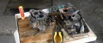
Often, these measures are enough to restore the functionality of the VAZ 2107 fuel system. But if there is significant clogging, you will still need to disassemble the carburetor and alternately unscrew and wash the jets. It is better to do this on a flat surface, covered with newspaper or a clean rag, so that the large number of small parts that make up the carburetor do not get lost or mixed up.
After cleaning and assembly, adjustment at idle and under load is recommended. For this, special adjusting screws are used. First, the idle speed is adjusted, achieving stable engine operation at a speed of 800-1000 rpm. After this, the efficiency of the engine under load is checked, the absence of failures when transitioning from idle to maximum speed. When they appear, use the quality screw to increase the amount of fuel in the mixture, while simultaneously tightening the quantity screw to set the idle speed to the previously specified value.
However, when using low-quality fuel, the VAZ 2107 carburetor becomes dirty much faster and the need to clean the jets may arise much earlier. The first sign of contamination is a drop in idle speed. In the event of significant contamination or the occurrence of other, more serious malfunctions, the engine stalls in idling mode, and when operating under load, it loses throttle response.
One of the countermeasures to prevent this problem from occurring is the installation of an additional fuel filter to finely purify gasoline from mechanical impurities. However, the filter cannot protect the carburetor from contamination 100%. Therefore, it is strongly recommended to blow out or flush the carburetor during the next routine maintenance of your VAZ 2107.
Carburetor transition setting
While the engine is idling, the throttle valves are closed. A vacuum (vacuum) is formed under the dampers. Thanks to this vacuum, gasoline is sucked out through a small idle channel and nozzle, and the engine itself runs smoothly at idle. If you open the damper sharply, then the vacuum also weakens. Moreover, this vacuum is not enough for normal operation of the MDS (main dosing system) in the first chamber, and the idle system and accelerator pump are not yet capable of normalizing engine operation. In other words, when you sharply press the gas after idling, there is a delay in the response to pressing the accelerator pedal.
To minimize or completely eliminate this failure, a transition system is used in the carburetor device. This diagram is a hole-slot made above the throttle valve in the first chamber. At the moment you press the gas pedal, the slot-shaped hole appears in a zone of high vacuum, due to which intensive fuel suction occurs parallel to its supply through the idle jet.
Let's go back to the settings. After the carburetor has been installed, many cars experience a failure when starting from a stop, reactions to pressing the gas pedal are slow, and the engine may start shooting at the carburetor or stall. In such a situation, the transition system may be to blame. In order to normalize the operation of the carburetor, it is necessary to correctly select the cross-section of the “spout” of the accelerator pump and the size of the idle jet.
It is important to know that the nozzles in the first chamber do not need to be touched, and the indicated failures should not be attempted to be eliminated by replacing the nozzles of the main dosing system. To solve the problem, use a previously built carburetor to correctly select the idle jet and the accelerator pump spout. The selection must be made after the internal combustion engine has warmed up, the choke must be removed.
In practice it looks like this:
The level in the float chamber was previously set and the idle speed was adjusted. A warm engine idles normally without chugging. A stream of gasoline from the accelerator pump nozzle hits the manifold. Now you can sharply press the gas pedal. What is needed is the sharpness of the press, and not how hard the pedal was pressed (to the floor, half a stroke or ¼). Normally, the motor should immediately respond and spin up, that is, the speed increases without delays or failures. If the response to a sharp press on the accelerator is slow or there is a noticeable pause before the speed increases, then you should go to the settings.
To accurately determine the cause, you need to press the gas pedal again, but this time smoothly and not sharply. If in this case there is an even increase in speed (without pauses, dips or delays), then you should pay attention to the idle jet and the pump spout, since the main dosing system has nothing to do with the failure. If, when you gently press the gas, the engine spins up poorly, the unit itself begins to work jerkily, hums, vibrates strongly, etc., then the problem lies in the selection of jets for the first chamber. In other words, excessive enrichment or leanness of the mixture occurs after the carburetor switches to power mode after pressing the accelerator. An indirect sign of a too “rich” mixture during operation in transition mode is that the engine emits black smoke and the smell of gasoline comes from the exhaust system. The specified smoke and smell appear after sharp throttling.
To remove the dip, you must carefully select the idle jets to match the pump spout or vice versa. This is done until the delay disappears when you sharply press the accelerator pedal. In parallel with this, it may be necessary to re-adjust the idle speed, since replacing the XX jet will make changes to the operation of the idle system. Let us add that if the mixture remains lean and there is a dip, and the idle jet is too large and it is not possible to adjust the idle speed, then you can install a paired pump spout, after which both tubes are bent into the first float chamber.
Idle system design
The designs of modern carburetors contain not only the main metering system. It alone would not allow obtaining the necessary mixture composition to maintain normal engine operation in no-load mode, in other words, when the engine should be idling. The system of the same name is responsible for normal operation in idle mode. Let's consider one of the options for its design.
Design of the idle system: 1 - transition hole;
2 - air channel; 3 - idle mixture screw; 4 — hole for low idle speed; 5 - fuel channel; 6 - fuel nozzle combined with an emulsion tube. The idle system includes two fuel supply holes. They have special names: transition hole 1 and low idle speed hole 4 (location options on a real carburetor are shown in the figure below). The transition hole is located under the throttle valve, in close proximity to its trailing edge. The low idle speed hole is located behind the throttle valve, a short distance away at the point where the vacuum is greatest when the throttle valve is closed. This situation is due to the desire to ensure the easiest flow of fuel from the low idle speed hole.
Options for the location of fuel supply holes: 1 - transition hole; 2 - hole for low idle speed
In the fuel supply channel 5 of the idle system there is a nozzle 6, which limits the flow of fuel when idling. In the same channel there is an emulsion tube (often combined with a jet), in which the fuel is mixed with air entering through air channel 2.
Fine-tuning elements include screw 3, which regulates the cross-section of the air channel. In this design, the screw influences the composition of the mixture. Below we will consider a design in which a similar screw regulates the amount of mixture.