Malfunctions that occur during the operation of the crankshaft and their causes
Malfunctions and breakdowns in the crank mechanism can occur in a variety of its components. To reduce the risk of these troubles to a minimum, you need to know why they occur. Most often this is carbon deposits on parts and their wear. The most common failures of crankshafts occur from the use of low-quality automobile fuel and oil. This is especially fraught with diesel engines, which are demanding on the quality of fuels and lubricants, which can damage not only the crankshaft. Rare oil changes, untimely replacement of fuel, air and oil filters - all this also carries a potential threat of breakdowns. The malfunction may be caused by engine overheating, as well as leakage and a decrease in the level of engine oil in the engine.
Overheating the engine can even lead to seizure. To prevent this from happening, fill in high-quality coolant and monitor the condition of the cooling system.
It happens that the problem is in the power system or ignition. Then the mixture does not burn completely or unevenly.
Another common cause of breakdowns is the use of low-quality spare parts. Do not buy a fake and use the services of trusted car services.
Repair technology
The main purpose of overhauling a crankshaft is to restore the service life of the piston group and crankshaft. To do this, the seats are restored, fingers and liners are replaced.
Pistons and pins
The piston, which is conventionally included in the crank mechanism of a car engine, is made of aluminum alloys. The finger is made of alloy steel and wears out less.
The pistons have their mirror and the geometry of the grooves for the rings and bosses, inside of which the pin is located, restored. The dimensions of the piston pin are selected at an air temperature in the workshop of 20 degrees, depending on the size group of the piston.
Connecting rod repair
Connecting rods are mainly made from steel 40G, 40X or St45; the following are considered characteristic defects:
- production of metal seats;
- hole wear;
- change in geometry (twisting and bending).
The kinematic element of the mechanism is rejected in case of emergency bending, breakage and crack opening. In other cases, bending and twisting are eliminated by heating to 500 degrees to relieve internal stress. The seating surfaces are milled and then ground to the next resize.
After which, the operation of the crank mechanism again satisfies the requirements of GOST regulations. It is prohibited to remove a metal layer larger than 0.2 - 0.4 mm for diesel engines and carburetor internal combustion engines, respectively. Otherwise, the kinematic diagram of the unit is disrupted.
Crankshaft restoration
The main nuances of crankshaft repair are:
- the part is made of high-strength magnesium cast iron, DR-U, 50T, 40X or St45 steels;
- the main defects are bending and wear of steel of the seats;
- keyways wear out less frequently, threads are damaged, and cracks open;
- An assembly of a crank mechanism with worn-out seating surfaces and damaged threads is considered repairable;
- cracks larger than 3 mm lead to crankshaft rejection.
After washing the oil channels and external surfaces, the product is examined with a flaw detector. The excavation is restored by fusing Sv-18KhGSA wire with a groove for repair parameters. Keyways are milled to a specified finish. In this case, the gear installation diagram must be observed.
After grinding, the crankshaft is balanced on a dynamic installation BM-U4 or KI-4274.
Thus, the crank mechanism of the crankshaft is easier and cheaper to maintain in working condition. To do this, you need to undergo timely maintenance and contact service specialists at the slightest extraneous sound in the cylinder block. In this case, even major repairs will cost less.
The principle of operation of the mechanism
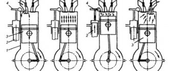
We will consider the operating principle of the crank mechanism in a simplified manner using the example of a single-cylinder engine. This engine includes:
- crankshaft with two main journals and one crank;
- connecting rod;
- and a set of CPG parts, including a liner, piston, piston rings and pin.
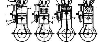
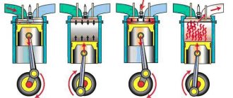
Ignition of the combustible mixture occurs when the volume of the combustion chamber is minimal, and this is ensured by the maximum lifting of the piston inside the liner (top dead center - TDC). In this position, the crank also “looks” up. During combustion, the energy released pushes the piston down, this movement is transmitted through the connecting rod to the crank, and it begins to move downward in a circle, while the main journals rotate around their axis.
When the crank is rotated 180 degrees, the piston reaches bottom dead center (BDC). After reaching it, the mechanism operates in reverse. Due to the accumulated kinetic energy, the flywheel continues to rotate the crankshaft, so the crank rotates and pushes the piston up through the connecting rod. Then the cycle repeats completely.
If we consider it more simply, then one half-turn of the crankshaft is carried out due to the energy released during combustion, and the second - due to the kinetic energy accumulated by the flywheel. Then the process is repeated again.
Something else useful for you:
- What is an engine piston? Features, operating principle and purpose
- All the best ways and means of decoking piston rings with your own hands
- What is engine water hammer, how does it happen and what consequences does it cause?
KShM design
Unlike other car components, the design of the crank mechanism conventionally includes part of the piston group and the crankshaft. The crankshaft consists of moving parts and fixed elements. They have one or more degrees of freedom:
- connecting rod and piston;
- compression, retaining and oil scraper rings;
- piston pin and retaining ring;
- liners, mounting bolt and connecting rod cover;
- flywheel and crankshaft;
- counterweight and connecting rod journals, main ones;
- inserts.
Fixed elements include the cylinder head and block.
Depending on the design of the internal combustion engine and the number of cylinders, the kinematics of the crank mechanism changes slightly:
- in an in-line engine, the plane of the crankshaft and cylinders completely coincide;
- in the VR-shaped motor there is a shift at an angle of 15 degrees;
- in the W-shaped drive, the displacement value reaches 72 degrees.
In other words, in an in-line engine, the working cycle is carried out alternately by 4 cylinders, which allows the load on the crankshaft to be evenly distributed. To achieve compact dimensions, internal combustion engines with a large number of cylinders are placed in a V-shape. This also makes it possible to soften the load on the crankshaft by dissipating part of the energy.
Sectional drawing of the KShM
To ensure that the characteristics of the crank mechanism are stable during overloads (high temperature, high pressure and speed, difficulties with lubrication supply), instead of ball/roller bearings, sliding elements with connecting rod and main bearings are used. The unevenness of the angular speeds of the shaft in individual cycles is smoothed out by a massive flywheel due to the inertia of this part.
When and how often should engine diagnostics be carried out?
Do not underestimate the impact of minor malfunctions on engine performance - measures must be taken already at the stage of their occurrence
If you do not pay attention to them, you will very soon have to face repairs to the power unit. Repairing this unit is an expensive pleasure.
We list the signs that make it necessary to diagnose the motor:
- Fuel consumption has increased significantly. The type of fuel doesn't matter.
- You have to add oil often and a lot.
- A significant cause for concern is a drop in vehicle power.
- Difficulties arise with shifting gears, engagement occurs jerkily.
- The appearance of unusual sounds when starting the engine.
Thanks to diagnostics, you can find out how much engine repair is required and what its cost will be. For diesel cars, it is necessary to diagnose the engine once every six months. In addition, it is necessary to carry out special preparation of the machine for the winter and summer seasons. Professional auto mechanics advise diagnosing the internal combustion engine not only when a malfunction is suspected, but also regularly for preventive purposes. Often this method can prevent serious damage to the power unit.
The internal combustion engine is assembled in the reverse order of disassembly:
- The piston group is assembled: - pistons with connecting rods, - oil scraper rings are put on, then compression rings (the gaps should not match);
- The pistons are immersed into the cylinders through a special device that presses both rings into the piston grooves;
- The crankshaft is installed;
- The connecting rods with liners are fixed to it one by one by arc-shaped plates with bolts;
- The following are returned to their place: - cylinder head (with a new gasket), - oil pump, rear crankshaft cover, - gearbox, - crankcase, - exhaust and cooling pipes;
- Fill in: - fresh oil (with installation of a new oil filter), - antifreeze;
- The engine is cranked manually (by pushing the car) or by briefly running the starter. In this case, the rubbing surfaces of the cylinders are lubricated, eliminating scuffing from friction of a dry CPG.
- The spark plugs (injectors) are screwed in;
- The ignition is set.
- The engine starts.
- In the “idling” mode, the following are detected: - uniform operation of the piston group, - the presence of extraneous sounds (for example, an insufficiently drawn intake manifold), - oil leaks through the seals and gaskets, - tightness of the cooling system pipes.
The absence of complaints regarding the estimated parameters indicates that the engine is fully operational and ready for use.
Changing piston rings
Replacing piston rings is necessary in cases where, due to wear, the elasticity of the rings has decreased below the permissible limit or they have broken.
The most reliable external sign indicating the need to change the piston rings, as noted earlier, is a noticeable increase in oil consumption (over 5% of actual fuel consumption). In addition, there is usually also a drop in engine power and a corresponding deterioration in the traction qualities of the car.
It should be borne in mind that increased oil consumption can sometimes be a consequence of burning of the piston rings in the grooves of the piston heads and clogging of the drainage holes of the oil scraper rings and oil drainage slots in the annular grooves of the pistons with carbon deposits. To eliminate this phenomenon, you need to remove the pistons and carefully remove carbon deposits from the drainage holes of the oil scraper rings and from the oil drain slots of the pistons.
Increased engine oil consumption, which occurs as a result of the deterioration of the piston rings and is accompanied by the appearance of a smoky exhaust, is explained by the passage of oil by the rings into the above-piston spaces of the cylinders and the combustion of oil there.
Oil consumption for this reason should not be confused with increased oil consumption resulting from leakage through the timing gear cover seal, crankcase parting surface and rear main bearing. One of the most likely causes of such a leak is increased gas pressure in the crankcase due to deterioration of its ventilation. Therefore, before deciding to change the piston rings, you should check the operation of the crankcase ventilation system. If necessary, you need to remove the valve box cover and wash the ventilation window mesh in gasoline, as well as clean and rinse the crankcase oil filler pipe and the ventilation tube.
If it turns out that the crankcase ventilation system is working properly, then it should be assumed that the increased oil consumption is due to either burning or wear of the piston rings.
It must be remembered that operating an engine with heavily worn piston rings is not economically profitable. The passage of gases into the engine crankcase leads to deterioration of the lubrication conditions of the cylinders and pistons, increased carbon formation in the combustion chambers, oxidation and dilution of the oil in the crankcase and a reduction in the service life of the replacement element of the fine oil filter. All this dramatically increases wear on engine parts.
The cost of a set of piston rings as a share of the total operating costs is very small, while the benefits of replacing the rings in terms of increasing the overall safety of the engine are significant. This does not mean, however, that premature ring replacement is beneficial.
To replace worn piston rings, spare parts are supplied with rings of standard and six repair sizes. Compared to standard piston rings of repair sizes, the outer diameter is increased by 0.075; 0.125; 0.5; 1.0; 1.5 and 2.0 mm.
Compression piston rings must be replaced if the height gap between the ring and the piston groove exceeds 0.15 mm, and the ring elasticity decreases by 50% of the nominal value (up to 850 g). In some cases, it may be necessary to replace only the upper compression rings.
When replacing worn piston rings for the first time, install new rings of standard size or repair rings of sizes closest to standard (67.575 and 67.625 mm). These rings are installed on standard or repair pistons without boring or grinding the cylinders, if the diametrical gap between the piston and the cylinder surface does not exceed 0.3 mm. Subsequent boring and grinding of cylinders requires the installation of repair piston rings and repair pistons, the diameter of which is increased by 0.5 or 1.0 mm.
Device
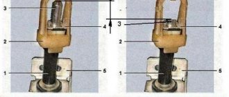
The KI-11140 device includes: a housing with a replaceable flange for installing the device into the nozzle socket; a dial indicator, the leg of which is connected to a rod passing through a guide in the device body; pneumatic receiver for connecting the tip of the compressor-vacuum installation.
To measure the clearances of the crank group with the piston position at TDC and the crankshaft locked, install and secure the device in the injector hole of the cylinder being tested. A compressor-vacuum unit is connected to the device and pressure is created in the space above the piston, the rod is inserted until it comes into contact with the piston bottom and the indicator is set to the zero mark. Then a vacuum is slowly created in the space above the piston and the gap values are measured using an indicator when the piston moves twice. The movement from the zero mark to the first stop corresponds to the clearance in the joints of the upper head of the connecting rod, and the movement from the first stop to the second corresponds to the clearance in the connecting rod bearings. The total movement corresponds to the total clearance in the connecting rod bearings and in the upper end of the connecting rod. The permissible value of the total clearance for different engines is 0.6...0.75 mm, the maximum clearance values for the upper head of the connecting rod are 0.4...0.45 mm, and for connecting rod bearings - 0.45...0.55 mm. The size of the measured gaps is used to judge the condition of each crank group and the entire engine. If the permissible clearance values in at least one cylinder are exceeded, engine repair is necessary. Based on the measurement results, the remaining engine life is predicted (the forecast is made taking into account the maximum value of the measured gaps).
The compressor-vacuum unit is also used in diagnosing the crank group based on vibration-acoustic parameters.
Read more >>Section contents
Maintenance of crank crankshaft and timing gears
Main works:
- checking the stability of the condition and tightening the fastenings (fastening work) of the engine mount to the frame, the cylinder head and the oil pan to the block, the flanges of the intake and exhaust pipelines and other connections;
- checking the technical condition or operability (control work) of the crank and distribution mechanisms;
- adjustment work and lubrication.
Fastening works
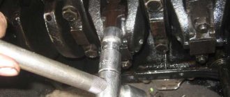
To prevent the passage of gases and coolant through the cylinder head gasket, it is necessary to periodically check the head fastening with a torque wrench with a certain force and sequence. The tightening torque and sequence of tightening the nuts are set by automobile factories.
The cast iron head is attached when the engine is hot, and the aluminum alloy head is attached when it is cold.
The need to tighten the fastening of aluminum alloy heads in a cold state is explained by the unequal coefficient of linear expansion of the material of bolts and studs (steel) and the material of the head (aluminum alloy). Therefore, tightening the nuts on a hot engine does not ensure the required tight fit of the cylinder head to the block after it cools down.
The tightening of the crankcase sump mounting bolts is also checked in accordance with the sequence to avoid crankcase deformation and leaks. alternately tightening diametrically opposed bolts.
Monitoring the condition of the crankshaft and timing gear
The technical condition of these mechanisms can be determined:
- by oil consumption (waste) during operation and pressure drop in the lubrication system;
- by changes in pressure (compression) in the engine cylinders at the end of the compression stroke;
- by vacuum in the intake manifold;
- by the amount of gases breaking into the engine crankcase;
- leakage of gases (air) from the cylinders;
- presence of knocks in the engine.
Oil loss in a low-wear engine is insignificant and can be 0.1-0.25 l/100 km. With significant general engine wear, waste can reach 1 l/100 km or more, which is usually accompanied by heavy smoking.
The pressure in the engine oil system must be within the limits established for the given engine type and the type of oil used. A decrease in oil pressure at low crankshaft speeds of a warm engine indicates the presence of unacceptable wear on the engine bearings or a malfunction in the lubrication system.
A drop in oil pressure on the pressure gauge to 0 indicates a malfunction of the pressure gauge or pressure relief valve.
Increased pressure in the lubrication system can occur as a result of high viscosity or clogging of the oil line.
Compression serves as an indicator of the tightness of the engine cylinders and characterizes the condition of the cylinders, pistons and valves. The tightness of the cylinders can be determined with a compression gauge.
Compression is checked after preheating the engine to 70-80 ºС with the spark plugs turned out. Having installed the rubber tip of the compression gauge in the hole of the spark plug, turn the engine crankshaft 10-12 revolutions with the starter and record the readings of the compression gauge. The check is repeated 2-3 times for each cylinder.
If the compression value is 30-40% below normal, this indicates the presence of malfunctions (broken or burned piston rings, valve leaks or gasket damage).
The vacuum in the engine intake pipe is measured with a vacuum gauge. The magnitude of the vacuum in engines operating in steady state can vary not only from the wear of the cylinder-piston group, but also from the condition of the gas distribution parts, ignition installation and carburetor adjustment.
Thus, this control method is general and does not allow identifying one or another malfunction based on one indicator.
The amount of gases breaking into the engine crankcase changes as a result of the leakage of the cylinder-piston-piston ring interfaces, which increases as these parts wear out. The amount of gases escaping is measured at full engine load.
Other articles on engine systems
- Crank mechanism (CSM)
- Gas distribution mechanism (GRM)
- Hydraulic valve tappet
- Engine lubrication system
- Engine crankcase ventilation
- Engine cooling system
- Cooling System Maintenance
- Starter - purpose, device, operation
- Electronic engine control
- Sensors for monitoring engine operating parameters
Engine frame
The fixed parts of the crank mechanism connected to each other are the core of the engine, which absorbs all the main power and thermal loads, both internal (related to the operation of the engine) and external (due to the transmission and chassis). The force loads transmitted to the engine frame from the vehicle's supporting system (frame, body, housing) and back significantly depend on the method of engine mounting. Usually it is attached at three or four points so that loads caused by distortions of the supporting system that occur when the machine moves over uneven surfaces are not taken into account. The engine mounting must exclude the possibility of its displacement in the horizontal plane under the influence of longitudinal and transverse forces (during acceleration, braking, turning, etc.). To reduce vibration transmitted to the supporting system of the vehicle from a running engine, rubber cushions of various designs are installed between the engine and the sub-engine frame at the mounting points.
The piston group of the crank mechanism is formed by a piston assembly with a set of compression and oil rings, a piston pin and its fastening parts. Its purpose is to perceive gas pressure during the power stroke and transmit force to the crankshaft through the connecting rod, carry out other auxiliary strokes, and also seal the above-piston cavity of the cylinder to prevent gases from breaking through into the crankcase and the penetration of engine oil into it.
Breakdowns and problems of the crank mechanism
Almost all parts of the crankshaft drive are friction pairs, which is clearly confirmed by the diagram of the kinematics of the vehicle drive. If the diagnosis of this internal combustion drive mechanism reveals malfunctions, a major overhaul of the engine is necessary, since it is completely disassembled.
Technical features of crankshaft drive malfunctions include wear of friction parts. The main breakdowns are:
- stuck rings on the pistons - due to high metal production, play appears, misalignment occurs and the piston becomes jammed inside the cylinder;
- wear of the piston pins - instead of a fixed size between the crankshaft/piston, the distance becomes floating, the torque characteristics change;
- development of the piston group - the cylinder mirror or piston surface is ground off, the characteristics of the internal combustion engine change;
- Bearing wear – the connecting rod or main bearings are worn down, causing shock loads on the shaft.
The main causes of malfunctions are prolonged loads, lack of maintenance, poor quality of lubrication or exhaustion of the drive life.
Position of piston rings
The specified malfunctions of the crank mechanism are diagnosed based on the following symptoms:
- interruptions in engine operation;
- a constant decrease in the lubricant level in the crankcase;
- exhaust gases take on a blue tint.
The breakdown cannot be repaired at home, as it requires a highly qualified technician and complete disassembly of the engine.
Wear of pistons and pins
These specific malfunctions of the crank mechanism are identified by the following signs:
- fingers - regardless of the operating mode of the engine, a loud knocking sound is heard in the upper part of the cylinder block, which disappears when the spark plug is unscrewed, and increases as the shaft speed increases;
- pistons - blue exhaust, knocking sound similar to the previous case, but only at idle, after warming up it usually disappears.
After diagnosing this malfunction, a major overhaul of the internal combustion engine is required.
Wear of connecting rod and main bearings
Repair of the crank mechanism will inevitably be required when the bearing life is exhausted, as evidenced by the following factors:
- connecting rod bearing - a warning light indicates insufficient lubricant pressure, a dull, floating knocking sound comes from the middle part of the cylinder block;
- main bearing - the warning light lights up, indicating low oil pressure, a dull knock occurs in the lower part of the cylinder block.
By analogy with the previous options, it will not be possible to do without major repairs.
In the receiver
In this case, during operation of the compressor, air is pumped out of the rarefied air receiver and out of the compressor into the atmosphere. To create pressure in the compressed air receiver, the discharge cavity of the compressor is connected to it, and the suction cavity is disconnected from the rarefied air receiver and connected to the atmosphere. In this case, air from the atmosphere is pumped through the compressor into the compressed air receiver.
A vacuum of 0.06 ... 0.07 MPa is created in the rarefied air receiver, and a pressure of 0.2 ... 0.25 MPa is created in the compressed air receiver.
To connect the installation, remove the injector from the engine cylinder being tested, set the piston to TDC and, by engaging the gear, fix the position of the piston. After this, the tip of the compressor-vacuum unit is inserted into the injector hole and secured to the engine. During installation of the tip, access to air from the receivers is blocked. The stethoscope is installed in the zone of best listening to knocks at the interface between the piston and piston pin - the upper head of the connecting rod and then, using an air distributor, it is alternately connected above the piston cavity either to a rarefied air receiver or to a compressed air receiver. The vacuum and compression that occurs in the combustion chamber moves the piston by the amount of the gaps in the joints, which leads to knocking noises both in the upper head of the connecting rod and in the connecting rod bearings. To detect knocking noises in connecting rod bearings during operation of a compressor-vacuum installation, the tip of a stethoscope is applied to the end of the crankshaft.
After checking one cylinder in this way
The diagnostic results in this case largely depend on the operator’s experience, therefore, to make a final decision on the state of the joints being checked, the total gap in the upper head of the connecting rod and the connecting rod bearing is measured using the K GT-11140 indicator device or the KI-7329 device.
Determining the condition of the crankshaft by the gaps in its mates
A conclusion about the condition of the crankshaft can be made by the size of the gaps in its mates. The total clearance in the upper head of the connecting rod and the connecting rod bearing is measured with a KI-11140 GOSNITI device.
To measure gaps you need:
- set the piston of the cylinder being tested to TDC on the compression stroke and lock the crankshaft
- fix the device in the cylinder head instead of the injector by loosening the locking screw and lifting the guide with the indicator and the rod up
- lower the guide until the rod stops at the piston bottom (by tension) and secure it with a screw
- connect the distribution pipeline of the compressor-vacuum unit to the fitting of the pneumatic receiver
- turn on the installation and bring the pressure and vacuum in its receivers to 0.06–0.1 MPa and 0.06–0.07 MPa, respectively
- perform two or three cycles of supplying pressure and vacuum to the above-piston space by switching the distribution valve until stable indicator readings are obtained
- connect the compressed air receiver to the space above the piston with a tap and set the indicator to zero
- smoothly connect the rarefied air receiver to the space above the piston and use the indicator to first record the gap in the connection between the piston pin and the upper head of the connecting rod, then the total gap in the upper head of the connecting rod and the connecting rod bearing
The gaps in the crankshaft are measured 3 times and the average value is taken.
If the clearances of at least one connecting rod exceed the permissible values, the engine must be repaired.
Preliminary assessment of the condition of the crankshaft coupling based on oil pressure and knocks
A preliminary assessment of the condition of the crankshaft couplings can be obtained from the oil pressure in the main line and the nature of knocking in certain areas of the engine.
Oil pressure is checked using a KI-5472 GOSNITI device, which consists of a pressure gauge, a connecting hose with a nipple and a union nut, a damper to smooth out oil pulsations when measuring pressure, and replaceable fittings. To measure the pressure in the main line of a diesel engine, the device is connected to the oil filter housing by disconnecting the standard pressure gauge tube.
| Purpose, design and principle of operation of the KShM |
| How to care for CVS? |
| KShM malfunctions |
| KShM repair |
| Forces acting on the crankshaft parts |
To check the pressure, do the following:
- connect to the oil filter housing KI-5472
- start and warm up the engine to normal thermal condition
- record the oil pressure in the line at the nominal and minimum stable crankshaft speed at idle
Knocks in the CV joints are listened to when the engine is not running using an electronic autostethoscope TU 14 MO.082.017, alternately creating a vacuum and pressure in the space above the piston using a compressor-vacuum unit KI-4912 GOSNITI or KI-13907 GOSNITI. Listen for knocks at the interfaces of the piston boss - piston pin, piston pin - bushing of the upper head of the connecting rod, crankshaft journal - connecting rod mechanism.
If the oil pressure is below the permissible values, if there are knocks in the crankshaft joints, check the gaps in the indicated joints. If the oil pressure is low and there are no knocks, check the adjustment of the lubrication system drain valve. If this does not give positive results, check the oil supply by the pump and the condition of the pressure reducing valve of the lubrication system on the stand.
Operating principle and purpose
Introduction Maintenance and repair of the brake system of the VAZ-2109 car
Unlike an electric motor, the operating principle of a crankshaft in internal combustion engines is much more complicated:
- the pistons are alternately pushed out of the cylinders when the fuel mixture is ignited;
- connecting rod parts of complex configuration are hinged inside them;
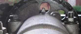
- the crankshaft has a U-shaped reciprocal seating surface for the lower head of the connecting rod, which ensures displacement from the axis of rotation of the shaft;
- due to the fixed distance between the piston and the crankshaft, the connecting rod describes an amplitude in the form of a figure eight, due to which the translational movement from the cylinders is converted into torque on the shaft.
Self-check of a car engine with an injection system
In most modern power units, fuel enters the fuel system through special elements that spray it, called injectors. This feed is considered more progressive than in carburetor cars. However, errors in work sometimes arise in it. Since its further combustion depends on the quality of fuel atomization, it is extremely important to prevent failures in the mechanisms that supply fuel.
Personal diagnostics of injection engines is carried out to identify faults in the injection system. Timely elimination of problems discovered during the study can prevent more significant troubles that threaten unplanned financial losses caused by the need for major repairs.
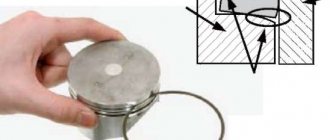
Piston
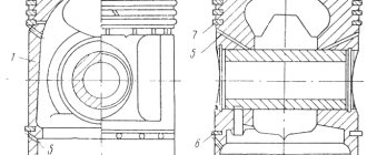
The piston is a metal glass of complex shape, installed in a cylinder with the bottom up. It consists of two main parts. The upper thickened part is called the head, and the lower guide part is called the skirt. The piston head contains a bottom 4 (Fig. a) and walls 2. Grooves 5 for compression rings are machined in the walls. The lower grooves have drainage holes 6 to drain oil. To increase the strength and rigidity of the head, its walls are equipped with massive ribs 3 that connect the walls and bottom with bosses in which the piston pin is installed. Sometimes the inner surface of the bottom is also ribbed.
The skirt has thinner walls than the head. In its middle part there are bosses with holes.
The piston heads can be flat (see a), convex, concave and shaped (Fig. b-h). Their shape depends on the type of engine and combustion chamber, the adopted mixture formation method and the piston manufacturing technology. The simplest and most technologically advanced is the flat form. Diesel engines use pistons with concave and shaped bottoms (see Fig. e-h).
When the engine is running, the pistons heat up more than cylinders cooled by liquid or air, so the expansion of the pistons (especially aluminum ones) is greater. Despite the presence of a gap between the cylinder and the piston, jamming of the latter may occur. To prevent jamming, the skirt is given an oval shape (the major axis of the oval is perpendicular to the piston pin axis), the diameter of the skirt is increased compared to the diameter of the head, the skirt is cut (most often a T- or U-shaped cut is made), and compensation inserts are poured into the piston to limit thermal expansion skirts in the plane of swing of the connecting rod, or forcefully cool the internal surfaces of the piston with jets of engine oil under pressure.
A piston subjected to significant force and thermal loads must have high strength, thermal conductivity and wear resistance. In order to reduce inertial forces and moments, it must have a low mass. This is taken into account when choosing the design and material for the piston. Most often the material is aluminum alloy or cast iron. Sometimes steel and magnesium alloys are used. Promising materials for pistons or their individual parts are ceramics and sintered materials that have sufficient strength, high wear resistance, low thermal conductivity, low density and a small coefficient of thermal expansion.
Purpose, design, operating principle of the crank mechanism
Purpose and design of the crank mechanism
The connecting rod mechanism converts the reciprocating linear motion of the pistons, which feel the pressure of the gases, into the rotational movement of the crankshaft.
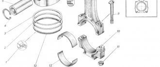
The crank mechanism consists of the following parts: Pistons with rings and journals, connecting rods, crankshaft and flywheel. The pistons are located in cylinders, which are installed in a block housing, closed at the top by the cylinder head.
Piston assembly and connecting rod. The piston with sealing rings, piston pins and clamping parts form the piston group. The piston and piston ring provide a seal to the variable displacement in which the engine operates, absorb gas pressure and transmit the resulting force to the crankshaft through the piston pin and connecting rod. The piston also serves to fill the cylinder with fuel or air, compress and remove exhaust gases from the cylinder. In two-stroke engines, the piston also opens the intake, exhaust and bypass ports. The piston is exposed to high pressure, high temperatures and rapidly changing speeds.
The piston consists of an upper sealing part (head) and a lower guide part (skirt). For better heat dissipation and increased strength, the crown has stiffening ribs on the inside of the piston. From the outside, the crown can be flat, concave, convex or shaped.
The side surface of the piston has a complex elliptical cone shape and its diameter is smaller than the diameter of the cylinder, while the diameter of the piston head is smaller than the diameter of the skirt, and the main axis of the ellipse is perpendicular to the axis of the piston ring. All this allows the piston to create a gap between the cylinder walls and the piston during heating and expansion, allowing the piston to expand and move freely within the cylinder.
The skirt provides directional movement of the piston in the cylinder and transmits lateral forces to the cylinder walls. The top of the skirt tube has cam holes for the piston pin connecting the piston to the connecting rod. The pin axis intersects the piston axis, but is sometimes offset from the piston axis. This reduces the load on the piston when it reaches top dead center. To improve piston entry into the cylinders, reduce wear and protect against seizing, the piston skirt is coated with a thin layer of tin. The piston itself is cast from a special aluminum alloy.
Piston rings are divided into compression and scraper rings. Their purpose is to prevent the passage of gases between the cylinder walls and the piston, as well as the penetration of oil from the crankcase into the combustion chamber, where it burns and forms soot. The rings are involved in removing heat from the piston to the cylinder. When loose, the outer diameter of the ring is larger than the diameter of the cylinder so that it fits tightly against the cylinder wall when installed.
To install piston rings into the grooves, cuts are made with a gap of 0.2 - 0.5 mm. Slotted piston rings, known as lock rings, are predominantly straight, sometimes sloped or stepped. As a result of use and wear, the piston rings lose their elasticity, which affects the tightness of the cylinder. Piston rings are made from either machined alloy iron castings or steel. The height of the rings is 0.03-0.08 mm lower than the height of the groove in the piston.
The material of the piston rings must have good elasticity and sufficient strength at high temperatures, with high wear resistance, which, however, should not be higher than that of the cylinder bore. To reduce wear on the ring and cylinder, the contact surface of one or two upper compression piston rings is coated with a layer of chromium up to 0.16-0.20 mm thick with a porous surface that retains lubricant. To improve running-in, the working surfaces of the lower rings are often coated with a layer of tin or other easily abraded material.
The piston pin connects the piston and connecting rod and is made of high-quality, wear-resistant steel. The inner surface of the pin is cylindrical or conical-cylindrical.
The ends of the pin are placed in the holes in the piston crown, and the center passes through the end hole of the rod. When the pins rotate freely in both the hubs and the rod, they are called floating pins. This connection is the most common because when the piston and connecting rod move, the entire surface of the floating pin is in working order, reducing wear and the likelihood of binding.
On some engines, the pin may be fixed in the head of the connecting rod and have a length less than the diameter of the piston. To limit axial movement of the pin and prevent damage to the cylinder walls, the pin is secured by snap rings installed in the grooves of the bushings, end caps installed in the hubs, and a snap ring located in the grooves of the pin and the top of the connecting rod.
The piston pin is lubricated by holes in the rod or grooves in the connecting rod head and by oil passages in the piston pin bobbins.
The connecting rod is used to connect the piston to the crankshaft. When the engine is running, the connecting rod transmits power from the piston to the crankshaft during its power stroke, and during the remaining strokes it moves the piston around the cylinder. The rod converts the reciprocating motion of the piston into rotational motion of the crankshaft.
Connecting rods consist of an upper and lower head and a connecting rod: the upper head is inseparable and serves to hold the piston pin, which turns the piston on the connecting rod. To reduce friction and wear, one or two bronze bushings are pressed into it; the lower head of many engines is made straight (90°) or inclined (30 - 60°) relative to the axis of the connecting rod of the connecting rod combined. The parting line can be smooth or have splines. The diagonal pitch facilitates the passage of the piston and connecting rod through the cylinder - connecting rod to the crankshaft - crank.
The removable part of the lower end of the connecting rod is the cover. It is attached to the stud with two bolts that are screwed or threaded into the body of the stud and then tightened.
In the lower head of the connecting rod there are thin-walled steel shells (top and bottom) with a thin layer of friction alloy 0.1 - 0.9 mm. The bearing bushes act as plain bearings and fit snugly against the stem and cap, with their lugs engaging in corresponding recesses in the stem and cap.
The connecting rods are usually I-beams with a streamlined, smooth transition to the lower heads. Some connecting rods have a compression passage through the rod to the piston pin.
When the engine is running, gas pressure and inertia forces act on the connecting rod, compressing, stretching and bending it in the longitudinal and transverse directions. Therefore, its shape, design and material must ensure strength, rigidity and lightness. Connecting rods are made from high-quality carbon and alloy steel by hot forging followed by mechanical and heat treatment.
To ensure good engine balance, the weight difference between individual connecting rods and connecting rod and piston sets should be kept to a minimum. To install the pistons and connecting rods so that they can be installed correctly in the engine, the cylinder number of the connecting rod and its cap, as well as other markings, are stamped on the lower end of the connecting rod.
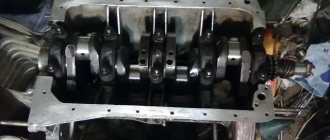
Crankshaft and flywheel. The crankshaft consists of a main and connecting journals connected by jaws, a flange for installing the flywheel and a guide.
The journals are used to support the crankshaft in bearings located in the crankcase. The connecting rods connect the shaft to the lower connecting rod heads. The journals and main journals are connected by crank journals. To remove inertial forces from the main bearings of the moving parts of the connecting rods, balancing weights are installed on the crankshaft shoes. Balance weights can be built into the clamping jaws or can be manufactured as separate, securely mounted components. The neck with its cheeks represents a crankshaft or crankshaft.
To prevent crankshaft failure in the transition zones from the cheeks to the crank journal and the crank pin, perform rounding - filleting. There are holes in the connecting rod journals and crankshaft journals that provide pressurized oil to the connecting rod bearings.
At the front end of the crankshaft there is a camshaft drive gear, a timing belt pulley, an oil slinger, an oil seal and a crankshaft ratchet. The flywheel is bolted to the crankshaft. The joint shaft has an oil thread and an oil vortex, at the end of which there is a spline for the bearing of the front part of the coupling.
The shaft nose and shaft are sealed with self-sealing rubber bushings. The crankshaft rotates in main bearings, which have inserts made of steel-aluminum strip.
Crankshafts are made of carbon and alloy steel by forging or casting followed by mechanical and heat treatment. To increase the wear resistance of the crankshaft journals and connecting rods, they are surface hardened, and then ground and polished.
The shape of the crankshaft depends on the number and arrangement of cylinders, the duty cycle and engine operation. It must ensure uniform stroke rotation in the cylinders above the crankshaft angle, the intended cylinder firing sequence and engine balance.
The number of crank pins on the crankshaft of an engine with a single-row cylinder arrangement is equal to the number of cylinders. For V-cylinder engines, the number of connecting rods is equal to half the number of cylinders: these engines have two connecting rod heads side by side on each connecting rod. V-twin engines typically have one more crankshaft journal than crankshaft connecting journals.
The main bearing shells are installed into the crankcase frame and main bearing cap and are secured in the same way as the connecting rod bearings.
The flywheel ensures smooth rotation of the crankshaft, starting and cranking of the engine. When the engine flywheel starts, the energy after the stroke in one of the cylinders ensures rotation due to the inertia of the crankshaft, and in the other cylinders the conditions for the flow of working strokes, as a result of which the engine begins to work.
The flywheel is cast like a cast iron disc. To increase the moment of inertia of the flywheel, most of its metal has an edge, that is, at the maximum distance from the axis of rotation of the flywheel. The flywheel rim presses onto a steel ring gear that starts the engine, starter gears, and makes markings to determine the position of the piston in the first cylinder and adjust ignition timing or fuel supply.
The flywheel is balanced along with the crankshaft. This is done to prevent vibration and runout caused by centrifugal forces, as well as to prevent increased wear on the engine main bearings. The clutch is mounted on the rear side of the flywheel.
During engine operation, the crankshaft is exposed to axial forces from the timing gears, clutch and shaft heat. To limit the axial displacement of the crankshaft, one of the main bearings (rear, front or center) extends. This is achieved by equipping the bearing shells with flares, thrust washers or retaining rings.
Cylinder
Cylinders are the guiding elements of the crank mechanism. Pistons move inside them. The length of the cylinder generatrix is determined by the stroke of the piston and its dimensions. Cylinders operate under conditions of sharply changing pressure in the above-piston cavity. Their walls come into contact with flames and hot gases with temperatures up to 1500... 2500 °C.
Cylinders must be strong, rigid, heat and wear resistant with limited lubrication. In addition, the cylinder material must have good casting properties and be easy to machine. Typically, cylinders are made from special alloy cast iron, but aluminum alloys and steel can also be used. The inner working surface of the cylinder, called its mirror, is carefully processed and plated with chrome to reduce friction, increase wear resistance and durability.
In liquid-cooled engines, the cylinders may be cast together with the cylinder block or as separate liners installed in the block bores. Between the outer walls of the cylinders and the block there are cavities called a cooling jacket. The latter is filled with liquid that cools the engine. If the cylinder liner is in direct contact with the coolant with its outer surface, then it is called wet. Otherwise it is called dry. The use of replaceable wet liners makes engine repair easier. When installed in a block, wet liners are reliably sealed.
Air-cooled engine cylinders are cast individually. To improve heat dissipation, their outer surfaces are equipped with annular fins. On most air-cooled engines, the cylinders and their heads are secured with common bolts or studs to the top of the crankcase.
In a V-shaped engine, the cylinders of one row may be slightly offset relative to the cylinders of the other row. This is due to the fact that two connecting rods are attached to each crank of the crankshaft, one of which is intended for the piston of the right half of the block, and the other for the piston of the left half of the block.
Operating principle of the crank mechanism
In the case of crank drives, it should be noted that both forward and reverse movement are possible.
Forward Movement: The piston moves downward under gas pressure while it moves up the crankshaft. The forward movement of the piston is converted into rotational movement of the crankshaft through the connecting rod and piston-connecting rod coupling.
The crankshaft consists of:
*Cervix
* crank pin
* counter magazines
Reverse diagram: under the influence of an applied external torque, the crankshaft rotates, which is converted into translational motion of the piston by the kinematic chain “crankshaft - connecting rod - piston”.
In this chapter, we studied the structure and working of the crank mechanism. We have identified the crank mechanism and technical components.